Note: Descriptions are shown in the official language in which they were submitted.
LOCKING ASSEMBLY FOR A DISPENSER AND
DISPENSER
TECHNICAL FIELD
The present disclosure generally relates to locking assemblies to lock
together two
elements. More particularly, the present disclosure relates to a locking
assembly
configured to lock together a base part and a cover of a dispenser, the base
part and
the cover defining together a dispensing chamber, to contain, for instance, a
web
material roll. The present disclosure further relates to a dispenser including
the
locking assembly.
BACKGROUND
Several types of web material roll dispensers exist to gradually provide a
user of the
web material roll dispenser with different types of web material. The most
common
types of dispensers dispense paper items such as paper towels and toilet
paper.
In the dispenser field, locking assemblies are used to lock a base part and a
cover
together in a closed configuration. Several types of locking assemblies exist
which
include a key enabling the configuration of the locking assembly into an
unlocked
configuration, so as to provide access to a dispensing chamber of the
dispenser, for
instance to fill it with web material to be dispensed. However, the key might
be lost or
damaged, such an event jeopardizing the possibility of configuring the
dispenser in
the open configuration, and thus jeopardizing the use of the dispenser. Some
other
known locking assemblies comprise a pushbutton onto which pressure must be
applied to configure the locking assembly into the unlocked configuration.
However,
it is not fully satisfactory since these dispensers are often used in public
area, such
as washrooms, and thus an ill-intentioned person could unlock the locking
assembly,
for instance to remove the web material out of the dispensing chamber.
In view of the above, there is a need for an improved dispenser comprising a
locking
assembly which would be able to overcome or at least minimize some of the
above-
discussed prior art concerns.
File No. 11358-926 - 1 -
CA 3041498 2019-04-26
BRIEF SUMMARY
It is therefore an aim of the present invention to address the above-mentioned
issues.
According to a general aspect, there is provided a locking assembly mountable
to a
.. dispenser having a base part and a cover movable relative to each other
between a
closed configuration and an open configuration, the locking assembly being
configured to lock the base part and the cover in the closed configuration
when
mounted to the dispenser, the locking assembly comprising an unlocking
component
mountable to one of the base part and the cover and comprising: an unlocking
body
translatable to configure the locking assembly into an unlocked configuration;
and a
pushbutton at least partially contained in the unlocking body. The locking
assembly
is selectively configurable into a key-opening configuration wherein the
pushbutton is
prevented from translation and in a pushbutton-opening configuration wherein
pressure on the pushbutton engages the unlocking body into translation to
configure
the locking assembly into the unlocked configuration.
According to another general aspect, there is provided a web material
dispenser
comprising: a housing defining a dispensing chamber and having a base part and
a
cover movable relative to each other between a closed configuration in which
the
dispensing chamber is at least partially closed, and an open configuration for
providing access to the dispensing chamber; and a locking assembly according
to
the present disclosure to lock the base part and the cover in the closed
configuration,
the unlocking component being mounted to one of the base part and the cover.
According to another general aspect, there is provided a dispenser comprising:
a
housing defining a dispensing chamber and having a base part and a cover
movable
relative to each other between a closed configuration in which the dispensing
chamber is at least partially closed, and an open configuration for providing
access
to the dispensing chamber; and a locking assembly mounted to one of the base
part
and the cover to lock the base part and the cover in the closed configuration,
the
locking assembly comprising an unlocking component including: an unlocking
body
.. translatable to configure the locking assembly into an unlocked
configuration, and a
pushbutton at least partially contained in the unlocking body. The locking
assembly
File No. 11358-926 - 2 -
CA 3041498 2019-04-26
is selectively configurable in a key-opening configuration wherein the
pushbutton is
prevented from translation and in a pushbutton-opening configuration wherein
pressure on the pushbutton engages the unlocking body into translation to
configure
the locking assembly into the unlocked configuration.
According to another general aspect, there is provided a dispenser comprising
a
housing. The housing defines a dispensing chamber and has a base part and a
cover movable between a closed configuration in which the dispensing chamber
is at
least partially closed, and an open configuration for providing access to the
dispensing chamber. The dispenser further comprises a locking assembly to lock
the
base part and the cover in the closed configuration. The locking assembly
comprises
an unlocking component including an unlocking body translatable to configure
the
locking assembly into an unlocked configuration, and a pushbutton at least
partially
contained in the unlocking body. The locking assembly is selectively
configurable in
a key-opening configuration wherein the pushbutton is prevented from
translation
and in a pushbutton-opening configuration wherein pressure on the pushbutton
engages the unlocking body into translation to configure the locking assembly
into
the unlocked configuration.
According to another aspect, there is provided a dispenser comprising a
housing.
The housing defines a dispensing chamber and has a base part and a cover
movable between a closed configuration in which the dispensing chamber is at
least
partially closed, and an open configuration for providing access to the
dispensing
chamber. The dispenser further comprises a locking assembly to lock the base
part
and the cover together in the closed configuration. The locking assembly
comprises
a catch-engaging portion mounted to one of the base part and the cover, a lock
catch mounted to the other one of the base part and the cover pivotable about
a
pivoting axis and engageable with the catch-engaging portion to maintain the
base
part and the cover in the closed configuration, and an unlocking component.
The
unlocking component comprises an unlocking body translatable along an
unlocking
axis extending substantially parallel to the pivoting axis and configured to
contact the
lock catch along the unlocking axis to pivot same into a disengaged
configuration.
The unlocking component further comprises a pushbutton at least partially
contained
in the unlocking body. The locking assembly is selectively configurable in a
key-
File No. 11358-926 - 3 -
CA 3041498 2019-04-26
opening configuration wherein the pushbutton is prevented from translation
along the
unlocking axis and in a pushbutton-opening configuration wherein pressure on
the
pushbutton engages the unlocking body into translation to configure the
locking
assembly into the unlocked configuration.
In an embodiment, the locking assembly further comprises: a catch-engaging
portion
mountable to the other one of the base part and the cover; and a lock catch
mountable to the one of the base part and the cover, the lock catch being
configurable between an engaged configuration wherein the lock catch is
engaged
with the catch-engaging portion to maintain the base part and the cover in the
closed
configuration when the locking assembly is mounted to the dispenser, and a
disengaged configuration wherein the lock catch is disengaged from the catch-
engaging portion for the base part and the cover to be configurable in the
open
configuration when the locking assembly is mounted to the dispenser. The lock
catch
can be configured into the disengaged configuration when the locking assembly
is
configured into the unlocked configuration. The lock catch can be pivotably
mountable to the one of the base part and the cover about a pivoting axis. The
unlocking body can be translatable along an unlocking axis extending
substantially
parallel to the pivoting axis. The unlocking body can comprise a peripheral
wall
having a tapered shape and engaging with the lock catch when the unlocking
body is
translated along the unlocking axis. The unlocking body can comprise an
actuation
end and an opposed unlocking end cooperating with the lock catch when the
unlocking body is translated along the unlocking axis, the peripheral wall of
the
unlocking body being tapered towards the unlocking end. A through opening can
be
formed in the unlocking body, the pushbutton being at least partially slidably
received
in the through opening. The pushbutton can comprise a head protruding
externally
from the actuation end of the unlocking body, the actuation end of the
unlocking
body having an outer surface including a central portion covered by the head
of the
pushbutton and an exposed portion, surrounding the central portion. The
exposed
portion of the actuation end of the unlocking body can be substantially
annular in
shape.
File No. 11358-926 - 4 -
CA 3041498 2019-04-26
In an embodiment, the locking assembly further comprises: a biasing member
operatively engaged with the lock catch and exerting a biasing force thereto
to bias
the lock catch into the engaged configuration.
In an embodiment, the lock catch comprises an arm having a first end pivotally
mountable to the one of the base part and the cover, and a second end
comprising a
hook engageable with the catch-engaging portion.
In an embodiment, the lock catch comprises first and second catch portions
defining
a gap therebetween, the unlocking body being translatable into the gap. The
first
and second catch portions can be pivotably mountable to the one of the base
part
and the cover about substantially parallel first and second pivoting axes.
In an embodiment, the locking assembly further comprises: a locking casing
mountable to the one of the base part and the cover and defining an interior
volume
containing at least partially the unlocking component.
In an embodiment, the locking assembly further comprises: a function switch
movable between a pushbutton-blocking configuration in which the function
switch
prevents the pushbutton from being translated, and a pushbutton displacement
configuration in which the pushbutton is translatable. The function switch can
comprise a pushbutton abutment, the pushbutton abutting against the pushbutton
abutment when the function switch is configured in the pushbutton-blocking
configuration. The unlocking body can comprise an actuation end and an opposed
unlocking end, wherein the pushbutton abutment circumvents the unlocking end
of
the unlocking body, when the function switch is configured in the pushbutton-
blocking configuration. The unlocking body can be translatable along an
unlocking
axis, wherein the function switch is slidably mountable to the one of the base
part
and the cover along a first direction substantially perpendicular to the
unlocking axis.
In an embodiment, the locking assembly further comprises: a key having a
distal end
with a peripheral wall defining a recess to receive a portion of the
pushbutton when
the peripheral wall is at least partially inserted into the peripheral groove.
In an
embodiment, the distal end of the peripheral wall of the key contacts the
exposed
File No. 11358-926 - 5 -
CA 3041498 2019-04-26
portion of the outer surface of the unlocking body when engaged in the
peripheral
groove.
In an embodiment, the function switch is accessible only when the cover and
the
base part are in the open configuration.
BRIEF DESCRIPTION OF THE DRAWINGS
Fig. 1 is a perspective view of an upper portion of a dispenser including a
cover
hingedly mounted to a base part according to the present disclosure, wherein
the
base part and the cover are configured in a partially open configuration;
Fig. 2 is a top perspective view, partially exploded, of an upper portion of
the cover of
the dispenser of Fig. 1;
Fig. 3 is a top perspective view of a first embodiment of a locking assembly
according to the present disclosure;
Figs. 4A and 4B are respectively a perspective view, sectioned, and a cross-
section
view of the locking assembly of Fig. 3 configured in a key-opening
configuration,
without pressure being applied on an unlocking component of the locking
assembly;
Figs. 5A and 5B are respectively a perspective view, sectioned, and a cross-
section
view of the locking assembly of Fig. 3 configured in the key-opening
configuration,
wherein pressure is applied on an unlocking body of the unlocking component to
configure the locking assembly into an unlocked configuration;
Figs. 6A and 6B are respectively a perspective view, sectioned, and a cross-
section
view of the locking assembly of Fig. 3 configured in a pushbutton-opening
configuration, without pressure being applied on the unlocking component;
Figs. 7A and 7B are respectively a perspective view, sectioned, and a cross-
section
view of the locking assembly of Fig. 3 configured in the pushbutton-opening
configuration, wherein pressure is applied on the unlocking component to
configure
the locking assembly into the unlocked configuration;
File No. 11358-926 - 6 -
CA 3041498 2019-04-26
Figs. 8 and 9 are top and bottom perspective views, exploded, of the locking
assembly of Fig. 3;
Fig. 10 is a top perspective view of a second embodiment of a locking assembly
according to the present disclosure, the shape of the unlocking body differing
from
the one of the first embodiment;
Fig. 11 is a bottom plan view of the locking assembly of Fig. 10;
Fig. 12 is a top perspective view, sectioned, of the locking assembly of Fig.
10;
Fig. 13 is a cross-section view of the locking assembly of Fig. 10, the
locking
assembly being in the key-opening configuration;
Fig. 14 is a top perspective view of the locking assembly of Fig. 10, a
locking
assembly cover of the locking assembly being removed;
Figs. 15 and 16 are top and bottom perspective views, exploded, of the locking
assembly of Fig. 10; and
Figs. 17 and 18 are top perspective views of first and second embodiments of
keys
configured to cooperate with locking assemblies according to the present
disclosure.
DETAILED DESCRIPTION
In the following description, the same numerical references refer to similar
elements.
Furthermore, for the sake of simplicity and clarity, namely so as to not
unduly burden
the figures with several reference numbers, not all figures contain references
to all
the components and features, references to some components and features may be
found in only one figure, and components and features of the present
disclosure
which are illustrated in other figures can be easily inferred therefrom. The
embodiments, geometrical configurations, materials mentioned and/or dimensions
shown in the figures are optional and are given for exemplification purposes
only.
Moreover, it will be appreciated that positional descriptions such as "above",
"below",
"forward", "rearward" "left", "right" and the like should, unless otherwise
indicated, be
taken in the context of the figures and correspond to the position and
orientation of
File No. 11358-926 - 7 -
CA 3041498 2019-04-26
the dispenser and corresponding parts when being secured to a wall, with the
"front"
corresponding to a position closer to the user of the dispenser and the "rear"
corresponding to a position closer to the wall to which the dispenser is
secured.
Positional descriptions should not be considered limiting.
Although various features may be described in the context of a single
embodiment,
the features may also be provided separately or in any suitable combination.
Conversely, although the invention may be described herein in the context of
separate embodiments for clarity, it may also be implemented in a single
embodiment.
Reference in the specification to "some embodiments", "an embodiment", "one
embodiment" or "other embodiments" means that a particular feature, structure,
or
characteristic described in connection with the embodiments is included in at
least
some embodiments, but not necessarily all embodiments.
It is to be understood that the phraseology and terminology employed herein is
not to
be construed as limiting and are for descriptive purpose only.
It is to be understood that the terms "including", "comprising", and
grammatical
variants thereof do not preclude the addition of one or more components,
features,
steps, or integers or groups thereof and that the terms are to be construed as
specifying components, features, steps or integers.
If the specification or claims refer to "an additional" element, this does not
preclude
there being more than one of the additional element. It is to be understood
that,
where the claims or specification refer to "a" or "an" element, such reference
is not
be construed that there is only one of that element.
It is to be understood that where the specification states that a component,
feature,
structure, or characteristic "may", "might", "can" or "could" be included,
that particular
component, feature, structure, or characteristic is not required to be
included.
File No. 11358-926 - 8 -
CA 3041498 2019-04-26
General structure of the dispenser
Referring now to the drawings, and more particularly to Figs. 1 and 2, there
is shown
a dispenser 100 comprising a housing 102 defining a dispensing chamber 104.
The housing 102 comprises a base part 106 and a cover 108. The cover 108 and
the
base part 106 are movable relative to each other. The base part 106 has a rear
portion 107 that is configured to be mounted to a supporting surface, for
instance, a
wall. In the embodiment shown, the cover 108 is pivotally mounted to the base
part
106, in the lower portion thereof. Therefore, the cover 108 and the base part
106 are
movable relative to each other between a closed configuration, in which the
dispensing chamber 104 is at least partially closed, and an open
configuration, as
shown in Fig. 1, in which access is provided to the dispensing chamber 104. It
is
appreciated that the shape and the configuration of the base part 106 and the
cover
108 could vary from the embodiment shown. The cover 108 could for instance and
without being !imitative be pivotable about a substantially vertical axis and
be
pivotally mounted to a lateral portion of the base part 106.
The dispenser 100 further comprises a locking assembly 110, which can be
selectively and alternatively configured in a locked configuration, in which
the cover
108 and the base part 106 are locked together in the closed configuration, and
an
unlocked configuration in which the cover 108 and the base part 106 are free
from
being moved relative to each other (for instance, in which the cover 108 is
free from
being pivoted away from the base part 106) so that the base part 106 and the
cover
108 can be configured in the open configuration.
As will further be described in more details, the lock assembly 110 comprises
a
catch-engaging portion 112 mounted, in the shown embodiment, to the base part
106 of the dispenser 100, and a lock catch 114 mounted, in the shown
embodiment,
to the cover 108. The lock catch 114 is engageable with the catch-engaging
portion
112 to maintain the base part 106 and the cover 108 in the closed
configuration. In
other words, the lock catch 114 is displaceable between an engaged
configuration in
which the lock catch 114 is engaged with the catch-engaging portion 112 to
maintain
the base part 106 and the cover 108 in the closed configuration, and a
disengaged
configuration in which the lock catch 114 is disengaged from the catch-
engaging
File No. 11358-926 - 9 -
CA 3041498 2019-04-26
portion 112 for the base part 106 and the cover 108 to be displaceable
relative to
each other to be configurable into the open configuration. It is appreciated
that, in an
alternative embodiment (not shown), the base part 106 can include the lock
catch
114 while the cover 108 includes the catch-engaging portion 112.
.. As shown in Fig. 2, the cover 108 of the dispenser 100 comprises a locking
casing
109. In the embodiment shown, the locking casing 109is located in the
dispensing
chamber 104 of the housing 102 and protrudes inwardly from an inner surface of
an
upper wall 111 of the cover 108. With the upper wall or a portion of the
locking
assembly 110, the locking (or inner) casing 109 delimits an interior volume
105 that
is dimensioned and shaped to receive at least some components of the locking
assembly 110. In the embodiment shown in which the lock catch 114 is mounted
to
the cover 108, the inner casing 109 is configured (i.e. is dimensioned and
shaped) to
receive at least a portion of the lock catch 114.
Moreover, as shown in Figs. 3 to 16, the locking assembly 110 further
comprises an
unlocking component 120 having an unlocking body 130 displaceable
(translatable in
the embodiment shown) to configure the locking assembly 110 into the unlocked
configuration.
The unlocking component 120 further comprises a pushbutton 140 at least
partially
contained in the unlocking body 130.
The locking assembly 110 is selectively configurable in a key-opening
configuration
wherein the pushbutton 140 is prevented from translation in the interior
volume 105
of the inner casing 109 (or with respect to the housing 102) and wherein
pressure
should be applied directly onto the unlocking body 130 to engage the unlocking
body
130 into translation in the interior volume 105 of the inner casing 109.When
the
locking assembly 110 is configured in the key-opening configuration, a key 180
as
shown in Figs. 17 and 18 is needed to translate the unlocking body 130 in the
inner
casing 109. The locking assembly 110 is further selectively configurable in a
pushbutton-opening configuration wherein pressure applied on the pushbutton
140
engages the unlocking body 130 into translation in the inner casing 109 to
configure
the locking assembly 110 into the unlocked configuration.
File No. 11358-926 - 10 -
CA 3041498 2019-04-26
In other words, the locking assembly 110 is configured so that, when it is
configured
in the key-opening configuration, the key 180 is required to configure the
locking
assembly 110 in the unlocked configuration, whereas when the locking assembly
110 is configured in the pushbutton-opening configuration, no key is required
to
configure the locking assembly 110 into the unlocked configuration. A pressure
applied on the pushbutton 140 of the unlocking component 120 is sufficient for
the
locking assembly 110 to be configured in the unlocked configuration.
In the following description, the terms "inner" and "outer" should be
understood,
unless otherwise stated, with regards to the interior volume 105 of the inner
(or
locking) casing 109 in which at least some of the components of the locking
assembly 110 are arranged or with regards to the dispensing chamber 104 of the
housing 102. In other words, the term "outer" should be understood, unless
otherwise stated, as being relative to a volume outside the interior volume
105 of the
locking casing 109 or as being exposed outwardly of the interior volume of the
locking casing 109 (or with regards to the dispensing chamber 104 of the
housing
102).
First embodiment of the locking assembly
Description of the components
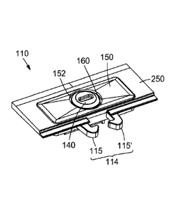
A first embodiment of the locking assembly 110 is shown in Figs. 3 to 9.
In the shown embodiment, the unlocking body 130 has a substantially frusto-
conical
shape having an outer end 132 (or actuation end 132), in the shape of an
exposed
rim, and an opposed inner end 134 (or unlocking end 134). The substantially
frusto-
conical shape of the unlocking body 130 converges towards the unlocking end
134.
In other words, the unlocking body 130 is tapered towards the unlocking end
134.
The actuation end 132 comprises an outer surface 133 that is substantially
circular,
in the embodiment shown. A through opening 136 is formed in the unlocking body
130 that extends between the unlocking and actuation ends 134, 132. In the
shown
embodiment, as represented in Fig. 8, the through opening 136 has a
substantially
File No. 11358-926 -11 -
CA 3041498 2019-04-26
oval cross-section, but it could also be conceived a through opening having
any
other shape, such as a through opening 136 being substantially cylindrical.
The unlocking body 130 is translatable in the interior volume 105 of the inner
casing
109 along an unlocking axis X1 and is configured to cooperate with the lock
catch
114 along the unlocking axis X1. In the shown embodiment, the lock catch 114
is
pivotably mounted to the cover 108 (to the inner casing 109 of the cover 108,
in the
embodiment shown, within the interior volume 105 thereof) about first and
second
pivoting axes X2, X2' that both extend substantially parallel to the unlocking
axis X1,
the unlocking body 130 being configured to contact the lock catch 114 when
translating along the unlocking axis X1 to pivot the lock catch 114 about the
pivoting
axes X2, X2' into the disengaged configuration. When the lock catch 114 is
configured into the disengaged configuration, the lock catch 114 is disengaged
from
the catch-engaging portion 112 and the cover 108 and the base part 106 can be
displaced relatively to each other to be configurable from the closed
configuration to
the open configuration.
In the shown embodiment, the lock catch 114 comprises first and second catch
portions 115, 115' that are both pivotally mounted in the inner casing 109
respectively about the first and second substantially parallel pivoting axes
X2, X2'.
The first and second catch portions 115, 115' are arranged so as to define a
gap in-
between, the inner end 134 (or unlocking end 134) of the unlocking body 130 of
the
unlocking component 120 being arranged in the gap defined between the first
and
second catch portions 115, 115'. It is appreciated that, in an alternative
embodiment
(not shown), the lock catch 114 can include only one catch portion.
Each one of the catch portions 115, 115' includes an arm 192, 192' pivotally
mounted at a first end 194, 194' and including a hook 196, 196' at a second
end. In
the embodiment shown, the hooks 196, 196' of the two catch portions 115, 115'
are
oriented towards one another to engage the catch-engaging portion 112, which
is
located in-between in the closed configuration. In the embodiment shown, pins
210,
210' protrude from a bottom wall 212 of the inner casing 109, that are
receivable in
openings formed in the first ends 194, 194' of the catch portions 115, 115' to
pivotally
mount the first and second catch portions 115, 115' in the inner casing 109.
It is
File No. 11358-926 - 12 -
CA 3041498 2019-04-26
appreciated that the shape and the configuration of the lock catch 114, as
well as the
shape, the configuration and the number of the catch portions 115, 115' can
vary
from the embodiment shown.
The locking assembly 110 further comprises first and second biasing members
117,
.. 117', such as springs, that are arranged in the interior volume 105 of the
inner casing
109 to cooperate respectively with the first and second catch portions 115,
115' and
that are configured to exert a biasing force against the first and second
catch
portions 115, 115' to bias the first and second catch portions 115, 115' into
the
engaged configuration. The first and second biasing members 117, 117' are thus
configured to bias the first and second catch portions 115, 115' towards the
unlocking component 120, and more particularly towards the inner end 134 (or
unlocking end 134) of the unlocking body 130, in the embodiment shown). In the
embodiment shown, the first second biasing members 117, 117' are formed
integral
with the first and second catch portions 115, 115' and extend from the first
and
second ends 194, 194' thereof. It could also be conceived a locking assembly
110
comprising first and second biasing members 117, 117' that would be distinct
from
the first and second catch portions 115, 115'.
In the shown embodiment, the unlocking body 130 comprises a peripheral wall
137
extending between the actuation end 132 and the unlocking end 134 and having a
.. tapered shape. The cross-section of the peripheral wall 137, considered in
a plane
substantially perpendicular to the unlocking axis X1, increases from the
actuation
end 132 towards the unlocking end 134.
The pushbutton 140 comprises a head 142, having a substantially circular
shape; the
head 142 has an inner face (or unlocking face) 143 and an outer face (or
actuation
face) 145. The pushbutton 140 further comprises a stem 144 extending
substantially
perpendicularly from the unlocking face 143 of the head 142, the stem 144
being
dimensioned to be slidably received in the through opening 136 formed in the
unlocking body 130. In the embodiment shown, as represented for instance in
Figs.
8 and 9, the stem 144 comprises two stem members spaced apart from each other
at a lower portion thereof, but it could also be conceived a pushbutton 140
having a
head 142 comprising a single stem member.
File No. 11358-926 - 13 -
CA 3041498 2019-04-26
The stem 144 extends longitudinally along an axis that corresponds
substantially to
the unlocking axis X1 of the unlocking body 130.
The pushbutton 140 and the unlocking body 130 are dimensioned so that the
outer
surface 133 of the outer end 132 (or actuation end 132) of the unlocking body
130 is
partially covered by the head 142 of the pushbutton 140 in a manner such that
an
exposed portion 235 of the outer surface 133 of the actuation end 132 of the
unlocking body 130 is substantially annular in shape. In other words, the
outer
surface 133 of the actuation end 132 of the unlocking body 130 includes a
central
portion 233 covered by the head 142 of the pushbutton 140 (i.e. facing the
inner face
143 of the head 142), and the exposed portion 235 (Fig. 6B). Moreover, the
pushbutton 140 and the unlocking body 130 are shaped and dimensioned so that,
when the stem 144 is engaged into the through opening 136, the inner face 143
(or
unlocking face 143) of the head 140 abuts against the actuation end 132 of the
unlocking body 130 and an inner end 146 of the stem 144 is substantially
aligned,
considered along the unlocking axis X1, with the unlocking end 134 (or inner
end
134) of the unlocking body 130.
As shown in particular in Fig. 8, the locking assembly 110 further comprises a
locking assembly cover 150 partially closing the inner casing 109 in which the
unlocking component 120 and the lock catch 114 are at least partially
contained. A
substantially circular central opening 152 is formed in the locking assembly
cover
150 to contain and expose the exposed portion 235 of the outer surface 133 of
the
actuation end 132 of the unlocking body 130 and the outer face 145 of the head
142
of the pushbutton 140. The exposed portion 235 of the outer surface 133 of the
actuation end 132 of the unlocking body 130 surrounds the pushbutton 140. The
exposed portion 235 of the outer surface 133 is recessed ¨ considered along
the
unlocking axis X1 - with respect to the outer face 145 of the pushbutton 140
in a
manner such that an opened peripheral groove 160 is defined between an inner
edge 153 delimiting the central opening 152 of the locking assembly cover 150
and a
peripheral wall 147 of the head 142 of the pushbutton 140. A lower end of the
opened peripheral groove 160 is delimited by the exposed portion 235 of the
outer
surface 133 of the actuation end 132 of the unlocking body 130 that is not
covered
by the head 142 of the pushbutton 140 and, thereby, accessible.
File No. 11358-926 - 14 -
CA 3041498 2019-04-26
In the embodiment shown, the locking assembly 110 further comprises a locking
hood 250 engageable with the locking assembly cover 150 (for instance via
mounting arms 154 protruding from a lower surface of the locking assembly
cover
150 receivable into mounting apertures 252 formed in the locking hood 250) to
partially close the inner casing 109. It is appreciated that the shape and the
configuration of the locking assembly cover 150 and the locking hood 250 can
vary
from the embodiment shown. It could also be conceived a locking assembly cover
150 that would be directly mountable to the inner casing 109.
The locking assembly 110 further comprises a function switch 170 that is
translatable
along a translation axis X3. In the shown embodiment, the translation axis X3
is
substantially perpendicular to the unlocking axis X1. In the embodiment shown,
the
function switch 170 is slidable along an outer face 209 of the bottom wall 212
of the
inner casing 109 (for instance between guiding rails 211 protruding from the
outer
face 209 of the inner casing 109, as represented in Fig. 9).
The function switch 170 comprises a pushbutton abutment 172 and is
translatable
along the translation axis X3 between a first configuration (or pushbutton-
blocking
configuration) in which the function switch 170 prevents the pushbutton 140
from
being translated since the inner end 146 of the stem 144 abuts against the
pushbutton abutment 172 of the function switch 170, and a second configuration
(or
pushbutton-displacement configuration) in which the pushbutton 140 is
translatable
in a direction substantially parallel to the unlocking axis X1, i.e. the
pushbutton
abutment 172 of the function switch 170 does not abut against the inner end
146 of
the stem 144 and thus does not obstruct the translation of the pushbutton 140
along
the direction substantially parallel to the unlocking axis X1.
It is to be noted that, due to the function switch 170 being located in the
housing 102
of the dispenser 100, the function switch 170 is prevented from being
displaced from
the first configuration (or pushbutton-blocking configuration) to the second
configuration (or pushbutton-displacement configuration) when the cover 108
and
the base part 106 are configured in the closed configuration, i.e. access to
the
function switch 170 is prevented when the housing 102 of the dispenser 100 is
configured in the closed configuration. Therefore, the function switch 170 can
only be
File No. 11358-926 - 15 -
CA 3041498 2019-04-26
displaced from the first configuration to the second configuration (and vice-
versa)
(i.e. the locking assembly 110 can only change from the key-opening
configuration to
the pushbutton-opening configuration) when the base part 106 and the cover 108
of
the housing 102 of the dispenser 100 are configured in the open configuration
for the
function switch 170 to be accessible. As will be described in more details
later, the
key 180 is required to unlock the housing 102 and configure same into the open
configuration to provide access to the function switch 170, and then to allow
changing the locking assembly 110 from the key-opening configuration to the
pushbutton-opening configuration.
Moreover, the pushbutton abutment 172 of the function switch 170 is shaped and
dimensioned to at least partially circumvent the unlocking end 134 (or inner
end 134)
of the unlocking body 130. In the embodiment shown, a longitudinal slot 135
(as
represented in Fig. 9) is formed in the inner end 134 of the unlocking body
130 so
that when the function switch 170 is configured in any of the first and second
configurations (i.e. in any of the pushbutton-blocking configuration and the
pushbutton-displacement configuration), the pushbutton abutment 172 (or any
other
part of the function switch 170) does not prevent the unlocking body 130 from
being
translated along the unlocking axis X1, as detailed below with reference to
Figs 4A to
7B.
.. It is appreciated that the shape, the configuration, and the location of
the function
switch 170 with regards to the dispenser 100 can vary from the embodiment
shown.
For instance, the function switch 170 could be slidably mounted within the
interior
volume 105 of the inner casing 109.
Locking assembly operation
The different configurations of the first embodiment of the locking assembly
110
according to the present disclosure will now be described with reference to
Figs. 4A
to 7B.
Figs. 4A to 5B represent the first embodiment of the locking assembly 110 in
the
key-opening configuration.
File No. 11358-926 - 16 -
CA 3041498 2019-04-26
When in the key-opening configuration, the function switch 170 is configured
in the
first configuration in which the function switch 170 prevents the pushbutton
140 from
being displaced, i.e. translated towards the dispensing chamber 104. When in
the
key-opening configuration, the pushbutton abutment 172 of the function switch
170
prevents the pushbutton 140 from being translated in the interior volume 105
of the
inner casing 109 along the unlocking axis X1.
Figs. 4A and 4B represent the locking assembly 110 in a static configuration,
i.e.
when no pressure is applied on the unlocking component 120. In the static
configuration, the inner end 146 of the stem 144 abuts against the pushbutton
abutment 172 of the function switch 170.
Figs. 5A and 5B represent the locking assembly 110 when pressure is applied on
the
unlocking body 130 of the unlocking component 120. The pressure is represented
by
two vertical arrows.
More precisely, pressure is applied on the exposed portion 235 of the outer
surface
133 of the unlocking body 130, i.e. the portion of the outer surface 133 that
is not
covered by the head 142 of the pushbutton 140. To this end, the above-
mentioned
key 180 can be used.
As shown in Fig. 17, in some implementations, the key 180 comprises a handling
portion 182 and an opposed annular tip 184 with a peripheral wall 187 defining
a
recess 186. The peripheral wall 187 is dimensioned and shaped so that at least
a
portion of a distal end 188 of the peripheral wall 187 can be introduced in
the
peripheral groove 160 formed between the locking assembly cover 150, the head
142 of the pushbutton 140 and the actuation end 132 of the unlocking body 130.
When the peripheral wall 187 is at least partially inserted into the
peripheral groove
160, the head 142 of the pushbutton 140, which cannot translate due to the
pushbutton abutment 172 of the function switch 170, is received into the
recess 186.
A pressure can thus be applied solely and directly on the outer surface 133 of
the
unlocking body 130 (more particularly on the exposed portion 235) by the
distal end
188 of the peripheral wall 187 of the key 180.
File No. 11358-926 - 17 -
CA 3041498 2019-04-26
Going back to Figs. 5A and 5B with the locking assembly 110 being configured
in the
key-opening configuration, when a pressure is exerted on the unlocking body
130,
the unlocking body 130 is translated along the unlocking axis X1, i.e.
translated
towards the dispensing chamber 104, whereas the pushbutton 140 is not
displaced.
The unlocking body 130 is thus displaced relatively to the stem 144 of the
pushbutton 140, a gap being formed between the inner face 143 of the head 142
of
the pushbutton 140 and the actuation end 132 of the unlocking body 130. The
translation of the unlocking body 130 independently from the pushbutton 140 is
made possible, in the embodiment shown, by the longitudinal slot 135 formed in
the
inner end 134 of the unlocking body 130, so that the inner end 134 does not
abut
against the pushbutton abutment 172 (or any other portion) of the function
switch
170.
Due to the translation of the unlocking body 130 along the unlocking axis X1,
the
peripheral wall 137 of the unlocking body 130 further contacts/engages the
first and
second catch portions 115, 115'. Since the unlocking body 130 has a tapered
shape,
as the unlocking body 130 is further translated along the unlocking axis X1,
the first
and second catch portions 115, 115' are pivoted respectively about the first
and
second pivot axes X2, X2' towards the disengaged configuration, i.e. away from
one
another. The unlocking body 130 applies a force against the biasing force
exerted by
the first and second biasing members 117, 117' onto the first and second catch
portions 115, 115' to pivot them into the disengaged configuration.
When the first and second catch portions 115, 115' are in the disengaged
configuration, the lock catch 114 is disengaged from the catch-engaging
portion 112.
Therefore, the cover 108 and the base 106 can be moved relatively to each
other
into the open configuration.
Figs. 6A to 7B represent the first embodiment of the locking assembly 110 in
the
pushbutton-opening configuration.
In the pushbutton-opening configuration, the function switch 170 is configured
in the
second configuration (or pushbutton-displacement configuration) wherein the
pushbutton 140 is displaceable/translatable along a direction substantially
parallel to
File No. 11358-926 - 18 -
CA 3041498 2019-04-26
the unlocking axis X1 (i.e. wherein the pushbutton 140 does not abut against
the
pushbutton abutment 172 of the function switch 170).
Figs. 6A and 6B represent the locking assembly 110 in a static configuration,
i.e.
when no pressure is applied on the unlocking component 120. In the static
configuration, the inner end 146 of the stem 144 does not abut against the
pushbutton abutment 172 of the function switch 170 and can freely translate.
Figs. 7A and 7B represent the locking assembly 110 when a pressure is applied
on
the outer face 145 of the head 142 of the pushbutton 140. The pressure is
represented by two vertical arrows.
It is to be noted that no key is required to exert a pressure on the unlocking
component 120 when the locking assembly 110 is configured in the pushbutton-
opening configuration: the user can use his/her finger, or any adapted tool
having a
portion dimensioned to be introduced in the central opening 152 formed in the
locking assembly cover 150.
When a pressure is exerted on the unlocking component 120, the locking
assembly
110 being in the pushbutton-opening configuration, the unlocking body 130 and
the
pushbutton 140 are translated together along the unlocking axis X1. In a way
similar
to the above disclosed operation of the unlocking component 120 when the
locking
assembly 110 is configured in the key-opening configuration, the peripheral
wall 137
of the unlocking body 130 then contacts/engages the first and second catch
portions
115, 115' and pushes them apart. More particularly, the first and second catch
portions 115, 115' are pivoted respectively about the first and second pivot
axes X2,
X2' into the disengaged configuration and against the biasing force exerted by
the
first and second springs 117, 117'.
As mentioned above, when the first and second catch portions 115, 115' are in
the
disengaged configuration, the lock catch 114 is disengaged from the catch-
engaging
portion 112. Therefore, the cover 108 and the base part 106 can be moved
relatively
to each other into the open configuration.
File No. 11358-926 - 19 -
CA 3041498 2019-04-26
Second embodiment of the locking assembly
A second embodiment of the locking assembly 110 is shown in Figs. 10 to 16.
As in the first embodiment, the locking assembly 110 comprises an unlocking
component 120 having an unlocking body 130 translatable to configure the
locking
assembly 110 into the unlocked configuration and a pushbutton 140 partially
contained in the unlocking body 130. The pushbutton 140 is prevented from
translation along a direction substantially parallel to the unlocking axis X1
when the
locking assembly 110 is in the key-opening configuration.
The second embodiment of the locking assembly 110 mainly differentiates from
the
first embodiment in the shape of the unlocking body 130. As shown for instance
in
Fig. 13, the peripheral wall 137 of the unlocking body 130 is configured to
contact the
first and second catch portions 115, 115' of the lock catch 114 when the
unlocking
body 130 is displaced along the unlocking axis X1, so as to pivot the first
and second
catch portions 115, 115' about the first and second pivot axes X2, X2', to
disengage
the lock catch 114 from the catch-engaging portion 112. As shown in Figs. 12
and 14
to 16, the peripheral wall 137 of the unlocking body 130 has a substantially
square
cross-section with a tapered profile. More particularly, the unlocking body
130 has
two opposed first and second unlocking wall portions 131, 131' defining a
diagonal of
the substantially square cross-section of the peripheral wall 137, the first
and second
opposed unlocking wall portions 131, 131' having a tapered shape so that they
contact/engage progressively the first and second catch portions 115, 115' so
as to
pivot the first and second catch portions 115, 115' into the disengaged
configuration
when the unlocking body 130 is translated along the unlocking axis X1.
Apart from the shape of the unlocking 130, the second embodiment of the
locking
assembly 110 also differentiates from the first embodiment by the cooperation
between the lock catch 114 and the locking casing 109 (or inner casing 109).
In the
second embodiment, as represented in Figs. 15 and 16, pins 195, 195' protrude
from
the first ends 194, 194' of the catch portions 115, 115', that are receivable
in
openings formed in an inner surface 151 of the locking assembly cover 150, to
pivotally mount the first and second catch portions 115, 115' in the inner
casing 109.
Moreover, in the second embodiment shown, the locking assembly cover 150 is
File No. 11358-926 - 20 -
CA 3041498 2019-04-26
directly mountable to the locking casing 109: to this end, without being
limitative,
mounting tabs protrude from the inner surface 151 of the locking assembly
cover 150
which are receivable into openings formed in the inner casing 109.
Second embodiment of the key
It is to be noted that the locking assembly 110 is not limited to the
disclosed
embodiments. In particular, the shape, the configuration and the arrangement
of the
different components of the unlocking component 120 and/or any component of
the
locking assembly is not limited to the above described first and second
embodiments.
For instance, the different components of the locking assembly 110 can be
modified
so that the peripheral groove 160 at least partially delimited by the exposed
portion
235 of the actuation end 132 of the unlocking body 130, presents a different
shape.
Fig. 18 represents another possible embodiment of the cooperation between the
key
180 and the locking assembly 110. In the disclosed embodiment, a substantially
square-shaped peripheral groove 160 is formed between the peripheral wall of
the
head 142 of the pushbutton 140, the inner edge 153 of the central opening 152
formed in the locking assembly cover 150 and the exposed portion 235 of the
actuation end 132 of the unlocking body 130. The recess 186 that is formed in
the
distal end 188 of the key 180 and configured to cooperate with the peripheral
groove
160 thus has a complementary substantially square-shaped cross-section.
It will be appreciated that the methods described herein may be performed in
the
described order, or in any suitable order.
Several alternative embodiments and examples have been described and
illustrated
herein. The embodiments of the invention described above are intended to be
exemplary only. A person of ordinary skill in the art would appreciate the
features of
the individual embodiments, and the possible combinations and variations of
the
components. A person of ordinary skill in the art would further appreciate
that any of
the embodiments could be provided in any combination with the other
embodiments
disclosed herein. It is understood that the invention may be embodied in other
specific forms without departing from the central characteristics thereof. The
present
File No. 11358-926 - 21 -
CA 3041498 2019-04-26
examples and embodiments, therefore, are to be considered in all respects as
illustrative and not restrictive, and the invention is not to be limited to
the details
given herein. Accordingly, while the specific embodiments have been
illustrated and
described, numerous modifications come to mind. The scope of the invention is
therefore intended to be limited solely by the scope of the appended claims.
File No. 11358-926 - 22 -
CA 3041498 2019-04-26