Note: Descriptions are shown in the official language in which they were submitted.
HIGH TEMPERATURE HIGH EXTRUSION RESISTANT PACKER
CROSS REFERENCE TO RELATED APPLICATION
[0001] This application claims the benefit of U.S. Application No. 15/337248,
filed
on October 28, 2016.
BACKGROUND
[0002] Resource exploration systems employ a system of tubulars that extend
from a
surface downhole into a formation. The tubulars often packers that may be
deployed to
separate a well bore into multiple zones. Packers are typically made of an
elastomeric
material that may be selectively expanded to engage the well bore. Packers may
be expanded
using a variety of techniques including the use of tools extended downhole, or
through other
mechanisms including downhole actuators. Deployment of current packer designs
is limited
to downhole conditions that do not exceed 450 F (232 C). Above 450 F packers
tend to
break down as the elastomeric material tends to degrade.
SUMMARY
[0003] In one aspect, there is provided a packer comprising: a body formed
from an
elastic composite material having one of a one-dimensional elastic structure,
a periodic
elastic structure, and a random elastic structure and a filler material.
[0004] In another aspect, there is provided a resource exploration/recovery
system
comprising: a surface portion; and a downhole portion including a plurality of
tubulars
extending from the surface portion, at least one of the plurality of tubulars
including a packer
comprising a body formed from an elastic composite material having one of a
one-
dimensional elastic structure, a periodic elastic structure, and a random
elastic structure.
[0005] A method of segregating a borehole into multiple zones includes running
a
plurality of tubulars into the borehole, and deploying a packer including a
body formed from
an elastic composite material having one of a one-dimensional elastic
structure, a periodic
elastic structure, and a random elastic structure supported by one of the
plurality of tubulars.
BRIEF DESCRIPTION OF THE DRAWINGS
[0006] Referring now to the drawings wherein like elements are numbered alike
in
the several Figures:
1
Date Recue/Date Received 2020-12-14
CA 03041613 2019-04-24
WO 2018/080716 PCMJS2017/053989
[0007] FIG. 1 depicts a tubular including a packer formed from a composite
material
having an elastic structure with filler material, in accordance with an
exemplary embodiment;
[0008] FIGS. 2A-2C illustrate unfilled one-dimensional elastic structures
according to
some embodiments of the disclosure, wherein in FIGS 2A-2C the elastic
structures comprise
coils having a shape of circle, square, and triangle respectively;
[0009] FIGS. 3A-3C illustrate exemplary unfilled one-dimensional elastic
structures
according to other embodiments of the disclosure;
[0010] FIGS. 4A-4C illustrate filler filled one-dimensional elastic structures
according to various embodiments of the disclosure wherein in FIG. 4A the
structure
comprises a spring wound around a filler rod; in FIG. 4B, the filler is in the
form of a
powder; and in FIG. 4C, the filler comprises pellets;
[0011] FIG. 5 illustrates a method of preparing a sheet according to an aspect
of an
exemplary embodiment of the disclosure;
[0012] FIG. 6 illustrates a method of preparing a sheet according to another
aspect of
an exemplary embodiment of the disclosure;
[0013] FIG. 7A illustrates the orientations of springs in a sheet at 00, +45 ,
-45 , and
90'; FIG. 7B illustrates the orientations of springs in a sheet at +45 and -
45'; FIG. 7C
illustrates the orientations of springs in a sheet at 00 and 90'; and FIG. 7D
illustrates random
orientated springs in a sheet;
[0014] FIG 8A illustrates multiple layers of sheets with a first layer having
springs
oriented at 0 , a second layer having springs oriented at 90 , a third layer
having springs
oriented at +45 , and a fourth layer having springs oriented at -45 ; and FIG.
8B illustrates
multiple layers of sheets with a first layer having springs oriented at +450
and -450; and a
second layer having springs oriented at 0 and 90';
[0015] FIG. 9A illustrates a method of making a preform from a sheet according
to an
embodiment of the disclosure; and FIG. 9B illustrates a method of making a
preform from a
sheet according to another embodiment of the disclosure,
[0016] FIG. 10 illustrates a preform containing alternating layers of a matrix
layer
and a filler layer;
[0017] FIG. 11 depicts a resource exploration system including the packer
formed
from a material having an elastic structure, in accordance with an exemplary
embodiment
[0018] FIG. 12 depicts a packer formed from a material having an elastic
structure, in
accordance with an aspect of an exemplary embodiment; and
2
[0019] FIG. 13 depicts a packer formed from a material having an elastic
structure, in
accordance with another aspect of an exemplary embodiment.
DETAILED DESCRIPTION
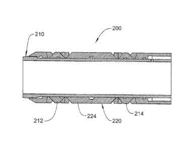
[0020] A packer, formed in accordance with an exemplary embodiment, is
illustrated
generally at 200 in FIG. 1. Packer 200 is supported by a tubular 210 between a
first wedge
ring 212 and a second wedge ring 214. It is to be understood that the
particular type of
wedge ring may vary. It is to be further understood that additional rings,
such as edge c-rings
and grooved C-rings, may also be employed. As shown in FIG. 12, Packer 200
includes a
body 220 formed from an elastic composite material 224 having an elastic
structure with
filler materials as described below. The elastic structure may take the form
of a one-
dimensional elastic structure, a periodic elastic structure such as described
in U.S. Patent
Application No. 14/548,610, entitled "PERIODIC STRUCTURED COMPOSITE AND
ARTICLES THEREFROM", filed on November 20, 2014, or a random elastic structure
such
as described in U.S. Patent Application No. 14/676,864, entitled "ULTRAHIGH
TEMPERATURE ELASTIC METAL COMPOSITES", filed on April 2, 2015.
[0021] It is to be understood that the phrase "elastic structure" means that
the
structure has greater than about 50% elastic deformation, greater than about
80% elastic
deformation, greater than about 100% elastic deformation, or greater than
about 200% of
elastic defoiniation. A percentage of elastic deformation can be calculated by
AL/L, where
AL is the recoverable change in a dimension as a result of a tensile or
compressive stress, and
L is the original dimension length. As used herein, the phrase "one-
dimensional structure"
refers to a structure that can extend continuously in one direction.
[0022] The elastic structure may comprise a porous matrix material and can be
formed from a wire. The wire can have a diameter of about 0.08 to about 0.5
mm. The
cross-section of the wire is not particularly limited. Exemplary cross-
sections include circle,
triangle, rectangle, square, oval, star and the like. The wire can be hollow.
[0023] The patterns of the one-dimensional elastic structure are not
particularly
limited as long as they provide the desired elasticity. Exemplary patterns
include springs as
shown in FIGS. 2A-2C. The shapes of the coils of the springs are not
particularly limited. In
FIGS 2A-2C the coils of the springs have a shape of circle, square, and
triangle respectively.
3
Date Recue/Date Received 2020-07-16
CA 03041613 2019-04-24
WO 2018/080716 PCT/1JS2017/053989
Other shapes are contemplated. The pattern can also have a planar structure as
illustrated in
FIGS. 3A-3C.
[0024] In a specific embodiment, the elastic composite material comprises a
one-
dimensional elastic structure such as a spring. The spring can have an average
spring pitch of
about 10 to about 15 times of the wire diameter, where the pitch of a spring
refers to the
distance from the center of one coil to the center of the adjacent coil. The
average spring
diameter is also about 10 to about 15 times of the wire diameter. As used
herein, spring
diameter refers to the outside diameter of the coil minus one wire diameter
(d). Such a spring
diameter is also commonly known as mean coil diameter. In an embodiment, the
springs
have an average spring pitch of about 0.8 to about 7.5 mm and an average
spring diameter of
about 0.8 to about 7.5 mm. The springs can have a density of about 0.2 to
about 4 g/cm3. In
an exemplary embodiment, the springs are hollow members that have a wall
thickness
ranging from tens of nanometers to tens of microns (10 nanometers to 90
microns). In certain
embodiments, the springs are solid members. The springs may be formed from a
wire
comprising stainless-steel.
[0025] The form and shape of the fillers are not particularly limited. The
fillers can
comprise a solid piece in the form of a tube, a rod, or the like. The fillers
can also be in the
form of a coating, a powder or pellets. FIGS. 4A-4C illustrate filler filled
one-dimensional
elastic structures according to various embodiments of the disclosure. In FIG.
4A the filled
one-dimensional elastic structure comprises a spring 1 wound around a filler
rod 2; in FIG.
4B, the filler 72 is in the form of a powder disposed inside the coils of a
spring 71; and in
FIG. 4C, the filler 82 comprises pellets disclosed inside the coils of a
spring 81.
[0026] In an embodiment, the one-dimensional elastic structure at least
partially
encompasses the filler. For example, the filler can occupy the entire open
space inside the
coils of the springs or occupy a portion of the open space insider the coils
of the springs. The
filler can be in partial, full, or no contact with the one-dimensional elastic
structure. In
another embodiment, the filler is coated on the one-dimensional elastic
structure.
[0027] The one-dimensional elastic structure can be used to form a sheet. The
method is not particularly limited and includes bending, stacking, aligning,
knotting the one-
dimensional elastic structures, or a combination comprising at least one of
the foregoing.
FIG. 5 illustrates a method of preparing a sheet according to an embodiment of
the
disclosure; and FIG. 6 illustrates a method of preparing a sheet according to
another
embodiment of the disclosure. In FIG. 5, one-dimensional elastic structure 11
is wound
around pin 15 according to a preset pattern to form a sheet having a periodic
elastic structure.
4
CA 03041613 2019-04-24
WO 2018/080716 PCMJS2017/053989
In FIG. 6, a one-dimensional elastic structure 21 is wound around pin 25
according to another
preset pattern to form a sheet having a periodic elastic structure. Pins can
be removed after
the sheets are formed. Similarly, a two-dimensional filled sheet (not shown)
can be formed
with one-dimensional elastic structures.
[0028] Similar to the composite orientation labeling, a standard orientation
code can
be used to define the orientations of the elastic structures. In the instant
where the one-
dimensional elastic structure comprises springs, the orientation code denotes
the angle, in
degrees, between the spring coil axial direction and the "X" axis of an
article made from the
elastic structure. The "X" axis of the article can be a randomly chosen
reference axis. The
springs may be orientated in any angles with respect to the X-axis (00).
[0029] In an embodiment, the filler filled, or unfilled, one-dimensional
spring in a
given sheet is oriented in the same direction. In another embodiment, the one-
dimensional
spring in a given sheet is oriented in more than one direction. For example in
FIGS. 7A, 7B
and 7C, the spring orientations are denoted as [0, 90, +45, -45], [+45,-45],
and [0, 90]
respectively, where the orientations are separated by comma a (,). The plus
(+) and minus (-)
angles are relative to the "X" axis. Plus (+) signs are to the left of zero,
and minus (¨) signs
are to the right of zero. In these figures, straight lines 31, 41, and 51
represent filler filled
springs. The springs may also be laid in random directions within one sheet,
as shown in
FIG. 7D.
[0030] The sheets can be used to form the preform. Methods are not
particularly
limited and include bending, folding, or rolling the sheet, stacking multiple
sheets together or
a combination comprising at least one of the foregoing.
[0031] When multiple sheets are stacked together, the one-dimensional elastic
structures in each layer can have the same or different orientation profiles.
FIG. 8A
illustrates a preform containing four layers of filled sheets (96) containing
springs orientated
at 0 C, 900, +450 and -450 respectively in each layer. FIG. 8B illustrates a
preform containing
two layers of filled sheets (106) where the top layer contains springs
orientated at +450 and -
450 and the bottom layer contains springs oriented at 0 and 90 . Similarly,
multiple filler-
filled sheets may be stacked together.
[0032] As shown in FIGS. 9A and 9B, the filled sheet 116 or 126 can be rolled
along
the arrow direction to form the preform, except that the method illustrated in
FIG. 9A does
not have a mandrel whereas the method illustrated in FIG. 9B uses a mandrel
127.
[0033] Although the preform can be formed from a sheet, which is in turn
formed
from a one-dimensional elastic structure, it is appreciated that the preform
can be formed
CA 03041613 2019-04-24
WO 2018/080716 PCT/1JS2017/053989
directly from the one-dimensional structure without forming a sheet first. The
method is not
particularly limited and includes bending, knotting, stacking the one-
dimensional elastic
structure and the like. Further, it should be understood that the preform can
be formed from a
filled sheet, which is in turn formed from a filler-filled one-dimensional
elastic structure in a
manner similar to that described above.
[0034] In another embodiment, a method of manufacturing an elastic composite
comprises forming a preform comprising alternating layers of a matrix layer
and a filler layer;
the matrix layer comprising a periodic structure network formed from a matrix
material; and
the filler layer comprising a filler material; molding the preform to form a
molded product;
and sintering the molded product to provide the elastic composite.
[0035] The matrix layer can be formed from a filler filled one-dimensional
elastic
structure as described herein or an unfilled one-dimensional elastic
structure, or a
combination thereof In an embodiment, the unfilled one-dimensional elastic
structures can
have the same average spring pitch, same average spring diameter, and same
wire diameter as
the springs described herein in the context of filler filled one-dimensional
elastic structure.
Methods to form the matrix layer are not particularly limited and includes
bending, aligning,
stacking, knotting the one-dimensional elastic structures, or a combination
comprising at least
one of the foregoing. Methods illustrated in FIGS. 5 and 6 can also be used to
make matrix
layers. In a specific embodiment, a periodic structure network may comprise
periodic
springs.
[0036] The orientations of the springs in one matrix layer as well as the
orientations
of springs in different matrix layers can be the same as described herein in
the context of the
filled sheets and the preforms made from filler filled one-dimensional elastic
structures. The
teints layers and sheets are used interchangeably herein.
[0037] As used herein, alternating layers of a matrix layer and a filler layer
comprise
at least one matrix layer and at least one filler layer. One exemplary preform
is illustrated in
FIG. 10, which contains multiple matrix layers 81 and multiple filler layers
82. The preform
can be used directly in the molding and sintering process. Alternatively the
preform can be
further rolled, folded, or bended before it is compressed and sintered. If
desirable, additional
filler can be impregnated into the preform.
[0038] In another embodiment, a method of manufacturing an elastic composite
comprises forming a matrix layer from an unfilled one-dimensional elastic
structure; bending;
folding; rolling; or stacking the matrix layer; and combining the matrix layer
with a filler
material to form a preform It is appreciated that the filler can be in the
form of a powder,
6
gel, liquid and the like. The filler can be combined with the matrix material
before the matrix
layer is further bended, folded, rolled, or stacked or after the matrix layer
is bended, folded,
rolled, or stacked. The combination method includes impregnation,
infiltration, or other
processes known in the art.
[0039] The preform can be compression molded, sintered, and/or hot isostatic
pressed
to form the elastic composite. In an embodiment, the method comprises molding
the preform
to provide a molded product; and sintering the molded product to form the
elastic composite.
Molding is conducted at a pressure of about 500 psi to about 50,000 psi and a
molding
temperature of about 20 C to about 30 C. Sintering is carried out at a
temperature greater
than about 150 C but lower than the melting points of the filler material and
the matrix
material. A pressure of about 500 psi to about 50,000 psi is optionally
applied during the
sintering process.
[0040] Optionally the method further comprises heating the elastic composite
at an
elevated temperature and atmospheric pressure to release residual stress. In
an embodiment,
the heating temperature is about 20 to 50 C lower than the sintering
temperature to make the
elastic composite. In the instance where the filler is a polymer, the post
treatment
temperature is about 20 C to about 300 C or about 20 C to about 200 C.
[0041] As used herein, a "matrix material" refers to a material that forms a
pattern or
structure providing elasticity to the composite. The matrix material comprises
one or more of
the following: a metal; a metal alloy; a carbide; a ceramic; or a polymer or
combinations
thereof. In an embodiment, the matrix material comprises a metal or a
corrosion resistant
metal alloy. Exemplary matrix material includes one or more of the following:
an iron alloy,
a nickel-chromium based alloy, a nickel alloy, copper, or a shape memory
alloy. An iron
alloy includes steel such as stainless steel. Nickel-chromium based alloys
include
INCONELTM. Nickel-chromium based alloys can contain about 40-75% of Ni and
about 10-
35% of Cr. The nickel-chromium based alloys can also contain about 1 to about
15% of iron.
Small amounts of Mo, Nb, Co, Mn, Cu, Al, Ti, Si, C, S, P, B, or a combination
comprising at
least one of the foregoing can also be included in the nickel-chromium based
alloys. Nickel
alloy includes HASTELLOY'. Hastelloy is a trademarked name of Haynes
International,
Inc'. As used herein, Hastelloy can be any of the highly corrosion-resistant
superalloys
having the "Hastelloy" trademark as a prefix. The primary element of the
HASTELLOY
group of alloys referred to in the disclosure is nickel; however, other
alloying ingredients are
added to nickel in each of the subcategories of this trademark designation and
include varying
percentages of the elements molybdenum, chromium, cobalt, iron, copper,
manganese,
titanium, zirconium,
7
Date Recue/Date Received 2020-07-16
CA 03041613 2019-04-24
WO 2018/080716 PCMJS2017/053989
aluminum, carbon, and tungsten. Shape memory alloy is an alloy that
"remembers" its
original shape and that when deformed returns to its pre-deformed shape when
heated.
Exemplary shape memory alloys include Cu-Al-Ni based alloys, Ni-Ti based
alloys, Zn-Cu-
Au-Fe based alloys, and iron-based and copper-based shape memory alloys, such
as Fe-Mn-
Si, Cu-Zn-Al and Cu-Al-Ni.
[0042] Exemplary polymers for the matrix material include elastomers such as
acrylonitrile butadiene rubber (NBR); hydrogenated nitrile butadiene (I-INBR);
acrylonitrile
butadiene carboxy monomer (XNBR); ethylene propylene diene monomer (EPDM);
fluorocarbon rubber (FKM); perfluorocarbon rubber (FFKM); tetrafluoro
ethylene/propylene
rubbers (FEPM); silicone rubber and polyurethane (PU); thermoplastics such as
nylon,
polyethylene (PE), polytetrafluoroethylene (PTFE); perfluoroalkoxy alkane
(PFA),
polyphenylene sulfide (PPS) polyether ether ketone (PEEK); polyphenylsulfone
(PPSU);
polyimide (PI), polyethylene tetraphthalate (PET) or polycarbonate (PC).
[0043] Exemplary carbides for the matrix material include a carbide of
aluminum,
titanium, nickel, tungsten, chromium, iron, an aluminum alloy, a copper alloy,
a titanium
alloy, a nickel alloy, a tungsten alloy, a chromium alloy, or an iron alloy,
SiC, B4C.
[0044] Advantageously, the filler materials may enhance the sealing
characteristics of
the elastic structures such as metal springs while providing additional
strength and rigidity.
The filler materials can have similar or complimentary elastic properties of
the elastic
structures such as metal springs. Optionally the filler material has a high
temperature rating.
The filler materials in the elastic composites comprise a carbon composite; a
polymer; a
metal; graphite; cotton; asbestos; or glass fibers. Although there may be
overlaps between
the materials that can be used as a filler and a matrix material, it is
appreciated that in a given
elastic composite, the filler and the matrix material are compositionally
different.
Combinations of the materials can be used. The filler material can be a
sintered material or a
non-sintered material. Optionally the filler materials contain reinforcement
fibers, the
reinforcement fibers being oriented in short, long, or continuous fibers,
beads, or balloons.
The volume ratio between the filler material and the metal matrix can vary
depending on the
applications. In an embodiment, the volume ratio of the matrix material
relative to the filler
material is about 2.5% : 97.5% to about 80% : 20%, about 5% : 95% to about 70%
: 30%, or
about 10%: 90% to about 60%: 40%.
[0045] When the filler material is a carbon composite, the elastic composite
can have
a temperature rating of greater than about 600 C. Carbon composites contain
carbon and an
inorganic binder. The carbon can be graphite such as natural graphite;
synthetic graphite;
8
CA 03041613 2019-04-24
WO 2018/080716 PCMJS2017/053989
expandable graphite; or expanded graphite; or a combination comprising at
least one of the
foregoing.
[0046] In an embodiment, the carbon composites comprise carbon microstructures
haying interstitial spaces among the carbon microstructures; wherein the
binder is disposed in
at least some of the interstitial spaces. The interstitial spaces among the
carbon
microstructures have a size of about 0.1 to about 100 microns, specifically
about 1 to about
20 microns. A binder can occupy about 10% to about 90% of the interstitial
spaces among
the carbon microstructures
[0047] The carbon microstructures can also comprise voids within the carbon
microstructures. The voids within the carbon microstructures are generally
between about 20
nanometers to about 1 micron, specifically about 200 nanometers to about 1
micron. As used
herein, the size of the voids or interstitial spaces refers to the largest
dimension of the voids
or interstitial spaces and can be determined by high resolution electron or
atomic force
microscope technology. In an embodiment, to achieve high strength, the voids
within the
carbon microstructures are filled with the binder or a derivative thereof
Methods to fill the
voids within the carbon microstructures include vapor deposition.
[0048] The carbon microstructures are microscopic structures of graphite
formed after
compressing graphite into highly condensed state. They comprise graphite basal
planes
stacked together along the compression direction. As used herein, carbon basal
planes refer
to substantially flat, parallel sheets or layers of carbon atoms, where each
sheet or layer has a
single atom thickness. The graphite basal planes are also referred to as
carbon layers. The
carbon microstructures are generally flat and thin. They can have different
shapes and can
also be referred to as micro-flakes, micro-discs and the like. In an
embodiment, the carbon
microstructures are substantially parallel to each other.
[0049] The carbon microstructures have a thickness of about 1 to about 200
microns,
about 1 to about 150 microns, about 1 to about 100 microns, about 1 to about
50 microns, or
about 10 to about 20 microns. The diameter or largest dimension of the carbon
microstructures is about 5 to about 500 microns or about 10 to about 500
microns. The
aspect ratio of the carbon microstructures can be about 10 to about 500, about
20 to about
400, or about 25 to about 350. In an embodiment, the distance between the
carbon layers in
the carbon microstructures is about 0.3 nanometers to about 1 micron. The
carbon
microstructures can have a density of about 0.5 to about 3 &in', or about 0.1
to about 2
g/cm3.
9
[0050] In the carbon composites, the carbon microstructures are held together
by a
binding phase. The binding phase comprises a binder that binds carbon
microstructures by
mechanical interlocking. Optionally, an interface layer is formed between the
binder and the
carbon microstructures. The interface layer can comprise chemical bonds, solid
solutions, or
a combination thereof. When present, the chemical bonds, solid solutions, or a
combination
thereof may strengthen the interlocking of the carbon microstructures. It is
appreciated that
the carbon microstructures may be held together by both mechanical
interlocking and
chemical bonding. For example the chemical bonding, solid solution, or a
combination
thereof may be formed between some carbon microstructures and the binder or
for a
particular carbon microstructure only between a portion of the carbon on the
surface of the
carbon microstructure and the binder. For the carbon microstructures or
portions of the
carbon microstructures that do not form a chemical bond, solid solution, or a
combination
thereof, the carbon microstructures can be bounded by mechanical interlocking.
The
thickness of the binding phase is about 0.1 to about 100 microns or about 1 to
about 20
microns. The binding phase can form a continuous or discontinuous network that
binds
carbon microstructures together.
[0051] Exemplary binders include a nonmetal, a metal, an alloy, or a
combination
comprising at least one of the foregoing. The nonmetal is one or more of the
following: SiO2;
Si; B; or B203. The metal can be at least one of aluminum; copper; titanium;
nickel;
tungsten; chromium; iron; manganese; zirconium; hafnium; vanadium; niobium;
molybdenum; tin; bismuth; antimony; lead; cadmium; or selenium. The alloy
includes one or
more of the following: aluminum alloys; copper alloys; titanium alloys; nickel
alloys;
tungsten alloys; chromium alloys; iron alloys; manganese alloys; zirconium
alloys; hafnium
alloys; vanadium alloys; niobium alloys; molybdenum alloys; tin alloys;
bismuth alloys;
antimony alloys; lead alloys; cadmium alloys; or selenium alloys. In an
embodiment, the
binder comprises one or more of the following: copper; nickel; chromium; iron;
titanium; an
alloy of copper; an alloy of nickel; an alloy of chromium; an alloy of iron;
or an alloy of
titanium. Exemplary alloys include steel, nickel-chromium based alloys such as
InconelTM,
and nickel-copper based alloys such as MonelTM alloys. Nickel-chromium based
alloys can
contain about 40-75% of Ni and about 10-35% of Cr. The nickel-chromium based
alloys can
also contain about 1 to about 15% of iron. Small amounts of Mo, Nb, Co, Mn,
Cu, Al, Ti, Si,
C, S, P, B, or a combination comprising at least one of the foregoing can also
be included in
the nickel-chromium based alloys. Nickel-copper based alloys are primarily
composed of
nickel (up to about 67%) and copper. The nickel-copper based alloys can also
contain small
Date Recue/Date Received 2020-07-16
CA 03041613 2019-04-24
WO 2018/080716 PCMJS2017/053989
amounts of iron, manganese, carbon, and silicon. These materials can be in
different shapes,
such as particles, fibers, and wires. Combinations of the materials can be
used.
[0052] The binder used to make the carbon composite is micro- or nano-sized.
In an
embodiment, the binder has an average particle size of about 0.05 to about 250
microns,
about 0.05 to about 100 microns, about 0.05 to about 50 microns, or about 0.05
to about 10
microns. Without wishing to be bound by theory, it is believed that when the
binder has a
size within these ranges, it disperses uniformly among the carbon
microstructures.
[0053] When an interface layer is present, the binding phase comprises a
binder layer
comprising a binder and an interface layer bonding one of the at least two
carbon
microstructures to the binder layer. In an embodiment, the binding phase
comprises a binder
layer, a first interface layer bonding one of the carbon microstructures to
the binder layer, and
a second interface layer bonding the other of the at least two microstructures
to the binder
layer. The first interface layer and the second interface layer can have the
same or different
compositions.
[0054] The interface layer comprises one or more of the following: a C-metal
bond; a
C-B bond; a C-Si bond; a C-O-Si bond; a C-0-metal bond; or a metal carbon
solution. The
bonds are formed from the carbon on the surface of the carbon microstructures
and the
binder.
[0055] In an embodiment, the interface layer comprises carbides of the binder.
The
carbides include one or more of the following: carbides of aluminum; carbides
of titanium;
carbides of nickel; carbides of tungsten; carbides of chromium; carbides of
iron; carbides of
manganese; carbides of zirconium; carbides of hafnium; carbides of vanadium;
carbides of
niobium; or carbides of molybdenum. These carbides are formed by reacting the
corresponding metal or metal alloy binder with the carbon atoms of the carbon
microstructures. The binding phase can also comprise SiC formed by reacting
SiO2 or Si
with the carbon of carbon microstructures, or B4C formed by reacting B or B203
with the
carbon of the carbon microstructures. When a combination of binder materials
is used, the
interface layer can comprise a combination of these carbides. The carbides can
be salt-like
carbides such as aluminum carbide, covalent carbides such as SiC and B4C,
interstitial
carbides such as carbides of the group 4, 5, and 6 transition metals, or
intermediate transition
metal carbides, for example the carbides of Cr, Mn, Fe, Co, and Ni.
[0056] In another embodiment, the interface layer comprises a solid solution
of
carbon such as graphite and a binder. Carbon has solubility in certain metal
matrix or at
certain temperature ranges, which can facilitate both wetting and binding of a
metal phase
11
CA 03041613 2019-04-24
WO 2018/080716 PCMJS2017/053989
onto the carbon microstructures. Through heat-treatment, high solubility of
carbon in metal
can be maintained at low temperatures. These metals include one or more of Co,
Fe; La, Mn;
Ni; or Cu. The binder layer can also comprise a combination of solid solutions
and carbides.
[0057] The carbon composites comprise about 20 to about 95 wt. %, about 20 to
about 80 wt. %, or about 50 to about 80 wt. % of carbon, based on the total
weight of the
composites. The binder is present in an amount of about 5 wt. % to about 75
wt. % or about
20 wt. % to about 50 wt. %, based on the total weight of the composites. In
the carbon
composites, the weight ratio of carbon relative to the binder is about 1:4 to
about 20:1, or
about 1:4 to about 4:1, or about 1:1 to about 4:1.
[0058] The carbon composites can optionally comprise a reinforcing agent.
Exemplary reinforcing agent includes one or more of the following: carbon
fibers; carbon
black; mica; clay; glass fibers; ceramic fibers; or ceramic hollow structures.
Ceramic
materials include SiC, Si3N4, SiO2, BN, and the like. The reinforcing agent
can be present in
an amount of about 0.5 to about 10 wt. % or about 1 to about 8%, based on the
total weight of
the carbon composite.
[0059] Filler materials other than carbon composites can also be used in the
elastic
composites of the disclosure. Other suitable filler materials for the elastic
composites include
a soft metal, soft metal alloy, or a combination comprising one or more of the
foregoing.
Exemplary metals for the filler material include one or more of the following:
aluminum;
copper; lead; bismuth; gallium; cadmium; silver; gold; rhodium; thallium; tin;
alloys thereof;
or a eutectic alloy. A eutectic alloy is one for which the melting point is as
low as possible
and all the constituents of the alloy crystallize simultaneously at this
temperature from the
liquid state.
[0060] The filler materials for the elastic composites can also be a polymer
such as a
thermosetting polymer, a thermoplastic polymer or a combination comprising at
least one of
the foregoing. As used herein, polymers include both synthetic polymers and
natural
polymers. Polymers also include crosslinked polymers. When the filler material
is a
polymer, the elastic composite can have a recoverable deformation of greater
than about
30%.
[0061] Exemplary polymers for the filler material include elastomers such as
acrylonitrile butadiene rubber (NBR); hydrogenated nitrile butadiene (HNBR);
acrylonitrile
butadiene carboxy monomer (XNBR); ethylene propylene diene monomer (EPDM);
fluorocarbon rubber (FKM); perfluorocarbon rubber (FFKM); tetrafluoro
ethylene/propylene
rubbers (FEPM); silicone rubber and polyurethane (PU); thermoplastics such as
nylon,
12
CA 03041613 2019-04-24
WO 2018/080716 PCMJS2017/053989
polyethylene (PE), polytetrafluoroethylene (PTFE); perfluoroalkoxy alkane
(PFA),
polyphenylene sulfide (PPS) polyether ether ketone (PEEK); polyphenylsulfone
(PPSU),
polyimide (PI), polyethylene tetraphthalate (PET) or polycarbonate (PC). In a
specific
embodiment, the filler comprises polytetrafluoroethylene.
[0062] The filler materials are bounded to the matrix materials/structures via
mechanical interlocking; or chemical bonding; either directly or through an
active interface
layer between the surfaces of the matrix materials/structures and the filler
materials. As used
herein, the term "matrix structures" refer to the structures formed from the
matrix materials.
The binding between matrix materials/structures and filler materials
facilitates transferring
loads between the matrix and the filler. Advantageously, optimum binding
allows for
compatibility and integrity of the different materials of matrix and the
filler under loading
conditions. Weak interfacial bounding may not be sufficient for load
distribution and
transformation as delamination or cracks may occur and destroy the integrity
of the
composite, while excessive interfacial bounding may lead to a rigid composite,
which
compromises the elasticity of the matrix.
[0063] When the filler materials comprise a carbon composite or a metal, the
filler
materials can be bounded to the matrix materials/structures via at least one
of a solid solution
or intermetallic compounds formed between the metal in the matrix material and
the metal in
the filler material. Advantageously, a solid solution is formed providing
robust binding
between the filler material and the matrix material. When the filler materials
comprise a
polymer, the filler materials can be bounded to the matrix material/structure
through
mechanical interlocking
[0064] The elastic composites are useful for preparing articles for a wide
variety of
applications. The elastic composites may be used to form all or a portion of
an article such as
packer 200. Packer 200 may form part of a resource exploration system, in
accordance with
an exemplary embodiment, is indicated generally at 232, in FIG. 11. Resource
exploration
system 232 should be understood to include well drilling operations, resource
extraction and
recovery, CO2 sequestration, and the like. Resource exploration system 232 may
include a
surface system 234 operatively connected to a downhole system 236. Surface
system 234
may include pumps 238 that aid in completion and/or extraction processes as
well as fluid
storage 240. Fluid storage 240 may contain a gravel pack fluid or slurry (not
shown) that is
introduced into downhole system 236.
[0065] Downhole system 236 may include a plurality of tubulars 250 that are
extended into a borehole 251 formed in formation 252. While borehole 251 is
shown as an
13
CA 03041613 2019-04-24
WO 2018/080716 PCMJS2017/053989
open hole, it is to be understood that packer 200 may be deployable in cased
boreholes.
Plurality of tubulars 250 may be formed from a number of connected downhole
tools or
tubulars 254 that include tubular 210. In accordance with an exemplary aspect,
packer 200
may be deployed to segregate borehole into multiple zones. Packer 200 may be
deployed
downhole in high temperature applications. The term "high temperature" should
be
understood to describe temperatures that exceed 450 F (232 C). For example,
packer 200
may be deployable in conditions where downhole temperatures exceed 500 F (260
C). That
is, the exemplary embodiments describe a packer having an elastic structure
that is capable of
high temperature/high pressure deployment.
[0066] Packer 200 formed from an elastic composite material 224 possesses high
extrusion resistance and thus is capable of holding or supporting pressures up
to about 2000
psi (13.78) and greater. For example, in addition to being deployable in high
temperature
conditions, packer 200 supports pressures of at least 2000 psi when exposed to
high
temperature conditions. Elastic composite material 224 may include one of a
one-
dimensional elastic structure, a periodic elastic structure, and a random
elastic structure. The
elastic composite employed to form material 224 also possesses high expansion
capabilities.
[0067] For example, packer 200 may expand to 6.79-inch (17.25-cm) when formed
with a 0.65-inch (16.51-mm) thickness and a 5.75-inch (14.6-cm) OD. Elastic
composite
material 224 also provides increased corrosion resistance resulting from
included corrosion
resistant filler material and springs that may be formed from stainless steel.
It is to be
understood that packer 200 may be formed through a variety of processes
including molding,
extrusion, and the like. Further, it is to be understood that packer 200 may
be formed of a
plurality of packer segments (not shown). These segments may be the same or
different in
Willis of filler materials, elastic structures, dimensions (thickness) or
shapes, densities, etc.
according to the desired applications.
[0068] In further accordance with an exemplary embodiment, elastic composite
material 224 possess enhanced extrusion resistance. For example, a compressive
load of up
to 30,000 lbf (13.7 if) applied to extrude elastic composite material 224
through a 0.0030-
inch (0.0762-mm) gap at a temperature of 550 F (287.8 C) resulted in a
displacement of less
than 0.2-inches (5.1 mm)
[0069] In accordance with an aspect of an exemplary embodiment illustrated in
FIG.
13, a packer 300 may include a body 320 formed from an elastic composite
material 324.
Body 320 may include an axially extending groove 330. Groove 330 may be
receptive to a
filler ring (not shown). Elastic composite material 324 may include one of a
one-dimensional
14
CA 03041613 2019-04-24
WO 2018/080716 PCMJS2017/053989
elastic structure, a periodic elastic structure, and a random elastic
structure as described
above. The elastic structure of elastic composite material 324 provides
increased corrosion
resistance resulting from corrosion resistant material and springs that may be
formed from
stainless steel. It is to be understood that packer 300 may be formed through
a variety of
processes including molding, extrusion, and the like.
[0070] In a manner similar to that described above, the elastic structure of
elastic
composite material 324 possess high extrusion resistance and thus is capable
of holding or
supporting pressures up to about 2000 psi (13.78114Pa) and greater. In a
manner also similar
to that described above, packer 300, may be deployed in high temperature
conditions. In an
example, packer 300 supports pressures of at least 2000 psi when exposed to
temperatures
that may exceed 450 F (232 C). The one-dimensional elastic structure of
material 324 also
possesses high expansion capabilities.
[0071] Further included in this disclosure are the following specific
embodiments,
which do not necessarily limit the claims.
[0072] Embodiment 1: A packer comprising: a body formed from an elastic
composite material having one of a one-dimensional elastic structure, a
periodic elastic
structure, and a random elastic structure and a filler material.
[0073] Embodiment 2: The packer according to embodiment 1, wherein the filler
material includes one or more of a carbon composite; a polymer; a metal;
graphite; cotton;
asbestos; and glass fibers.
[0074] Embodiment 3: The packer according to embodiment 2, wherein the filler
material comprises a carbon composite having carbon microstructures including
a plurality of
interstitial spaces and a binder provided in one or more of the plurality of
interstitial spaces.
[0075] Embodiment 4: The packer according to embodiment 3, wherein the binder
is
provided in between about 100/0 to about 90 % of the plurality of interstitial
spaces.
[0076] Embodiment 5: The packer according to embodiment 3, wherein the carbon
microstructures have a size of between about 0.1 to about 100 microns.
[0077] Embodiment 6: The packer according to embodiment 1, wherein the filler
material is one of a sintered material and a non-sintered material.
[0078] Embodiment 7: The packer according to embodiment 1, wherein the filler
material comprises between about 20% to about 97.5% of the body.
[0079] Embodiment 8: The packer according to embodiment 1, wherein the body
comprises a one-dimensional elastic structure including at least one of a
solid tube, a solid
rod a coating, a powder, a plurality of pellets.
CA 03041613 2019-04-24
WO 2018/080716
PCMJS2017/053989
[0080] Embodiment 9: The packer according to embodiment 1, wherein the one-
dimensional elastic structure comprises a spring.
[0081] Embodiment 10: The packer according to embodiment 1, wherein the body
formed from the elastic composite material having the periodic elastic
structure.
[0082] Embodiment 11: The packer according to embodiment 1, wherein the body
is
supportable of pressures of at least 2000 psi (13.78 MPa) at temperatures
exceeding 450 F
(232 C).
[0083] Embodiment 12: A resource exploration/recovery system comprising: a
surface portion; and a downhole portion including a plurality of tubulars, at
least one of the
plurality of tubulars including a packer comprising a body formed from an
elastic composite
material having one of a one-dimensional elastic structure, a periodic elastic
structure, and a
random elastic structure.
[0084] Embodiment 13: The resource exploration/recovery system according to
embodiment 12, wherein the filler material includes one or more of a carbon
composite; a
polymer; a metal; graphite; cotton; asbestos; and glass fibers.
[0085] Embodiment 14: The resource exploration/recovery system according to
embodiment 13, wherein the filler material comprises a carbon composite having
carbon
microstructures including a plurality of interstitial spaces and a binder
provided in one or
more of the plurality of interstitial spaces.
[0086] Embodiment 15: The resource exploration/recovery system according to
embodiment 12, wherein the filler material is one of a sintered material and a
non-sintered
material.
[0087] Embodiment 16: The resource exploration/recovery system according to
embodiment 12, wherein the body formed from the elastic composite material
having the
periodic elastic structure.
[0088] Embodiment 17: The resource exploration/recovery system according to
embodiment 12, wherein the body is supportable of pressures of at least 2000
psi (13.78
MPa) at temperatures exceeding 450 F (232 C).
[0089] Embodiment 18: A method of segregating a borehole into multiple zones
comprising: running a plurality of tubulars into the borehole; and deploying a
packer
comprising a body formed from an elastic composite material having one of a
one-
dimensional elastic structure, a periodic elastic structure, and a random
elastic structure
supported by one of the plurality of tubulars.
16
CA 03041613 2019-04-24
WO 2018/080716 PCMJS2017/053989
[0090] Embodiment 19: The method of embodiment 18, wherein deploying the
packer includes expanding the packer at a portion of the borehole having a
local temperature
of at least 450 F (232 C).
[0091] Embodiment 20: The method of embodiment 18, further comprising:
exposing the packer to a pressure of at least 2000 psi (13.78 MPA).
[0092] The teachings of the present disclosure may be used in a variety of
well
operations. These operations may involve using one or more treatment agents to
treat a
formation, the fluids resident in a formation, a borehole, and/or equipment in
the borehole,
such as production tubing. The treatment agents may be in the form of liquids,
gases, solids,
semi-solids, and mixtures thereof Illustrative treatment agents include, but
are not limited to,
fracturing fluids, acids, steam, water, brine, anti-corrosion agents, cement,
permeability
modifiers, drilling muds, emulsifiers, demulsifiers, tracers, flow improvers
etc. Illustrative
well operations include, but are not limited to, hydraulic fracturing,
stimulation, tracer
injection, cleaning, acidizing, steam injection, water flooding, cementing,
etc.
[0093] The terms "about" and "substantially" unless otherwise defined are
intended to
include the degree of error associated with measurement of the particular
quantity based upon
the equipment available at the time of filing the application. For example,
"about" and
"substantially" can include a range of 8% or 5%, or 2% of a given value.
[0094] While one or more embodiments have been shown and described,
modifications and substitutions may be made thereto without departing from the
spirit and
scope of the invention. Accordingly, it is to be understood that the present
invention has been
described by way of illustrations and not limitation.
17