Note: Descriptions are shown in the official language in which they were submitted.
CA 03042021 2019-04-26
WO 2018/080965
PCT/US2017/057811
1
FLEXIBLE RADIO-OPAQUE PROTRUSIONS FOR REVEALING
THE POSITION OF A CONSTRICTING CORD OR ANNULUS RING
PRIOR TO INSTALLATION ONTO A CARDIAC VALVE ANNULUS
CROSS REFERENCE TO RELATED APPLICATIONS
[0001] This Application claims the benefit of US Provisional Application
62/415,414,
filed October 31, 2016, which is incorporated herein by reference in its
entirety.
BACKGROUND
[0002] A variety of approaches for delivering and installing a
constricting cord (also
referred to as a cinching cord) or an annulus ring to a cardiac valve annulus
are described in
US applications 14/364,060 (published as US 2014/0309730) and 14/895,711
(published as
US 2016/0120645), each of which is incorporated by reference herein in its
entirety.
SUMMARY OF THE INVENTION
[0003] One aspect of the invention is directed to a first apparatus for
affixing a cord
to an annulus. The first apparatus comprises a cord having a distal loop
portion, and at least
four anchors distributed about the cord. Each of the at least four anchors is
configured to
anchor a respective region of the cord to the annulus or to tissue adjacent to
the annulus. The
first apparatus also comprises at least four anchor launchers, at least four
support arms, and at
least four flexible radio-opaque protrusions. Each of the anchor launchers has
a distal end,
and each of the anchor launchers is configured to launch a respective one of
the at least four
anchors out of the anchor launcher's distal end so that the respective anchor
becomes
embedded in the annulus or the tissue adjacent to the annulus. Each of the
support arms is
shaped and arranged to support a respective one of the at least four anchor
launchers so that
the at least four support arms hold the distal ends of the anchor launchers at
positions that
correspond to a shape of the annulus, with the distal ends of the anchor
launchers distributed
about a perimeter of the shape of the annulus. Each of the protrusions is
arranged with respect
to a respective one of the at least four anchor launchers so that the
protrusion is free to move
from a relaxed state to a deflected state. In the relaxed state the protrusion
protrudes distally
beyond the distal end of the respective anchor launcher. Each of the
protrusions is shaped and
arranged so that progressive advancement of the respective anchor launcher in
a distal
direction beyond a point at which the protrusion makes contact with the
annulus or the tissue
adjacent to the annulus results in progressive deflection of the protrusion.
CA 03042021 2019-04-26
WO 2018/080965
PCT/US2017/057811
2
[0004] In some embodiments of the first apparatus, each of the
protrusions extends
between 4 and 10 mm from the distal end of the respective anchor launcher. In
some
embodiments of the first apparatus, each of the protrusions has a diameter
between 005 and
0.3 mm.
[0005] In some embodiments of the first apparatus, in the relaxed state,
each of the
protrusions is bent at an angle between 50 and 20 with respect to a
longitudinal axis of the
respective anchor launcher. In some of these embodiments, in the relaxed
state, each of the
protrusions bends away from a centroid of the at least four anchor launchers.
[0006] In some embodiments of the first apparatus, each of the anchor
launchers
comprises a metal housing that is visualizable using fluoroscopy.
[0007] In some embodiments of the first apparatus, each of the
protrusions is
arranged so that when a protrusion in the deflected state is moved to a
position at which the
protrusion is no longer being pressed against the annulus or the tissue
adjacent to the annulus,
the protrusion returns towards the relaxed state.
[0008] In some embodiments of the first apparatus, each of the at least
four anchor
launchers comprises a housing shaped and dimensioned to accommodate a
respective one of
the at least four anchors, the housing having a distal end; a spring that is
movable between a
compressed state and an expanded state, arranged with respect to the housing
and the
respective anchor so that movement of the spring from the compressed state to
the expanded
state drives the respective anchor out of the distal end of the housing; and
an actuator
configured to trigger movement of the spring from the compressed state to the
expanded state
upon actuation of the actuator.
[0009] In some embodiments of the first apparatus, each of the
protrusions is affixed
to a respective anchor launcher by at least one weld. In some embodiments of
the first
apparatus, each of the protrusions is affixed to a respective pull wire that
is used to trigger a
respective anchor launcher.
[0010] In some embodiments of the first apparatus, the distal loop
portion of the cord
comprises an open loop having first and second ends, and the cord has first
and second
proximal portions connected, respectively, to the first and second ends of the
distal loop
CA 03042021 2019-04-26
WO 2018/080965
PCT/US2017/057811
3
portion. In other embodiments of the first apparatus, the distal loop portion
of the cord is a
closed loop.
[0011] Another aspect of the invention is directed to a first method for
affixing a cord
to an annulus. The first method comprises positioning, in a vicinity of the
annulus, (a) a cord
having a distal loop portion, (b) at least four anchors distributed about the
cord, wherein each
of the at least four anchors is configured to anchor a respective region of
the cord to the
annulus or to tissue adjacent to the annulus, (c) at least four anchor
launchers, each of the
anchor launchers having a distal end, wherein each of the anchor launchers is
configured to
launch a respective one of the at least four anchors out of the anchor
launcher's distal end so
that the respective anchor becomes embedded in the annulus or the tissue
adjacent to the
annulus, and (d) at least four flexible radio-opaque protrusions, wherein each
of the
protrusions is arranged with respect to a respective one of the at least four
anchor launchers
so that the protrusion is free to move from a relaxed state to a deflected
state. In the relaxed
state each of the protrusions protrudes distally beyond the distal end of the
respective anchor
launcher. Each of the protrusions is shaped and arranged so that progressive
advancement of
the respective anchor launcher in a distal direction beyond a point at which
the protrusion
makes contact with the annulus or the tissue adjacent to the annulus results
in progressive
deflection of the protrusion. The first method also comprises adjusting a
position of the
anchor launchers until fluoroscopic images of the protrusions indicate that
each of the
protrusions is deflected beyond a threshold angle; and triggering each of the
anchor launchers
to launch a respective anchor at a time when fluoroscopic images of the
protrusions indicate
that each of the protrusions is deflected beyond the threshold angle.
[0012] In some embodiments of the first method, each of the protrusions
extends
between 4 and 10 mm from the distal end of the respective anchor launcher. In
some
embodiments of the first method, each of the protrusions has a diameter
between 0.05 and 0.3
mm.
[0013] In some embodiments of the first method, each of the protrusions
is arranged
so that when a protrusion in the deflected state is moved to a position at
which the protrusion
is no longer being pressed against the annulus or the tissue adjacent to the
annulus, the
protrusion returns towards the relaxed state.
CA 03042021 2019-04-26
WO 2018/080965
PCT/US2017/057811
4
[0014] Another aspect of the invention is directed to a second method for
aligning a
device with a target location. The second method comprises arranging at least
three flexible
radio-opaque protrusions with respect to the device so that each of the
protrusions is free to
move from a relaxed state to a deflected state, wherein in the relaxed state
the protrusion
protrudes distally beyond the device, and wherein each of the protrusions is
shaped and
arranged so that progressive advancement of the device in a distal direction
beyond a point at
which the protrusion makes contact with a structure in the target location
results in
progressive deflection of the protrusion, and wherein each of the protrusions
is arranged so
that when a protrusion in the deflected state is moved to a position at which
the protrusion is
no longer being pressed against the structure, the protrusion returns towards
the relaxed state.
The second method also comprises positioning the device in a vicinity of the
target location;
adjusting a position of the device until fluoroscopic images of the
protrusions indicate that
each of the protrusions is deflected beyond a threshold angle; and releasing
the device at a
time when fluoroscopic images of the protrusions indicate that each of the
protrusions is
deflected beyond the threshold angle.
[0015] Some embodiments of the second method further comprise anchoring
the
device in place at the time when fluoroscopic images of the protrusions
indicate that each of
the protrusions is deflected beyond the threshold angle.
[0016] In some embodiments of the second method, each of the protrusions
extends
distally beyond the device by between 4 and 10 mm. In some embodiments of the
second
method, each of the protrusions has a diameter between 0.05 and 0.3 mm.
BRIEF DESCRIPTION OF THE DRAWINGS
[0017] FIGS. 1A and 1B are left and right side views, respectively, of an
embodiment
of an apparatus for installing a constricting cord or an annulus ring onto a
cardiac valve
annulus when the outer sleeve is in an extended position.
[0018] FIGS. 2A and 2B are left and right side views, respectively, of
the FIG. 1
embodiment as it appears when the outer sleeve is in a retracted position.
[0019] FIG. 3A is a detailed view of a distal assembly that has emerged
from within
the outer sleeve in the FIG. 2 embodiment.
CA 03042021 2019-04-26
WO 2018/080965
PCT/US2017/057811
[0020] FIG. 3B is a detailed view of the pre-launched state of the anchor
launchers of
the FIG 3A embodiment.
[0021] FIG. 3C is a detailed view of the post-launching state of the
anchor launchers
of the FIG. 3A embodiment.
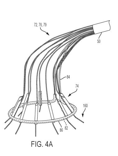
[0022] FIG. 4A depicts a first embodiment for confirming the position of
the anchor
launchers with position-revealing protrusions disposed in a relaxed state.
[0023] FIG. 4B depicts the FIG. 4A embodiment with the position-revealing
protrusions disposed in a deflected state.
[0024] FIG. 4C depicts a detail of the FIG. 4A embodiment.
[0025] FIG. 4D depicts a detail of FIG. 4C.
[0026] FIG. 5A depicts an alternative embodiment for implementing
position-
revealing protrusions that protrude from the anchor launchers, with the
position-revealing
protrusions in a relaxed state.
[0027] FIG. 5B depicts the FIG. 5A embodiment with the position-revealing
protrusions disposed in a deflected state.
[0028] FIG. 5C is a cut-away detail of the FIG. 5A embodiment when the
anchor has
not yet been launched out of the anchor launcher.
[0029] FIG. 5D is a detail of the FIG. 5A embodiment after the anchor has
been
launched.
DESCRIPTION OF THE PREFERRED EMBODIMENTS
[0030] This application describes methods and apparatuses for delivering
and
installing a constricting cord or an annulus ring into a cardiac valve
annulus. In the
constricting cord embodiments, a cord with an open distal loop is installed
into a cardiac
valve annulus using the apparatuses and/or methods described herein, and after
waiting for
tissue ingrowth to occur, the cord can be constricted in order to reduce the
diameter of the
annulus. These embodiments are useful for correcting or improving a variety of
valve-related
conditions (including but not limited to mitral valve regurgitation). In the
annulus ring
CA 03042021 2019-04-26
WO 2018/080965
PCT/US2017/057811
6
embodiments, an annulus ring (i.e., a closed loop of cord) is installed into a
cardiac valve
annulus to either (a) stabilize the shape of the annulus and prevent the
annulus from
expanding or (b) serve as the foundation onto which a replacement valve can be
mounted.
These embodiments are useful in the contexts of reducing valve regurgitation
and cardiac
valve replacement.
[0031] FIGS. 1A, 1B, 2A, and 2B are views of an apparatus 25 for
delivering and
installing a cord onto a cardiac valve annulus, such as the mitral valve
annulus or the
tricuspid valve annulus. In all four of these figures, the housing 40 is
disposed on the
proximal side of the apparatus 25, and an outer sleeve 60 is disposed at the
distal side of the
apparatus. More specifically, FIGS. lA and 1B are left and right side views,
respectively, of
the apparatus 25 as it appears when the outer sleeve 60 of the apparatus is in
an extended
position; and FIGS. 2A and 2B are left and right side views, respectively, of
the same
apparatus 25 as it appears when the outer sleeve 60 is in a retracted
position. When the outer
sleeve 60 is retracted (as shown in FIGS. 2A and 2B), the distal assembly 70
(which includes
the distal loop portion of the cord) extends out past the distal end of the
outer sleeve 60.
When the outer sleeve 60 is extended (as shown in FIGS. lA and 1B), the distal
assembly is
collapsed and is disposed within the outer sleeve 60, and is therefore not
visible in those
figures. The extension and retraction of the outer sleeve 60 with respect to
the core 50 is
controlled by the sleeve retractor 44.
[0032] FIG. 3A is a detailed view of a distal assembly 70 that has
emerged from
within the outer sleeve 60 as a result of the retraction of the outer sleeve
60, so that the distal
assembly 70 extends distally beyond the distal end of the outer sleeve 60. The
distal assembly
70 in the illustrated embodiment includes ten anchor launchers 74, each of
which is supported
by its own individual support arm 72. But in alternative embodiments, a
different number of
support arms 72 and anchor launchers 74 may be used (e.g., between 4 and 16
support arms
and between 4 and 16 anchor launchers).
[0033] The at least four support arms 72 are mounted to the core 50. The
support
arms 72 extend distally beyond the distal end of the core. Suitable materials
for forming the
support arms 72 include stainless steel, nitinol, and other biocompatible
metals. The support
arms are flexible enough to collapse within the outer sleeve 60 (as seen in
FIG. 1), but spring
back to their original shape when extended distally beyond the confines of the
outer sleeve 60
(as seen in FIGS. 2 and 3A).
CA 03042021 2019-04-26
WO 2018/080965
PCT/US2017/057811
7
[0034] At least four anchor launchers 74 are supported by respective ones
of the at
least four support arms 72. Each of the anchor launchers has a distal end.
Suitable designs for
the anchor launchers and the anchors contained therein can be found in US
application
14/895,711 (US2016/0120645) and US patent 9,517,130, each of which is
incorporated
herein by reference. An anchor is disposed in each of the anchor launchers 74.
Each of the
anchor launchers 74 is has a pull-wire trigger, and each of the pull wires 76
is operatively
connected to one of the anchor launchers 74 so that pulling on a respective
pull wire will
launch the respective anchor out of the distal end of the anchor launcher 74
so that the
respective anchor becomes embedded in the annulus or the tissue adjacent to
the annulus.
[0035] When the outer sleeve 60 is in the extended position (as it is in
FIG. 1), the
support arms 72 and the anchor launchers 74 are all disposed within the outer
sleeve 60, and
the support arms 72 are collapsed to fit inside the outer sleeve 60. But when
the outer sleeve
60 is in the retracted position (as it is in FIGS. 2 and 3A), the anchor
launchers 74 and at least
a portion of the support arms 72 extend distally beyond the distal end of the
outer sleeve 60.
The support arms are shaped such that when the outer sleeve 60 is in the
retracted position,
the support arms 72 hold the distal ends of the anchor launchers 74 at
positions that
correspond to a shape of the annulus, with the distal ends of the anchor
launchers 74
distributed about a perimeter of the shape of the annulus.
[0036] A constricting cord has a distal loop portion 82, a first proximal
portion 84,
and a second proximal portion 84. The distal loop portion 82 of the cord is
preferably
surrounded by a sleeve 86 of material that promotes tissue ingrowth. The
sleeve 86 is
preferably soft and flexible. Suitable materials include fabric braids (e.g.,
made of
polyethylene terephthalate (PET) fabric. Preferably, all three portions of the
constricting cord
(i.e., the distal loop portion 82, the first proximal portion 84, and the
second proximal portion
84 are all regions of a single continuous cord). Examples of suitable
materials for the
constricting cord include ultra-high-molecular-weight polyethylene (e.g.,
Dyneemag) and
other strong and flexible materials.
[0037] Each of the anchor launchers 74 houses and anchor (75, shown in
FIGS. 3B
and 3C). These anchors are distributed about the distal loop portion 82 of the
cord and
connected to the distal loop portion 82 of the cord, and each of the anchors
is configured to
anchor a respective region of the distal loop portion 82 of the cord to the
annulus or to tissue
adjacent to the annulus. In some embodiments, the connection between the
anchors 75 and
CA 03042021 2019-04-26
WO 2018/080965
PCT/US2017/057811
8
the distal loop portion 82 of the cord is implemented by running the distal
loop portion 82 of
the cord through a slot in each of the anchors. In alternative embodiments,
this connection is
implemented by connecting the anchors to the sleeve 86 that surrounds the
distal loop portion
82 of the cord, or to one or more different intervening members (not shown)
that link each of
the anchor 75 to the distal portion 82 of the cord.
[0038] Note that the shape of the distal loop portion 82 of the cord in
FIG. 3A is
round, and this shape is suitable when the cord is installed onto a round
annulus. In
alternative embodiments, when the cord is installed onto an annulus with a
different shape
(e.g., a mitral valve annulus that is D-shaped), the support arms 72 are pre-
shaped so that the
distal ends of the anchor launchers 74 will be distributed about the perimeter
of that
differently-shaped annulus prior to implantation. This will result in a D-
shaped distal loop
portion 82 subsequent to implantation.
[0039] Preferably, the shape and size of the support arms 72 are designed
to fit the
anatomy of the individual patient, so that when the outer sleeve 60 is
retracted, the distal loop
portion 82 of the cord will be opened by the support arms 72 and spread around
the annulus,
so that it will be in the correct location ready for the anchors to be
launched with little
adjustment. This may be achieved by designing the 3D shape of the support arms
72 so that
they each extend in a predefined angulation from the core 50. When a cord is
being installed
on the tricuspid valve annulus, the support arms 72 are preferably shaped so
that none of the
anchor launchers 74 will be positioned on or adjacent to the AV node to
prevent potential
damage to that node.
[0040] FIG. 3A also depicts a set of sleeves 79, 89. As explained above,
each of the
anchor launchers 74 is supported by one of the support arms 72 and is actuated
by one of the
pull wires 76. To facilitate smoother opening of the support arms 72 into the
configuration
depicted in FIG. 3A, it is preferable to surround the support arm 72 and the
pull wire 76 that
terminate at each individual anchor launcher 74 in a sleeve 79. In this
embodiment, there will
be one sleeve 79 for each of the anchor launchers 74, and the support arms 72
and the pull
wires 76 for that anchor launcher 74 will run through the center of the
corresponding sleeve
79 In some embodiments, these sleeves 79 are made from clear shrink tubing
with an inner
diameter (after shrinking) that is large enough so as not to interfere with
the slidability of the
pull wires 76 within the sleeves 79. In alternative embodiments, the sleeves
79 may be made
from other polymer materials with a similar inner diameter.
CA 03042021 2019-04-26
WO 2018/080965
PCT/US2017/057811
9
[0041] Optionally, an additional sleeve 89 is provided, and the proximal
portions 84
of the cord run through this additional sleeve 89. The sleeve 89 is similar to
the sleeve 79
discussed above, and is dimensioned to have an inner diameter that is large
enough so as not
to interfere with the slidability of the proximal portions 84 of the cord
within the sleeve 89.
[0042] The distal ends of the anchor launchers 74 are pressed against the
annulus and,
after proper positioning has been confirmed (e.g. using fluoroscopy and echo
imaging), the
anchor launchers 74 are triggered by pulling on the proximal ends of the pull
wires 76. This
causes each of the anchor launchers 74 to launch its anchor into the annulus.
Preferably, all of
the anchors launchers 74 are triggered simultaneously.
[0043] FIGS. 3B and 3C illustrate an example of one way to implement the
anchor
launchers 74. Each anchor launcher 74 includes a housing 74h that has an open
front end. The
housing 74h has a cylindrical interior void. An anchor 75 is disposed in the
front section of
the void in the housing, and an anchor launching spring 74s is disposed in the
rear portion of
the void in the housing 74h in a compressed state. The spring 74s is
preferably a coil spring.
In the illustrated embodiment, the back end (i.e., the proximal end) of the
spring 74s is
retained in housing 74h by a spring retention loop or hook 74r.
[0044] Each anchor launcher 74 includes an actuator configured to prevent
the spring
from expanding from the compressed state prior to being actuated, and to
permit the spring to
expand from the compressed state upon being actuated. In the illustrated
embodiment, the
actuator is implemented using a pull wire 76 that initially passes coaxially
through the anchor
launching spring 74s.
[0045] In the initial state (i.e., prior to actuation) depicted in FIG.
3B, the distal
portion of the pull wire 76 passes through and interfaces with an opening 74p
in the sidewall
of the housing 74h The front end (i.e., the distal end) of the spring 74s
presses against the
back end of the anchor 75. In the illustrated embodiment, the back end of the
anchor is a ring-
shaped section 75r. Prior to actuation, the pull wire 76 passes through the
notch 75n in the
ring 75r at the back of the anchor 75 and also passes through the opening 74p
of the housing
74h. The presence of the distal portion of the pull wire 76 in this position,
engaged with the
opening 74p, prevents the spring 74s from expanding, thereby keeping the
spring 74s in a
compressed state.
CA 03042021 2019-04-26
WO 2018/080965
PCT/US2017/057811
[0046] When the pull wire 76 is pulled in a proximal direction, the
distal portion of
pull wire 76 is pulled inwardly through the opening 74p and is withdrawn from
the opening
74p. At this point, the spring 74s will expand into the front section of the
housing 74h and
push the anchor 75 forward such that the anchor 75 exits the front end of
housing, as depicted
in FIG. 3C. The spring 74s pushes the anchor 75 with sufficient force to
implant the anchor
into the annulus or into tissue adjacent to the annulus. It is preferable to
pull the wire 76 in
the proximal direction with a jerk (i.e., with rapid acceleration), because it
makes the
launching more reliable and prevents the anchor launcher 74 from lifting away
from the
surface of the target tissue prior to implantation.
[0047] FIG. 4A depicts a first embodiment for confirming that the distal
ends of the
anchor launchers 74 are pressed against the annulus before the anchor
launchers 74 are
triggered. This embodiment operates in the same way as the FIG. 3A-C
embodiment
described above and includes the various components described in connection
with those
figures, except that the FIG. 4A embodiment includes one additional set of
elements ¨ the
flexible radio-opaque protrusions 160. Note that the same reference numbers
are used in FIG.
3A-C and FIGS 4A-4D to denote corresponding elements.
[0048] In this FIG. 4A embodiment, the flexible radio-opaque protrusions
160 are
attached to the anchor launchers 74 so that in their initial relaxed state,
the protrusions 160
protrude distally beyond the distal end of the anchor launchers 74. In some
embodiments, the
protrusions 160 extend between 4 and 10 mm beyond the distal end of the anchor
launchers
74. In some embodiments, the diameter of the protrusions 160 is between 0.05
and 0.3 mm.
In some embodiments, the protrusions 160 are preferably bent radially outward
at a small
angle (e.g., 5-20 ) with respect to an axis defined by each anchor launcher
74. In alternative
embodiments (not shown) the protrusions 160 are parallel to the axis defined
by each anchor
launcher 74.
[0049] Each of the protrusions 160 is arranged with respect to a
respective anchor
launcher 74 so that the protrusion 160 is free to move from a relaxed state to
a deflected state.
The protrusions 160 preferably have sufficient flexibility such that
progressive advancement
of the respective anchor launcher in a distal direction beyond a point at
which the protrusion
makes contact with the annulus or the tissue adjacent to the annulus results
in progressive
deflection (or bending) of the protrusion as the distal end of the anchor
launcher 74 is pushed
towards the annulus. In the FIG 4A/13 embodiment, each of the protrusions 160
will be
CA 03042021 2019-04-26
WO 2018/080965
PCT/US2017/057811
11
progressively deflected or bent further outward until it reaches the flattened
configuration
depicted in FIG. 4B. In the flattened configuration, the protrusions 160 will
be deflected or
bent radially outward at a much larger angle (e.g., 70-90 ) as depicted in FIG
4B In
alternative embodiments (not shown), the protrusions will deflect or bend
radially inward
instead of outward at a similar larger angle. Note that as the flexible radio-
opaque protrusions
160 are progressively moved closer and closer to the annulus, the angle of
deflection or
bending of the protrusions 160 with respect to the axis defined by each anchor
launcher 74
will progressively increase until it reaches the maximum angle.
[0050] The angles of each of the protrusions 160 with respect to an axis
defined by
each anchor launcher 74 can be visualized from outside the subject body using
fluoroscopy to
determine if the distal end of each of the anchor launchers 74 has made
contact with the
annulus. Note that the anchor launchers 74 themselves are preferably made of
metal such as
stainless steel that can be visualized using fluoroscopy. If it appears that
any of the
protrusions 160 has not been fully deflected or bent into its flattened
configuration (which
indicates that the distal end of the anchor launcher 74 is not sufficiently
close to the annulus
or to tissue adjacent to the annulus), the entire distal assembly 70 can be
repositioned by
manipulating the controls back at the proximal end of the device until all of
the protrusions
160 have been moved into their flattened configuration. After all of the
protrusions 160 are
positioned in their flattened configuration (which indicates that the distal
end of each of the
anchor launchers 74 is contacting the annulus), the anchor launchers 74 are
triggered.
[0051] Suitable materials for making the radio-opaque protrusions 160
include wires
made from radio-opaque alloys (e.g. 80% platinum and 20% iridium, gold alloys,
and
platinum alloys), or other alternatives that will be apparent to persons
skilled in the relevant
arts. The protrusions 160 should be flexible enough to deflect or bend when
they are pressed
against the annulus by manipulation of the catheter body or the controls
disposed on the
proximal side of the apparatus 25 (shown in FIGS. 1-2). Whenever a protrusion
160 that has
been pressed against the annulus is pulled back into a position at which it no
longer presses
against the annulus or the tissue adjacent to the annulus, the protrusion 160
preferably springs
back towards it original relaxed state.
[0052] FIG. 4C depicts a detail of the FIG. 4A embodiment when the
flexible radio-
opaque protrusions 160 are disposed in their original small-angle
configuration (i.e., the
original relaxed state). FIG. 4D depicts one approach for affixing the
protrusions 160 to the
CA 03042021 2019-04-26
WO 2018/080965
PCT/US2017/057811
12
anchor launchers 74 using a plurality of welding points 164. A wide variety of
alternative
approaches for attaching the protrusions 160 to the anchor launchers 74 can be
readily
envisioned, including but not limited to adhesives and fasteners
[0053] FIGS. 5A-5D depicts an alternative embodiment for implementing
flexible
radio-opaque protrusions 160' that protrude from anchor launchers 74. These
flexible radio-
opaque protrusions 160' are similar to the corresponding protrusions 160 in
the FIG. 4
embodiment, except that in the FIG. 5 embodiment, instead of welding the
protrusions 160'
to the anchor launchers 74, the protrusions 160' are connected to the pull
wires 76 that are
used for triggering the anchor launcher 74. One suitable approach for making
the connection
between the protrusions 160' and the pull wires 76 is to crimp those two
components together
using a crimped tube 166. Alternative approaches for making that connection
include
adhesives, knots, etc. and will be apparent to persons skilled in the relevant
arts. FIG. 5A
depicts this embodiment with the protrusions 160' in the relaxed/extended
state, and FIG. 5B
depicts this embodiment with the protrusions 160' in the deflected/flattened
state.
[0054] FIG. 5C is a cut-away detail of the FIG. 5A embodiment showing
that when
the anchor 75 has not yet been launched out of the anchor launchers 74, the
flexible radio-
opaque protrusions 160' pass through the center of the anchor 75 before
passing distally
beyond the distal end of the anchor launcher 74. And FIG. 5D is a detail of
the FIG. 5A
embodiment showing that after the anchor 75 has been launched out of the
anchor launchers
74, both the pull wire 76 and the protrusions 160' are withdrawn in a proximal
direction 168.
[0055] Any of the embodiments described above in connection with FIGS. 4-
5 may
be used to implement a method for affixing a cord to an annulus. This method
includes
positioning, in a vicinity of the annulus, (a) a cord 82 having a distal loop
portion, (b) at least
four anchors 75 distributed about the cord, wherein each of the at least four
anchors 75 is
configured to anchor a respective region of the cord 82 to the annulus or to
tissue adjacent to
the annulus, (c) at least four anchor launchers 74, each of the anchor
launchers having a distal
end, wherein each of the anchor launchers 74 is configured to launch a
respective one of the
at least four anchors 75 out of the anchor launcher's distal end so that the
respective anchor
becomes embedded in the annulus or the tissue adjacent to the annulus, and (d)
at least four
flexible radio-opaque protrusions 160, each of the protrusions is arranged
with respect to a
respective one of the at least four anchor launchers 74 so that the protrusion
160 is free to
move from a relaxed state to a deflected state, wherein in the relaxed state
the protrusion
CA 03042021 2019-04-26
WO 2018/080965
PCT/US2017/057811
13
protrudes distally beyond the distal end of the respective anchor launcher 74,
and wherein
each of the protrusions 160 is shaped and arranged so that progressive
advancement of the
respective anchor launcher 74 in a distal direction beyond a point at which
the protrusion 160
makes contact with the annulus or the tissue adjacent to the annulus results
in progressive
deflection of the protrusion 160.
[0056] This method also includes adjusting a position of the anchor
launchers 74 until
fluoroscopic images of the protrusions 160 indicate that each of the
protrusions is deflected
beyond a threshold angle; and triggering each of the anchor launchers 74 to
launch a
respective anchor 75 at a time when fluoroscopic images of the protrusions 160
indicate that
each of the protrusions is deflected beyond the threshold angle. The value of
the threshold
angle that indicates that the distal end of each anchor launcher 74 is
sufficiently close to the
annulus (or the tissue adjacent to the annulus) will depend on the geometry of
the protrusion
160 with respect to the anchor launcher 74. In some embodiments, the threshold
angle will
correspond to at least 15 of additional deflection above and beyond the
bending angle that
corresponds to the initial relaxed state (e.g., above and beyond the initial
angle of 5-20 for
the FIG 4A embodiment).
[0057] Preferably, each of the protrusions 160 that is used in connection
with
implementing this method is arranged so that when a protrusion 160 in the
deflected state is
moved to a position at which the protrusion is no longer being pressed against
the annulus or
the tissue adjacent to the annulus, the protrusion returns towards the relaxed
state.
[0058] The embodiments described above in connection with FIGS. 4-5 rely
on tissue
ingrowth to strengthen the bond between the distal loop portion 82 of the cord
and the
annulus. In these embodiments, the distal loop portion 82 of the cord is
attached to the
annulus by anchoring the sleeve 86 (through which the distal loop portion 82
runs) to the
annulus using the anchors 75. Immediately after implantation, the bond between
the distal
loop portion 82 the annulus is typically not strong enough to withstand
constricting. But
because the sleeve 86 is made of material that accepts tissue ingrowth,
ingrowth of tissue at
the annulus into the sleeve 86 will begin to occur after implantation. This
tissue ingrowth will
eventually (e.g. over the course of 2-12 weeks) strengthen the bond between
the sleeve 86
and the annulus until the bond is strong enough to withstand constricting.
CA 03042021 2019-04-26
WO 2018/080965
PCT/US2017/057811
14
[0059] In alternative embodiments, the constricting cord 82 with an open
distal loop
shown in FIGS. 4A-4C is replaced with an annulus ring (not shown), which is a
closed loop
of cord. In these embodiments, instead of implanting the distal loop portion
82 of a cord into
the annulus so that the proximal portions 84 of the cord extend backwards into
the core 50 (as
described above), a closed loop of cord is implanted into the annulus or into
tissue adjacent to
the annulus. Preferably, the closed loop of cord is surrounded by a sleeve in
a manner similar
to the way that the distal loop portion 82 of the cord was enclosed in a
sleeve 86 in the FIGS.
4A-4C embodiment.
[0060] The concepts described herein are not limited to the context of
installing rings
or constricting cords to cardiac valve annuli, and may be extended to other
situations
including but not limited to an annulus in a subject's gastrointestinal tract.
For example, a
device may be aligned with a target location using the following method.
[0061] First, at least three flexible radio-opaque protrusions are
arranged with respect
to the device so that each of the protrusions is free to move from a relaxed
state to a deflected
state, wherein in the relaxed state the protrusion protrudes distally beyond
the device. Each of
the protrusions is shaped and arranged so that progressive advancement of the
device in a
distal direction beyond a point at which the protrusion makes contact with a
structure in the
target location results in progressive deflection of the protrusion. And each
of the protrusions
is arranged so that when a protrusion in the deflected state is moved to a
position at which the
protrusion is no longer being pressed against the structure, the protrusion
returns towards the
relaxed state.
[0062] The device is then positioned in a vicinity of the target
location. The position
of the device is then adjusted until fluoroscopic images of the protrusions
indicate that each
of the protrusions is deflected beyond a threshold angle. Finally, the device
is released at a
time when fluoroscopic images of the protrusions indicate that each of the
protrusions is
deflected beyond the threshold angle. Depending on the nature of the device,
the device may
be anchored in place at the time when fluoroscopic images of the protrusions
indicate that
each of the protrusions is deflected beyond the threshold angle.
[0063] While the present invention has been disclosed with reference to
certain
embodiments, numerous modifications, alterations, and changes to the described
embodiments are possible without departing from the sphere and scope of the
present
CA 03042021 2019-04-26
WO 2018/080965
PCT/US2017/057811
invention, as defined in the appended claims. Accordingly, it is intended that
the present
invention not be limited to the described embodiments, but that it has the
full scope defined
by the language of the following claims, and equivalents thereof.