Note: Descriptions are shown in the official language in which they were submitted.
MOBILE PUMP SYSTEM
[0001] (This paragraph is intentionally left blank.)
BACKGROUND
Field
[0002] The present disclosure relates to a mobile pump system and a method for
performing a
pressure pumping application.
Technical Considerations
[0003] Pressure pumping includes a propagation of fractures through layers of
rock using
pressurized fluid and/or pumping cement into a wellbore to complete it.
[0004] In one non-limiting example of pressure pumping, to extract oil and/or
gas trapped in
formations beneath the Earth's surface, drilling of a wellbore is required,
and the oil and/or gas may
be recovered and extracted through the wellbore. Various pumps may be used
during the drilling
and oil and/or gas recovery process.
[0005] In some non-limiting oilfield applications, drilling may include
forming horizontal laterals
extending out from a vertical section of the wellbore. The formation defining
the vertical or lateral
section may be fractured in sections, such that a fracture stimulation
treatment is completed in the
first section before moving on to apply a fracture stimulation treatment on a
second section. This
may be performed using a plug-and-perf technique in which a perforating gun is
used to initiate
fractures in the formation in the section after a plug is positioned between
the first section and the
second section. The plug seals the first section of the lateral from the other
sections. This plug-and-
perf technique is repeated for each section of the lateral until all intended
sections of the lateral are
perforated and fracture stimulated.
[0006] The plug may be positioned at a predetermined location along the
lateral by utilizing a
pump system to pump a fluid into the wellbore, which exerts a pressure on the
plug. The pressure
on the plug moves the plug along the lateral to the desired position.
Positioning the plug using the
pump is considered an ancillary application, commonly referred to as
"pumpdown".
1
Date Recue/Date Received 2020-12-29
[0007] Existing pumps used in pressure pumping application, such as in
ancillary pumpdown
applications have numerous drawbacks. For example, existing pumps use an
internal combustion
engine driven by diesel fuel, which have high carbon footprints. In addition,
these existing pumps
are cumbersome and require considerable room at the well site. Further, these
existing pumps do
not allow for sufficiently precise control of flow rate, making it difficult
to move the plug to the
desired position. Existing pumps are expensive to acquire and maintain, and
they create significant
noise at a decibel level that is known to harm human hearing without adequate
ear protection.
[0008] Further, existing pumping systems utilized in pressure pumping
applications, including
ancillary pressure pumping applications, are not capable of sufficiently low
flow rates or precise
control of the flow rate. The existing pump systems lack precise control and
the ability to operate at
lower flow rates because they utilize conventional transmissions that are
incapable of smooth
increase or decrease in pumping rates. This may be the result of hesitation
and slugging common
when primary gears disengage and engage the secondary shaft. As a result,
existing pressure
pumping systems do not effectively remedy screen outs occurring during
hydraulic fracturing
applications.
[0009] Therefore, a pump suitable for pressure pumping applications that
overcomes some or all
of the disadvantages of existing pumps is desired.
SUMMARY
[0010] The present disclosure is directed to a mobile pump system including: a
trailer movable
by a vehicle; and a pump mounted to the trailer, the pump configured to pump a
fluid. The pump
includes an electrically-driven motor mounted to the trailer or is turbine
powered by a turbine
mounted to the trailer.
100111 The pump may be configured to pump the fluid into a wellbore at a tie-
in point upstream
of a wellhead of the wellbore. The fluid may include water and/or a chemical
additive. The pump
may include an auger or impeller configured to move the fluid. The pump may
not be permanently
installed at a site for performing a pressure pumping application. The
electrically-driven motor may
be fueled by a battery, natural gas, diesel fuel, or gasoline. The pump may be
configured to adjust a
flow rate of the pump by 1/10th of a bpm. The pump may be in fluid
communication with a wellbore.
The turbine may be operated using field gas. The mobile pump system may
include plurality of
pumps mounted to the trailer, where each pump may include an electrically-
driven motor mounted
to the trailer or may be turbine powered by a turbine mounted on the trailer.
The mobile pump system
2
CA 3042189 2019-05-03
may include controller configured to remotely control the pump. The controller
may include a
portable computing device. The pump may be configured to pump the fluid at a
flow rate as low as
0.1 bpm. The turbine may include a direct coupled gear connection.
[0012] The present disclosure is also directed to a method for performing a
pressure pumping
application including: providing a mobile pump system including: a trailer
movable by a vehicle;
and a pump mounted to the trailer, the pump configured to pump a fluid, where
the pump includes
an electrically-driven motor mounted to the trailer or is turbine powered by a
turbine mounted to the
trailer.
[0013] The method may include pumping the fluid from a fluid container into a
wellbore using
the pump to move the fluid from the fluid container into the wellbore. The
method may include
positioning a plug in a lateral of the wellbore using the fluid pumped into
the wellbore. The pump
may be configured to pump the fluid into the wellbore at a tie-in point
upstream of a wellhead of the
wellbore. The fluid may include water and/or a chemical additive. The pump may
include an auger
or impeller configured to move the fluid. The pump may not be permanently
installed at a site for
performing a pressure pumping application. The electrically-driven motor may
be fueled by a
battery, natural gas, diesel fuel, or gasoline. The pump may be configured to
adjust a flow rate by
1/10th of a bpm. The pump may be in fluid communication with a wellbore. The
turbine may be
operated using field gas. The pump may be configured to pump the fluid at a
flow rate as low as 0.1
bpm. The pump may be remotely controlled by a controller. The controller may
include a portable
computing device. The pump may be configured to pump the fluid at a flow rate
of up to 140 barrels
per minute (bpm) at a pressure of up to 20,000 psi.
[0014] Further embodiments are set forth in the following numbered clauses:
[0015] Clause 1: A mobile pump system comprising: a trailer movable by a
vehicle; and a pump
mounted to the trailer, the pump configured to pump a fluid, wherein the pump
comprises an
electrically-driven motor mounted to the trailer or is turbine powered by a
turbine mounted to the
trailer.
[0016] Clause 2: The mobile pump system of clause 1, wherein the pump is
configured to pump
the fluid into a wellbore at a tie-in point upstream of a wellhead of the
wellbore.
[0017] Clause 3: The mobile pump system of clause 1 or 2, wherein the fluid
comprises water
and/or a chemical additive.
[0018] Clause 4: The mobile pump system of any of clauses 1-3, wherein the
pump comprises an
auger or impeller configured to move the fluid.
3
CA 3042189 2019-05-03
[0019] Clause 5: The mobile pump system of any of clauses 1-4, wherein the
pump is not
permanently installed at a site for performing a pressure pumping application.
[0020] Clause 6: The mobile pump system of any of clauses 1-5, wherein the
electrically-driven
motor is fueled by a battery, natural gas, diesel fuel, or gasoline.
[0021] Clause 7: The mobile pump system of any of clauses 2-6, wherein the
pump is configured
to adjust a flow rate of the pump by 1/10th of a bpm.
[0022] Clause 8: The mobile pump system of any of clauses 1-7, wherein the
pump is in fluid
communication with a wellbore.
[0023] Clause 9: The mobile pump system of any of clauses 1-8, wherein the
turbine is operated
using field gas.
[0024] Clause 10: The mobile pump system of any of clauses 1-9, comprising a
plurality of pumps
mounted to the trailer, wherein each pump comprises an electrically-driven
motor mounted to the
trailer or is turbine powered by a turbine mounted on the trailer.
[0025] Clause 11: The mobile pump system of any of clauses 1-10, further
comprising a controller
configured to remotely control the pump.
[0026] Clause 12: The mobile pump system of clause 11, wherein the controller
comprises a
portable computing device.
[0027] Clause 13: The mobile pump system of any of clauses 1-12, wherein the
pump is
configured to pump the fluid at a flow rate as low as 0.1 bpm.
[0028] Clause 14: The mobile pump system of any of clauses 1-13, wherein the
turbine comprises
a direct coupled gear connection.
[0029] Clause 15: The mobile pump system of any of clauses 1-14, wherein the
pump is
configured to pump the fluid at a flow rate of up to 140 barrels per minute
(bpm) at a pressure of up
to 20,000 psi.
[0030] Clause 16: A
method for performing a pressure pumping application comprising:
providing a mobile pump system comprising: a trailer movable by a vehicle; and
a pump mounted
to the trailer, the pump configured to pump a fluid, wherein the pump
comprises an electrically-
driven motor mounted to the trailer or is turbine powered by a turbine mounted
to the trailer.
[0031] Clause 17: The method of clause 16, further comprising: pumping the
fluid from a fluid
container into a wellbore using the pump to move the fluid from the fluid
container into the wellbore.
[0032] Clause 18: The method of clause 17, further comprising: positioning a
plug in a lateral of
the wellbore using the fluid pumped into the wellbore.
4
CA 3042189 2019-05-03
[0033] Clause 19: The method of any of clauses 16-18, wherein the pump is
configured to pump
the fluid into the wellborc at a tie-in point upstream of a wellhead of the
wellbore.
[0034] Clause 20: The method of any of clauses 16-19, wherein the fluid
comprises water and/or
a chemical additive.
[0035] Clause 21: The method of any of clauses 16-20, wherein the pump
comprises an auger or
impeller configured to move the fluid.
[00361 Clause 22: The method of any of clauses 16-21, wherein the pump is not
permanently
installed at a site for performing a pressure pumping application.
[0037] Clause 23: The method of any of clauses 16-22, wherein the electrically-
driven motor is
fueled by a battery, natural gas, diesel fuel, or gasoline.
[0038] Clause 24: The method of any of clauses 16-23, wherein the pump is
configured to adjust
a flow rate by 1/10th of a bpm.
[0039] Clause 25: The method of any of clauses 16-24, wherein the pump is in
fluid
communication with a wellbore.
[0040] Clause 26: The method of any of clauses 16-25, wherein the turbine is
operated using field
gas.
[0041] Clause 27: The method of any of clauses 16-26, wherein the pump is
configured to pump
the fluid at a flow rate as low as 0.1 bpm.
[0042] Clause 28: The method of any of clauses 16-27, wherein the pump is
remotely controlled
by a controller.
[0043] Clause 29: The method of clause 28, wherein the controller comprises a
portable
computing device.
[0044] Clause 30: The method of any of clauses 16-29, wherein the pump is
configured to pump
the fluid at a flow rate of up to 140 barrels per minute (bpm) at a pressure
of up to 20,000 psi.
BRIEF DESCRIPTION OF THE DRAWINGS
[0045] Additional advantages and details are explained in greater detail below
with reference to
the exemplary embodiments that are illustrated in the accompanying schematic
figures, in which:
[0046] FIG. 1 shows a schematic cross-sectional view of the Earth at an oil
and/or gas production
site utilizing horizontal drilling techniques;
CA 3042189 2019-05-03
[0047] FIG. 2 shows another schematic cross-sectional view of the Earth at an
oil and/or gas
production site utilizing horizontal drilling techniques and a mobile pump
system;
[0048] FIG. 3 shows a schematic aerial view of a well pad at an oil and/or gas
production site, the
well pad including a mobile pump system;
[0049] FIG. 4 shows a schematic side view of a mobile pump system according
having a trailer
and a cab for moving the mobile pump system;
[0050] FIG. 5 shows a schematic top view of a mobile pump system including the
trailer and the
electrically-driven pump or turbine-driven pump
[0051] FIG. 6 shows a schematic side view of an auger-style pump of a mobile
pump system;
[0052] FIG. 7 shows a controller for controlling a mobile pump system; and
[0053] FIG. 8 shows a schematic top view of a mobile pump system including a
pump driven by
an electric motor;
[0054] FIG. 9 shows a schematic perspective view of a mobile pump system
including a pump
driven by a turbine;
[0055] FIG. 10 shows a schematic perspective view of a mobile pump system
including a pump
driven by a turbine, with the trailer including a fuel tank; and
[0056] FIG. 11 shows a schematic top view of a mobile pump system including a
secondary pump.
DETAILED DESCRIPTION
[0057] For purposes of the description hereinafter, the terms "end," "upper,"
"lower," "right,"
"left," "vertical," "horizontal," "top," "bottom," "lateral," "longitudinal,"
and derivatives thereof
shall relate to the invention as it is oriented in the drawing figures.
However, it is to be understood
that the invention may assume various alternative variations and step
sequences, except where
expressly specified to the contrary. It is also to be understood that the
specific devices and processes
illustrated in the attached drawings, and described in the following
specification, are simply
exemplary embodiments or aspects of the invention. Hence, specific dimensions
and other physical
characteristics related to the embodiments or aspects disclosed herein are not
to be considered as
limiting.
[0058] The present disclosure is directed to a mobile pump system that
includes: a trailer movable
by a vehicle; and a pump mounted to the trailer, the pump configured to pump a
fluid, wherein the
pump comprises an electrically-driven motor mounted to the trailer or is
turbine powered by a turbine
6
CA 3042189 2019-05-03
mounted to the trailer. The mobile pump system described herein may be
suitable for pressure
pumping applications.
[0059] Referring to FIG. 1, an oil and/or gas production site 10 is shown. At
the production site
10, the surface 11 (Earth's surface) includes wellbore 12 created by drilling.
The
wellbore 12 includes a wellhead 13, which is a structural component at the
surface 11 of the wellbore
12 which provides a structural and pressure-containing interface for various
drilling and production
equipment. The production site 10 may be a site for conducting hydraulic
fracturing.
[0060] With continued reference to FIG. 1, the production site 10 may utilize
a horizontal drilling
technique in which at least one lateral 14 is used. For the horizontal
drilling technique, the wellbore
12 may include a vertical region of 2,500 to 25,000, such as 6,000 to 15,000
or 6,000 to 10,000 feet
in depth, although the length of this vertical region is not limited to this
range. The wellbore 12 may
include a leveling-off point 16 in which the vertical region ends and the
lateral 14 is drilled
horizontally in the Earth (the lateral 14 may have approximately the same
depth from the surface 11
at all points). Each lateral 14 may have a length of 2,500 ¨ 25,000, such as
3,000 to 10,000 feet, as
measured from the leveling-off point 16 to an end 18 of the lateral 14,
although the length of the
lateral 14 is not limited to this range. It will be appreciated that FIG. 1 is
not drawn to scale, but
merely provides a useful schematic of a production site 10 performing
horizontal drilling.
[0061] The lateral 14 may include a plurality of regions, which are of a
predetermined length.
Hydraulic fracture stimulation treatment may be performed in the lateral 14
individually at each
region. Hydraulic fracture stimulation treatment includes pumping a fracturing
fluid into the
formation. The lateral 14 of the schematic in FIG. 1 includes a first region
20, a second
region 22, a third region 24, a fourth region 26, a fifth region 28, and a
sixth region 30.
[0062] With continued reference to FIG. 1, the production site 10 may utilize
a "plug-and-perr
method for hydraulic fracture stimulation treatment. In FIG. 1, hydraulic
fracture stimulation
treatment has been completed for the first region 20. A fractured first region
32 was created in the
formation at the first region 20. After the hydraulic fracture stimulation
treatment was completed in
the first region 20, a first plug 34 was positioned at an end of the first
region 20 closest to the wellhead 13 (a proximal end of the first region 20).
Once in place, this first
plug 34 may prevent fluid subsequently pumped into the wellbore 12 from
entering the first region
20.
[0063] With continued reference to FIG. 1, hydraulic fracture stimulation
treatment in the second
region 22 of the formation may be initiated by lowering a perforating gun 36
(hereinafter "perf gun")
7
CA 3042189 2019-05-03
into the wellbore 12 and positioning the perf gun 36 in the second region 22.
The perf gun 36 may
be lowered into the wellbore 12 using a perf trailer 37. Once positioned
correctly, charges of the
perf gun 36 may be detonated so as to create multiple connection points from
the wellbore 12 to the
formation in the second region 22. Oil and/or gas may be extracted by escaping
from fractures and
extracted to the surface 11 via the wellbore 12.
[0064] Referring to FIG. 2, the production site 10 is shown at a time after
that depicted in
FIG. 1. The fractured second region 38 is shown, which was created by the perf
gun 36 from FIG.
1. It will be appreciated that FIG. 2 is also not drawn to scale, but merely
provides a useful schematic
of a production site 10 performing horizontal and/or vertical drilling.
[0065] In FIG. 2, a second plug 40 is being lowered into the wellbore 12 by a
plug trailer 41 to be
positioned at a proximal position of the second region 22 (on the end of the
second region 22 closer
to the wellhead 13). The second plug 40 is spaced apart from the first plug 34
by approximately the
length of the second region 22. The second plug 40 may be positioned using
positioning fluid 42 to
provide pressure to the second plug 40 to move the second plug along the
length of the wellbore 12
(including the lateral 14). The positioning fluid 42 may include water and/or
a chemical additive.
The chemical additive may include a friction reducer to reduce surface
tension. The chemical
additive may reduce tension or pipe friction along the wellbore 12 associated
with positioning the
second plug 40.
[0066] The second plug 40 may be positioned using the mobile pump system 44 of
the present
disclosure. The mobile pump system 44 may be used to position the second plug
40 as merely one
non-limiting example of how the mobile pump system 44 may be used in a
pressure pumping
application. However, it will be appreciated that the mobile pump system 44
may be used to
complete other pressure pumping applications using the components of the
mobile pump system 44
described hereinafter.
[0067] The mobile pump system 44 may include a trailer 46 movable by a vehicle
(e.g., a cab
having a fifth wheel). The trailer 46 may be movable by a vehicle, such as a
cab, to and from the
production site 10. In this way, the mobile pump system 44 may be conveniently
moved from
location to location, such as to and from the production site 10, and the
mobile pump system 44 does
not need to be permanently installed at the production site 10. The trailer 46
may be
separable/detachable from the vehicle such that the trailer 46 may be left at
the production site 10
and the vehicle driven away, or the trailer 46 may be integrated with the
vehicle, such that the vehicle
8
CA 3042189 2019-05-03
remains at the production site 10 while the mobile pump system 44 is in use
and drives away after
use of the mobile pump system 44 is completed.
[0068] With continued reference to FIG. 2, the mobile pump system 44 may
further include a
pump 48 mounted to the trailer 46. The pump 48 may be configured to pump the
positioning fluid
42 into the wellbore 12. The pump may include an electric motor 50 mounted to
the trailer 46 or
may be powered by a turbine 50 mounted to the trailer 46. The trailer 46 may
include multiple pumps
48 in some embodiments and may include multiple electric motors or turbines 50
for driving the
pumps 48. As used herein, the term "electric motor" or "electrically-driven
motor" refers to a motor
in which electrical energy is converted into mechanical energy. As used
herein, the term "turbine"
refers to a rotary mechanical device that extracts energy from a fluid (e.g.,
liquid and/or gas) flow
and converts it into useful work to generate electrical energy to power the
pump 48. The trailer 46
may also include a power generator 52 in connection with the pump 48 to fuel
the electrically-driven
motor or the turbine 50 of the pump 48. The power generator 52 may be battery,
natural gas, diesel
fuel, or gasoline fueled. The pump 48 may be driven by the electric motor or
the turbine 50 and not
by an internal combustion engine.
[0069] The pump 48 may be configured to pump the positioning fluid 42, or any
other fluid, at a
flow rate of up to 60 barrels per minute (bpm), such as up to 80 bpm, up to
100 bpm, up to 120 bpm,
up to 140 bpm or higher. A barrel is defined as 42 US gallons, which is
approximately 159 Liters.
The pump 48 may be configured to pump the positioning fluid 42 at far lower
flow rates, and may
pump the positioning fluid 42 at a flow rate as low as 0.1 bpm (when the pump
is not turned off such
that it's flow rate would be 0 bpm). The pump 48 may be controlled such that
its flow rate may be
controlled within 1/10th of a bpm, resulting in a flow rate within 1/10th of a
bpm compared to a
predetermined flow rate. The pump may be configured to adjust the flow rate by
1/10th of a bpin
(e.g., adjust the flow rate of the pump 48 from 60.0 bpm to 59.9 bpm or from
0.2 bpm to 0.1 bpm).
Existing pressure pumping systems, including ancillary pressure pumping
applications, are not
capable of such low flow rates or such precise control of the flow rate. The
existing pump systems
lack precise control and the ability to operate at lower flow rates because
they utilize conventional
transmissions that are incapable of smooth increase or decrease in pumping
rates. This may be the
result of hesitation and slugging common when primary gears disengage and
engage the secondary
shaft.
[0070] The ability to pump at lower rates and to more precisely control the
flow rate of the pump
48 may be especially useful in post-occurrence remedying of "screen outs,"
which are common in
9
CA 3042189 2019-05-03
hydraulic fracturing applications. A screen out occurs when proppant and fluid
(of the positioning
fluid 42, for example) can no longer be injected into the formation. This may
be due to resistant
stresses of the formation becoming too excessive or surface-originated reasons
resulting in loss of
viscosity to carry proppant so that it falls out of suspension and plugs
perforations in the wellbore
12. In this way, the wellbore 12 becomes "packed" with proppant, which does
not allow any further
operations to continue due to high pressures that cannot be overcome from
these blockages.
[0071] In response to screen outs, the wellbore 12 may be opened at the
surface 11 to relieve
pressure and to carry at least some of the proppant out of the wellbore 12 and
create a pathway to
continue fluid injection to clear the wellbore 12 and allow operations to
continue, which is a
dangerous operation. An attempt to continue pumping operations at low rates to
avoid reaching
maximum pressure so that the proppant that is packed is forced through
perforations and into the
wellbore 12 may be attempted. However, due to the limitations of existing
pumps with conventional
engines and transmissions, the pump cannot pump at low enough rates to avoid
again reaching
maximum pressure. As a result, existing systems are often required to switch
to a coiled tubing
procedure to wash the proppant out and carry it back to the surface so that
the wellbore 12 is finally
clear. The
coiled tubing procedure results in shutdown of operations for
3-4 days and is additionally expensive to complete.
[0072] In contrast, existing systems are able to overcome these screen outs
successfully without
reverting to the coiled tubing procedure because the electric motor or the
turbine 50 of the pump 48
allows the pump 48 to inject fluid for displacement at lower rates (as low as
0.1 bpm) over the course
of hours or days without the risks posed by existing systems.
[0073] The ability to pump fluids at lower rates and to more precisely control
the flow rate of the
pump 48 may be especially useful in prevention or mitigation of the adiabatic
effect which can
cause wireline cable melting and/or failure during pump down operations, which
are common in
hydraulic fracturing applications. On pump downs and related jobs involving
wireline operations
with pump assist, the wellhead is equipped with a lubricator and flow tubes to
enable operations in
a wellbore that can have pressure of several thousand pounds or more of
pressure. The process of
bringing the lubricator and the wellbore to the same pressure is known as
"equalization." When the
air in the lubricator compresses faster than it can be evacuated, the
adiabatic compression can cause
the temperature to rise to as much as 1,200 F (-650 C). At high temperatures,
the insulating material
of the cable would melt and the metallurgy of the steel in the cable would
change, causing the actual
wire in the wireline to become brittle and break, even to the point of
severing the wireline within the
CA 3042189 2019-05-03
lubricator. A common name for this condition is "wireline burn up" though
other colloquialisms
and phrases (such as "E-line burn") describe the same condition.
[0074] In practice, to avoid wireline burn-up, the lubricator may first be
filled with fluid prior to
equalizing; this practice can mitigate much of the air and therefore most of
the energy to cause
damage. In order to fill the lubricator with fluid without inducing wireline
burn-up, the fluid must
be introduced at very low rates so that the air can be evacuated at an
equivalent rate so as not to
introduce temperature increases caused by compressing air rapidly. However,
due to the limitations
of existing pump systems with conventional engines and transmissions, the pump
cannot pump at
low enough rates to completely avoid against reaching damaging high
temperatures. In contrast, the
pump 48 would be able to overcome this situation successfully because the
electric motor or the
turbine 50 of the pump 48 allows the pump 48 to inject fluid for displacement
of the air in the
lubricator at lower rates (as low as approximately 0.1 bpm) without the risks
posed by existing
systems.
[0075] The pump 48 may be configured to pump fluid at a pressure of up to
20,000 psi, such as
up to 15,000 psi, up to 12,000 psi, up to 10,000 psi, up to 8,000 psi, or up
to 6,000 psi, although
higher pressures are also contemplated.
[0076] With continued reference to FIG. 2, a fluid tank 54 containing the
positioning fluid 42 may
be in fluid communication with the pump 48. The pump 48 may pump the
positioning
fluid 42 from the fluid tank 54 into the wellbore 12 to position the second
plug 40 at a predetermined
position in the wellbore 12.
[0077] With continued reference to FIG. 2, the mobile pump system 44 may
position the second
plug 40 at a predetermined position in the wellbore 12. The second plug 40 may
be positioned in the
wellbore by providing the previously-described mobile pump system 44. The pump
48 of the mobile
pump system 44 may be placed in fluid communication with the
wellbore 12. The positioning fluid 42 may be pumped from the fluid tank 54
into the
wellbore 12 using the pump 48. The positioning fluid 42 pumped into the
wellbore 12 may exert a
pressure on the second plug 40 so as to move the second plug 40 along the
lateral 14 and into the
predetermined position. The position of the second plug 40 may be monitored
from the surface by
any means known in the art. The flow rate of the positioning fluid 42 pumped
by the pump 48 may
be adjusted and controlled to position the second plug 40. The flow rate may
be increased or
decreased to adjust the rate at which the second plug 40 is moved. For
example, when the second
11
CA 3042189 2019-05-03
plug 40 is proximate the predetermined position, the flow rate of positioning
fluid 42 may be lowered
so that the position of the second plug 40 can be more precisely selected.
[0078] The mobile pump system 44 described herein may be used for any pressure
pumping in
which its characteristics are suitable and is not limited to the above-
described application. For
example, the mobile pump system 44 may be used in hydraulic fracturing
applications. Hydraulic
fracturing applications include any application associated with hydraulic
fracturing performed at a
production site. Hydraulic fracturing refers to fluid injected down the
wellbore through perforations
exceeding the minimum fracture pressure needed to fracture the rock in the
formation. An example
of a hydraulic fracturing application includes ancillary applications
("pumpdown"), such as
positioning a plug (previously described), drillout applications, injecting
acid into the formation,
pressure testing casing, injecting diverter materials, "toe preps" involving
initiating the first fracture
network in a well, and the like. Drillout applications may include
applications performed after the
drilling and fracturing process has concluded and the well is being prepared
to deliver hydrocarbon
production. As one example, a drillout application may include milling or
drilling out plugs
previously positioned in the laterals and removing debris from the milled
plugs by pumping the
debris from the plug location to the surface.
[0079] The mobile pump system 44 allows for the reduction of capital costs
compared to existing
pump systems as the mobile pump system 44 requires less capital costs to build
and operate. The
mobile pump system 44 also significantly reduces repair and maintenance costs
compared to existing
systems. The use of the electric motor or turbine 50 to drive the pump 48
helps to reduce repair and
maintenance costs. The electric motor or turbine 50 has a higher run time
before requiring repairs
compared to conventional internal combustion engines (motors) used in existing
pumps, which are
diesel driven, for example. Keeping the electric motor or turbine 50 cool and
lubricated allows the
electric motor or turbine 50 to have a longer running life compared to the
motors used in existing
systems. The electric motor or turbine 50 also run more efficiently compared
to the motors used in
existing systems, such as in terms of emissions and consumption of fuel.
[0080] The mobile pump system 44 using the electric motor or turbine 50 to
drive the pump 48
also requires significantly less fuel compared to existing systems. The
electric motor or turbine 50
may utilize natural gas powered electric generation, such as the field gas
available at a production
site. Thus, sulfur and other pollutants that arise from diesel combustion in
conventional internal
combustion motors are not present in the combustion of natural gas powered
electric generation. The
inclusion of the electric motor or the turbine 50 in the mobile pump system 44
also reduces the noise
12
CA 3042189 2019-05-03
associated with the mobile pump system 44 as pumps used in existing systems
provide significant
noise pollution and make it difficult to operate such pumps in residential
areas (e.g., near housing
plans, schools, hospitals, and the like).
[0081] The mobile pump system 44 includes a more compact design of the pumps
48 compared
with existing systems. Multiple pumps 48 may be included on the trailer 46.
The more compact
system contributes to a safe production site 10 as there are less components
at the production site 10
to cause a navigational and/or tripping hazard. This compact design also
allows for the mobile pump
system 44 to be set-up faster, resulting in less wasted time and faster time
to production. Moreover,
the mobile pump system 44 may include multiple of at least on component
included in the system,
such as multiple pumps 48, multiple electric motors or turbines 50, multiple
controllers 80, and the
like. The redundancy associated with certain of the components mounted on the
trailer 46 of the
mobile pump system 44 allows the system to avoid stopping operation of the
pressure pumping
application should one of the redundant components fail.
[0082] Referring to FIG. 3, an aerial view of the production site 10 is shown.
The production site
includes a well pad 56. The well pad 56 includes six wellbores 12A-12F, each
wellbore having
a vertical region and at least one lateral traversing a direction different
from the other wellbores of
the well pad 56. In the schematic in FIG. 3, the non-limiting example of a
pressure pumping
application is being conducted at only the first wellbore 12A; however,
multiple well heads may be
in production (e.g., conducting oilfield activity) simultaneously.
[0083] The production site 10 may include at least one fracturing trailer 58A-
58F, each including
at least one fracturing pump 60A-60F. The production site 10 may further
include sand and
fracturing fluid storage tanks 62, which include sand and fracturing fluid
used to keep fractures in
the formation open. The production site 10 may further include a water tank 64
for pumping water
into the first wellbore 12A. The water tank 64 may be in addition to or the
same as the fluid tank 54
containing the positioning fluid 42. The production site 10 may further
include a chemical storage
tank 66, which may store any useful chemical, such as a friction reducer
(e.g., polyacrylamide or a
guar-based chemical). The fracturing pumps 60A-60F may be in fluid
communication with at least
one of the sand and fracturing fluid storage tanks 62, the water tank 64. and
the chemical storage
tank 66 to pump the various materials and/or fluids contained therein into the
first wellbore 12A via
piping 70. The piping 70 may include an isolation valve 72 for isolating the
fracturing pumps 60A-
60F from the first wellbore 12A when the fracturing pumps 60A-60F are not
pumping fluid/material
into the first wellbore 12A.
13
CA 3042189 2019-05-03
[0084] With continued reference to FIG. 3, the production site 10 may further
include a data
monitoring station 68, which may be used to monitor all operations conducted
at the production site
and control those operations accordingly. In some non-limiting examples, the
data monitoring
station 68 may be remote from the production site 10.
[0085] With continued reference to FIG. 3, production site 10 may further
include the mobile
pump system 44A. The production site may include a single mobile pump system
44A or multiple
mobile pump systems 44A-44B, as necessary. In the non-limiting example of FIG.
3, a first mobile
pumping system 44A is used to pump positioning fluid 42 into the first
wellbore 12A. The first
mobile pumping system 44A may include a first trailer 46A, a first power
generator 52A, and a first
pump 48A having a first electric motor 50A. The production site 10 may utilize
a second mobile
pumping system 44B in addition to or in lieu of the first mobile pumping
system 44A. The second
mobile pumping system 44B may include a second trailer 46B, a second power
generator 52B, and
two pumps 48B, 48C, each having an electric motor 50B, 50C. The production
site 10 may include
the fluid tank 54 containing the positioning fluid 42, and the fluid tank 54
may be in fluid
communication with the first pump 48A of the first mobile pumping system 44A.
The first mobile
pumping system 44A and the second mobile pumping system 44B may be moved to
and from the
production site 10 without being permanently installed at the pumping site 10.
[0086] With continued reference to FIG. 3, the first pump 48A may be in fluid
communication
with the first wellbore 12A so as to pump the positioning fluid 42 into the
first wellbore 12A. The
first pump 48A may be in fluid communication with the piping 70 so as to be in
fluid communication
with the first wellbore 12A, and the first pump 48A may intersect with the
piping 70 at a tie-in point 74. The tie-in point 74 may be upstream of the
wellhead of the first
wellbore 12A (e.g., before the piping 70 reaches the wellhead of the first
wellbore 12A).
[0087] Referring to FIG. 4, a non-limiting example of the mobile pump system
44 may include a
cab 76. The cab 76 may be a truck capable of attaching the trailer 46 thereto
(such as via a fifth
wheel), so that the trailer 46 may be hauled to and from the production site
10. The trailer 46 may
be detachable from the cab 76 so that it may be left at the job site, or the
trailer 46 may be an
integrated part of the cab 76 (not detachable therefrom). In some examples,
the cab 76 is the power
generator 52 because the cab may fuel the electric motor or turbine 50 used to
drive the pump 48.
[0088] Referring to FIG. 5, a top view of a non-limiting example of the mobile
pump
system 44 is shown, with the mobile pump system 44 including the trailer 46,
the pump 48 having
the electric motor 50, and the power generator 52. The power generator 52 may
be connected to the
14
CA 3042189 2019-05-03
pump 48 (e.g., the electric motor 50) to fuel the electric motor 50, such that
the electric motor 50
may drive the pump 48.
[0089] Referring to FIG. 6, a non-limiting example of the pump 48 is shown.
The pump 48 may
be any pump suitable for pumping the positioning fluid 42 as previously
described. In one example,
the pump 48 may be an auger-style pump that includes an auger or impeller 78
driven by the electric
motor or the turbine 50 to move the positioning fluid 42 into the wellbore 12.
The auger-style pump
may provide certain advantages, including allowing for a more precise control
of flow rate, reduced
maintenance, and ease of maintenance (based on the reduced number and
simplicity of components).
[0090] Referring to FIG. 7, the pump 48, the electric motor or the turbine 50,
the generator 52,
and/or other components ("controllable components") of the mobile pump system
44 may be
controlled remotely by a controller 80. As used herein, "remotely" refers to a
geographic location
separate from the controllable component. The pump 48 may be controlled from
the data monitoring
station 68 or other location at the production site 10 (shown in FIG. 3), or
the pump 48 may be
controlled off-site (not at the production site 10). The pump 48 may be
controlled by the controller
80 that is a portable computing device, such that the portable computing
device may be moved
between locations and is still able to control the pump 48. The portable
computing device may be,
for instance, a laptop computer, a tablet computer, or a smartphone. Thus,
relevant data associated
with the mobile pump system 44 may be communicated to the controller 80 remote
from the
controllable component(s).
[0091] An exemplary graphical user interface (GUI) displayed on the controller
80 is shown in
FIG. 7, and a user may control the controllable components by interacting with
the GUI on the
controller 80. The GUI may allow the user to control various features of the
controllable
components. Non-limiting examples include controlling the pump's 48 flow rate
or the pressure of
the pump 48. The GUI may display the flow rate and pressure of the pump 48.
The GUI may allow
the user to turn the pump 48 on or off. The GUI may display the fill level of
the fluid
tank 54 or provide a status of the electric motor or the turbine 50, such as
whether any issues are
identified with the electric motor or the turbine. It will be appreciated that
other aspects of the mobile
pump system 44 may be controlled by interacting with the GUI, and any suitable
layout of the GUI
may be used. Multiple controllable components (e.g , multiple pumps) may be
controllable from the
same controller 80.
[0092] Beyond providing the capability to adjust certain parameters of the
system, the GUI may
display on the controller various diagnostic and monitoring information. As
non-limiting examples,
CA 3042189 2019-05-03
the GUI may display electric motor or the turbine temperature, fluid levels,
and pump revolutions
per minute.
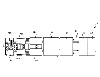
[0093] Referring to FIG. 8, a mobile pump system 82. The mobile pump system 82
may include
a trailer 84 attachable to a vehicle for moving the trailer 84 to various
locations. The mobile pump
system 82 may include a controller 86 mounted on the trailer 84, the
controller 86 in electrical
communication with other components of the mobile pump system 82 (e.g., an
electrical transformer
88, a variable frequency drive 90, a heat exchanger, an electric motor 94, a
pump 96, a secondary
pump 98, and a secondary electric motor 100). The controller 86 may
communicate control signals
to the other components to cause the other components to perform a
predetermined action (e.g.,
activating or deactivating a component, changing a pump rate, changing a heat
exchanger
temperature, and the like).
[0094] The mobile pump system 82 may include an electrical transformer 88
mounted on the
trailer 84. The electrical transformer 88 may increase or decrease a voltage
from an external power
source for use by one of the components of the mobile pump system 82. This may
allow components
of the mobile pump system 82 to be powered by an external power source not
included on the trailer
84 by electrically connecting the external power source to the transformer 88,
which may be
electrically connected to the other components.
[0095] The mobile pump system 82 may include the variable frequency drive 90
mounted on the
trailer 84. The variable frequency drive 90 may include an electro-mechanical
drive system to
control motor speed and/or torque of the electric motor 94 by varying motor
input frequency and/or
voltage.
[0096] The mobile pump system 82 may include the heat exchanger 92 mounted on
the trailer 84
to regulate temperature of at least one of the other components (e.g., the
electric motor 94 and/or the
pump 96), such that the component can operate more efficiently. The heat
exchanger 92 may
function as a cooler to prevent a component of the mobile pump system 82 from
overheating.
[0097] The mobile pump system 82 may include the electric motor 94 mounted on
the trailer 84,
the electric motor 94 as previously described herein. The mobile pump system
82 may also include
the pump 96a, 96b (a single or multiple pumps may be included) mounted on the
trailer 84. The
pump 96a, 96b may include the features previously described herein in
connection with pump 48.
The pump 96a, 96b may be driven by the electric motor 94.
[0098] With continued reference to FIG. 8 and referring to FIG. 11, the mobile
pump system 82
may include a secondary pump 98 and/or a secondary motor 100 (e.g., an
electric motor) mounted
16
CA 3042189 2019-05-03
on the trailer 84. The secondary pump 98 may include a triplex pump. The
secondary pump 98 may
be configured for pumping fluid at higher pressure compared to the pump 96a,
96b of the mobile
pump system 82. The secondary pump 98 may be selectively activated in
situations in which the
mobile pump system 82 is required to operate at a higher pressure. The
secondary pump 98 may be
isolated from the pump 96a, 96b of the mobile pump system. The secondary motor
100 may drive
the secondary pump 98. The pump 96a, 96b and/or the secondary pump 98 may be
in fluid
communication with the wellbore 12 (see FIG. 2).
[0099] Referring to FIG. 9, a mobile pump system 102 may include any of the
components
discussed in connection with the mobile pump system 82 from FIG. 8 and may
include any additional
or alternative components as hereinafter described. The trailer 84 may include
a connection portion
104 configured to engage with an engagement portion of a cab (e.g., a fifth
wheel). The connection
portion 104 may engage with a cab, such that the mobile pump system 102 may be
transported by
the cab to various locations, such as to and from a production site.
[00100] The mobile pump system 102 may include an inlet filter silencer 106
mounted on the
trailer 84 to reduce noise emitted by any of the components included in the
mobile pump system 102.
[00101] The mobile pump system 102 may include a turbine 108a, 108b (a single
or multiple
turbines may be included) mounted on the trailer 84 and connected to the pump
96a, 96b. The turbine
108a, 108b may be enclosed in a housing. The turbine 108a, 108b may be an on-
board (on the trailer
84) turbine to generate power on the trailer 84 for driving the pumps 96a,
96b. The turbine 108a,
108b may be directly coupled to the pump 96a, 96b via a gearbox 110a, 110b (a
single or multiple
gearboxes may be included), which may include gear reduction components. The
turbine 108a, 108b
may be powered by using field gas (e.g., natural gas) introduced to the
turbine to spin the turbine
blades to create power to rotate the pump 96a, 96b. The power generated by the
turbine 108a, 108b
may drive the pump 96a, 96b. The turbine 108a, 108b may be included in the
mobile pump system
102 in addition to or in lieu of the electric motor 94a, 94b shown in the
mobile pump system 82
shown in FIG. 8.
[00102] Referring to FIG. 10, a mobile pump system 112 may include all of the
components from
the mobile pump system 102 of FIG. 9 with the following additions or
alterations. The mobile pump
system 112 may include a fuel tank 114 (or multiple fuel tanks) mounted on the
trailer. The fuel
tank 114 may include any type of fuel suitable to fuel any of the components
of the mobile pump
system 112. Non-limiting examples of suitable fuels for the fuel tank 114
include compressed natural
gas (CNG), liquefied natural gas (LNG), diesel fuel, gasoline, propane,
butane, and other suitable
17
CA 3042189 2019-05-03
hydrocarbons and the like. The fuel tank 114 may be in fluid communication
with any of the
components of the mobile pump system 112 capable of being fueled by the fuel
contained in the fuel
tank 114. The fuel tank 114 may include any pumps, pipes, hoses, and/or valves
required to carry the
fuel to the relevant components of the mobile pump system 112.
[00103] The fuel tank 114 may be used as a backup fuel supply in the event of
a fuel supply
interruption. A fuel supply interruption may include the interruption of field
gas (e.g., natural gas
supplied directly from the production site at which the mobile pump system 112
is located) to the
mobile pump system 112. Inclusion of the fuel tank 114 on the trailer 84
allows the mobile pump
system 112 to continue operation even in the event of such a fuel supply
interruption, without the
deployment of an emergency backup power supply to the production site.
[00104] The mobile pump system 112 may include a conditioning system 116
configured to
condition the gas from the fuel tank 114 or the field gas supplied to the
mobile pump system 112.
The conditioning system 116 may include a gas heater to drop out solids and/or
water from the gas
and return it to the supply line. The conditioning system 116 may include at
least one filter to filter
out impurities in the fuel that could cause the system to malfunction.
[00105] Although the invention has been described in detail for the purpose of
illustration based
on what is currently considered to be the most practical and preferred
embodiments, it is to be
understood that such detail is solely for that purpose and that the invention
is not limited to the
disclosed embodiments, but, on the contrary, is intended to cover
modifications and equivalent
arrangements that are within the spirit and scope of the appended claims. For
example, it is to be
understood that the present invention contemplates that, to the extent
possible, one or more features
of any embodiment can be combined with one or more features of any other
embodiment.
18
CA 3042189 2019-05-03