Note: Descriptions are shown in the official language in which they were submitted.
CA 03042272 2019-04-29
WO 2018/093881
PCT/US2017/061775
LAYERED COMPOSITE ARTICLES AND METHODS OF MAKING SAME
CROSS-REFERENCE TO RELATED APPLICATIONS
100011 This application claims the benefit of priority to co-pending U.S.
Provisional
Application No. 62/422,308, filed on November 15, 2016 and to co-pending U.S.
Provisional
Application No. 62/553,271, filed on September 1, 2017, both of which are
incorporated
herein by reference in their entirety.
BACKGROUND
100021 Fiberboards, particularly medium-density fiberboards and high-
density
fiberboards, and plastic materials (such as PVC resins or other solid
thermoplastic or
thermoset polymers) are commonly used as core backing materials for floor
coverings, wall
coverings, and ceiling panels. For example, some existing floor panels
generally consist of a
chipboard core (such as an MDF or an HDF core), or a PVC core, which are
covered
(laminated) with a decor layer and a use surface or a finishing layer.
100031 Laminated floors have also proven to be a visually appealing,
economically
priced, relatively light weight flooring material, which can also be installed
by lay persons.
Furthermore, they are correspondingly widely spread. However, these laminated
floors
typically have relatively high impact noise, low radiant panel ratings, and
high environmental
impact. Many attempts have thus been made to develop composite boards based on
alternative materials.
100041 There is still a need, however, to obtain composite boards which do
not require a
complex layer structure in order to achieve characteristics suitable for being
used in heavy
duty applications. Still further, there is a need to obtain composite boards
having one or more
of high impact strength, swell heat resistance, heat retardance, dimensional
stability,
acceptable radiant panel ratings, and improved acoustical properties (such as
sound
propagation) as compared to existing fiberboards or composite boards.
100051 Still further, there is a need for methods that are capable of
manufacturing such
composite boards. These needs and other needs to be further described herein
can be at least
partially satisfied by one or more aspects of the present disclosure.
1
CA 03042272 2019-04-29
WO 2018/093881
PCT/US2017/061775
SUMMARY
100061 The present invention is directed to a layered composite article
that generally
comprises a rigid backing portion, the rigid backing portion comprising a
rigid core having a
first surface and an opposed second surface, wherein the rigid core comprises
at least one
densified fiber batt and wherein the at least one densified fiber batt is
comprised of a first
plurality of oriented fibers having a first melting point and a second
plurality of oriented
fibers having a second melting point different from the first melting point.
Further, the
layered composite also comprises a decorative portion having a first surface
and an opposed
second surface, wherein the second surface of the decorative portion is
affixed to the first
surface of the rigid core.
100071 In further aspects to be discussed in more detail below, at least
one of the first and
second pluralities of fibers comprises a multi-component fiber. In still
further aspects, the
multi-component fiber can comprise at least a first component having a first
melting point
and at least second component having a second melting point different from the
first melting
point. In still further aspects, the at least one densified fiber ban can
further comprise a third
plurality of oriented fibers comprising, for example, a natural fiber.
100081 in another aspect, the present disclosure provides a layered
composite article
generally comprising a rigid backing portion wherein the rigid backing portion
comprises a
rigid core having a first surface and an opposed second surface. The rigid
core further
comprises at least one densified fiber ban wherein the at least one densified
fiber ball is
comprised of first plurality of oriented fibers comprising a natural fiber
having a
decomposition temperature and a second plurality of oriented fibers having a
melting point
lower than the decomposition temperature of the first plurality of oriented
fibers. The layered
composite further comprises a decorative portion having a first surface and an
opposed
second surface, wherein the second surface of the decorative portion is
affixed to the first
surface of the rigid core.
100091 In still further aspects, disclosed herein is a layered composite
article comprising a
rigid backing portion, the rigid backing portion comprising a rigid core
having a first surface
and an opposed second surface, wherein the rigid core comprises at least one
densified fiber
batt and wherein the at least one densified fiber batt is comprised of a
plurality of oriented
multi-component fibers, wherein each of the plurality of oriented multi-
component fibers
2
CA 03042272 2019-04-29
WO 2018/093881
PCT/US2017/061775
comprises at least first component having a first melting point and at least
second component
having a second melting point different from the first melting point. This
layered composite
further comprises a decorative portion having a first surface and an opposed
second surface,
wherein the second surface of the decorative portion is affixed to the first
surface of the rigid
core.
100101 In still another aspect, the present disclosure provides a method of
making a layered
composite article as disclosed herein generally comprising the step of forming
a rigid backing
portion comprising a rigid core having a first surface and an opposed second
surface, wherein
the rigid core comprises at least one densified fiber batt and wherein the at
least one densified
fiber batt is comprised of a first plurality of oriented fibers having a first
melting point and a
second plurality of oriented fibers having a second melting point different
from the first
melting point. The method further comprises forming a decorative portion
having a first
surface and an opposed second surface and affixing the second surface of the
decorative
portion to the first surface of the rigid core.
100111 In yet another aspect, the present disclosure provides a method of
making a
layered composite article as disclosed herein generally comprising the step of
forming a rigid
backing portion comprising a rigid core having a first surface and an opposed
second surface,
wherein the rigid core comprises at least one densified fiber batt and wherein
the at least one
densified fiber batt is comprised of a plurality of oriented multi-component
fibers, wherein
each of the plurality of multi-component fibers comprises at least first
component having a
first melting point and at least second component having a second melting
point different
from the first melting point. The method further comprises forming a
decorative portion
having a first surface and an opposed second surface and affixing the second
surface of the
decorative portion to the first surface of the rigid core.
100121 In still another aspect, the present disclosure provides a method of
making a
layered composite article as disclosed herein generally comprising the step of
forming a rigid
backing portion comprising a rigid core having a first surface and an opposed
second surface,
wherein the rigid core comprises at least one densified fiber batt and wherein
the at least one
densified fiber ball is comprised of a first plurality of oriented fibers
comprising a natural
fiber having a decomposition temperature and a second plurality of oriented
fibers having a
melting point lower than the decomposition temperature of the first plurality
of oriented
fibers. The method further comprises forming a decorative portion having a
first surface and
3
CA 03042272 2019-04-29
WO 2018/093881
PCT/US2017/061775
an opposed second surface and affixing the second surface of the decorative
portion to the
first surface of the rigid core.
100131 In still further aspects, the step of forming the rigid backing
portion can further
comprise forming the rigid core by a method comprising overlaying the first
plurality of
oriented fibers and the second plurality of oriented fibers to form a fibrous
matrix; treating or
otherwise subjecting the fibrous matrix to conditions or process steps
effective to form a fiber
batt; and then heat and pressure treating the fiber batt under conditions
effective to form the
densified fiber batt.
100141 Additional aspects of the disclosure will be set forth, in part, in
the detailed
description, figures, and claims which follow, and in part will be derived
from the detailed
description, or can be learned by practice of the invention. It is to be
understood that both the
foregoing general description and the following detailed description are
exemplary and
explanatory only and are not restrictive of the invention as disclosed.
BRIEF DESCRIPTION OF DRAWINGS
100151 FIG. 1. is a schematic side view illustration of an exemplary
layered composite
floor covering as disclosed and described herein.
100161 FIG. 2 shows a schematic illustration of a 3-point bending flexural
test that can be
used to evaluate the exemplary layered composite articles disclosed herein.
100171 FIG. 3(a) shows a cross-section image of an exemplary conventional
flooring
covering comprising a PVC core and FIG. 3(b) shows a cross-section image of an
exemplary
flooring covering an inventive rigid core of the present disclosure.
100181 FIG. 4 is a schematic illustration of a process and apparatus for
forming a high
density composite according to various aspects of the present invention.
DETAILED DESCRIPTION
100191 The present invention can be understood more readily by reference to
the
following detailed description, examples, drawings, and claims, and their
previous and
following description. However, before the present articles, systems, and/or
methods are
disclosed and described in further detail, it is to be understood that this
invention is not
4
CA 03042272 2019-04-29
WO 2018/093881
PCT/US2017/061775
limited to the specific or exemplary aspects of articles, systems, and/or
methods disclosed
unless otherwise specified, as such can, of course, vary. It is also to be
understood that the
terminology used herein is for the purpose of describing particular aspects
only and is not
intended to be limiting.
100201 The following description of the invention is provided as an
enabling teaching of
the invention in its best, currently known aspect. To this end, those skilled
in the relevant art
will recognize and appreciate that many changes can be made to the various
aspects of the
invention described herein, while still obtaining the beneficial results of
the present invention.
It will also be apparent that some of the desired benefits of the present
invention can be
obtained by selecting some of the features of the present invention without
utilizing other
features. Accordingly, those of ordinary skill in the pertinent art will
recognize that many
modifications and adaptations to the present invention are possible and may
even be desirable
in certain circumstances and are a part of the present invention. Thus, the
following
description is again provided as illustrative of the principles of the present
invention and not
in limitation thereof.
DEFINITIONS
100211 As used herein, the singular forms "a," "an" and "the" include
plural referents
unless the context clearly dictates otherwise. Thus, for example, reference to
a "fiber"
includes aspects having two or more such fibers unless the context clearly
indicates otherwise.
100221 As used herein, the term "comprising" can include the aspects
"consisting of' and
"consisting essentially of." The term "comprising" can also mean "including
but not limited
to.,,
100231 Ranges can be expressed herein as from "about" one particular value,
and/or to
"about" another particular value. When such a range is expressed, another
aspect includes
from the one particular value and/or to the other particular value. Similarly,
when values are
expressed as approximations, by use of the antecedent "about," it will be
understood that the
particular value forms another aspect. It should be further understood that
the endpoints of
each of the ranges are significant both in relation to the other endpoint, and
independently of
the other endpoint. Moreover, in still further aspects, reference to a
parameter that equals a
particular endpoint or specific value also includes aspects that are
characterized as being
greater than the stated value or, alternatively, less than the stated value.
CA 03042272 2019-04-29
WO 2018/093881
PCT/US2017/061775
[0024) As used herein, the terms "optional" or "optionally" mean that the
subsequently
described event or circumstance may or may not occur, and that the description
includes
instances where said event or circumstance occurs and instances where it does
not.
100251 References in the specification and concluding claims to parts by
weight of a
particular element or component in a composition or article, denotes the
weight relationship
between the element or component and any other elements or components in the
composition
or article for which a part by weight is expressed. Thus, in a composition or
a selected
portion of a composition containing 2 parts by weight of component X and 5
parts by weight
component Y, X and Y are present at a weight ratio of 2:5, and are present in
such ratio
regardless of whether additional components are contained in the composition.
100261 A weight percent of a component, unless specifically stated to the
contrary, is
based on the total weight of the formulation or composition in which the
component is
included.
100271 The term "fiber" as used herein includes fibers of extreme or
indefinite length (i.e.
filaments) and fibers of short length (i.e., staple fibers). It is further
understood that the fiber
described herein can be construed as comprising materials of virgin or
recycled origin, or a
combination of both. In certain aspects of this invention, the fiber comprises
recycled
materials, wherein the recycled materials include, but are not limited, to
post-consumer or
post-industrial materials, or a combination thereof. In yet other aspects, the
fiber used in this
invention comprises virgin materials.
100281 The term "oriented fiber" as used herein is directed to the fiber
orientation in a
fiber batt or a fiber matrix.
100291 The term "rigid care" refers to any composite material comprising a
rigid core and
that is capable of withstanding heavy duty applications, such as for example,
heavy foot
traffic, without any significant deformation of the board. Still further, in
aspects of the
disclosure, a rigid composite board can be defined functionally in that it at
least substantially
prevents telegraphing of hard surface subfloor structure irregularities, such
as ripples and
waves, to the decorative layer portion when the rigid composite floor covering
is abutting the
subfloor structure in the selected orientation.
6
CA 03042272 2019-04-29
WO 2018/093881
PCT/US2017/061775
[0030) As used herein, the term "polyester" refers to a category of
polymers that contain
the ester functional group in their main chain. Polyesters disclosed herein
include naturally
occurring chemicals, such as in the cutin of plant cuticles, as well as
synthetics produced
through step-growth polymerization. An non-limiting example of polyesters
includes any
long-chain synthetic polymer composed of at least 85% by weight of an ester of
a substituted
aromatic dicarboxylic acid, including but not restricted to substituted
terephthalic units, p(-R-
0-00- C6H4-CO-04, and parasubstituted hydroxy-benzoate units, p(-R-O-CO-C61-14-
0)x. In
certain examples, the polyesters comprise polyethylene terephthalate (PET)
homopolymer
and copolymers, polypropylene terephthalate (PPT) homopolymer and copolymers
and
polybutylene terephthalate (PBT) homopolymer and copolymers, and the like,
including
those that contain comonomers such as cyclohexanedimethanol,
cyclohexanedicarboxylic
acid, isophthalic acid, and the like.
100311 The term "polyamide," as utilized herein, is defined to be any long-
chain polymer
in which the linking functional groups are amide (-CO-NH-) linkages. The term
polyamide is
further defined to include copolymers, terpolymers and the like as well as
homopolymers and
also includes blends of two or more polyamides. In some aspects, the plurality
of polyamide
fibers comprise one or more of nylon 6, nylon 66, nylon 10, nylon 612, nylon
12, nylon 11, or
any combination thereof. In other aspects, the plurality of polyamide fibers
comprises nylon
6 or nylon 66. In yet other aspect, the plurality of polyamide fibers is nylon
6. In a yet further
aspect, the plurality of polyamide fibers is nylon 66.
100321 As defined herein, the term "polyolefin" refers to any class of
polymers produced
from a simple olefin (also called an alkene with the general formula Cnfl2n)
as a monomer. In
some aspects, the polyolefins include, but are not limited to, polyethylene,
polypropylene,
both homopolymer and copolymers, poly(1-butene), poly(3-methyl-l-butene), poly-
methyl-
1-pentene) and the like, as well as combinations or mixtures of two or more of
the foregoing.
100331 As defined herein, the term "polyurethane" refers to any class of
polymers
composed of a chain of organic units joined by carbamate (urethane, R1-0-CO-
NR2-R3,
wherein RI. R2 and R3 are the same or different) links.
100341 As defined herein, the term "polystyrene" refers to any class of
synthetic polymers
produced from a simple styrene as a monomer. It is understood that the term
"polystyrene"
includes both atactic and syndiotactic polystyrenes. In some specific aspects,
described are
7
CA 03042272 2019-04-29
WO 2018/093881
PCT/US2017/061775
also co-polystyrenes including a high-impact polystyrenes (HIPS),
acrylonitrile butadiene
styrene (ABS) or copolymer of styrene with actylonitrile (SAN), or copolymer
of styrene
with maleic acid (SMA).
100351 As defined herein, the term "acetal" refers to a functional group
with the
following connectivity of R2C(OR')2, wherein both R' groups can comprise
hydrogen or
organic fragments. The two R'0 groups can be equivalent to each other (known
as a
symmetric acetal) or different (known as a mixed acetal).
100361 As used herein, the term "substantially" can in some aspects refer
to an amount or
feature that is represented or otherwise quantified as being at least about
80%, at least about
85%, at least about 90%, at least about 91%, at least about 92%, at least
about 93%, at least
about 94%, at least about 95%, at least about 96%, at least about 97%, at
least about 98%, at
least about 99%, or even about 100% of the stated property, component,
composition, or
other condition for which substantially is used to characterize or otherwise
quantify an
amount.
100371 In other aspects, as used herein, the term "substantially free,"
when used in the
context of a composition, or component of a composition that is substantially
absent, is
intended to refer to an amount that is less than about 1 % by weight, e.g.,
less than about
0.5 % by weight, less than about 0.143/0 by weight, less than about 0.05 % by
weight, or less
than about 0.01 % by weight of the stated material, based on the total weight
of the
composition.
100381 As used herein, the term or phrase "effective," "effective amount,"
or "conditions
effective to" refers to such amount or condition that is capable of performing
the function or
property for which an effective amount or condition is expressed. As will be
pointed out
below, the exact amount or particular condition required will vary from one
aspect to another,
depending on recognized variables such as the materials employed and the
processing
conditions observed. Thus, it is not always possible to specify an exact
"effective amount" or
"condition effective to." However, it should be understood that an appropriate
effective
amount will be readily determined by one of ordinary skill in the art using
only routine
experimentation.
100391 As used herein, and unless the context clearly indicates otherwise,
the term
"carpet" is used to generically include broadloom carpet, carpet tiles, area
rugs, and even
8
CA 03042272 2019-04-29
WO 2018/093881
PCT/US2017/061775
artificial grass (or turf). To that end, the term "broadloom carpet" refers to
a broadloom
textile flooring product manufactured for and intended to be used in roll
form. The term
"carpet tile" refers to a modular floor covering, conventionally manufactured
in 18" x 18,"
24" x 24" or 36" x 36" squares, but other sizes and shapes are also within the
scope of the
present invention. Any of these exemplary carpets can be woven, non-woven,
tufted, or
needle-punched.
100401 As used herein, the term "reclaimed fiber" includes a fiber
reclaimed from a new
product, post-industrial product, manufacturing remnants, quality control
discarded or
rejected material, or a post-consumer product. In some exemplary aspects, such
products
comprise carpets or carpet tiles.
100411 As used herein, the term "post-consumer fiber" refers to a fiber
that was a
component part of a product previously in use by a consumer. The post-consumer
fibers
include fibers reclaimed from the products that have been used in residential,
commercial,
and industrial applications, and subsequently have been collected from the
site of use or
otherwise discarded.
[00421 As used herein, the term "post-industrial fiber" refers to a fiber
reclaimed from a
product that is a byproduct from manufacturing that has been diverted from the
manufacturing waste stream.
100431 As used herein, the term "acclimation period" refers to a period of
time required
for one or more components in the layered composite article to adjust or
condition to equalize
differing stresses that may be present in the various components. In some
aspects, the lack of
an "acclimation period" can refer to the lack of an acclimation period
associated with
assembly of the various component parts during manufacture of the layered
composite article
of the present disclosure. In other aspects, an acclimation period can refer
to a period of time
or lack thereof needed between product arrival at a site of installation and
actual installation
of the product.
100441 While aspects of the present invention can be described and claimed
in a
particular statutory class, such as the system statutory class, this is for
convenience only and
one of ordinary skill in the art will understand that each aspect of the
present invention can be
described and claimed in any statutory class. Unless otherwise expressly
stated, it is in no
way intended that any method or aspect set forth herein be construed as
requiring that its
9
CA 03042272 2019-04-29
WO 2018/093881
PCT/US2017/061775
steps be performed in a specific order. Accordingly, where a method claim does
not
specifically state in the claims or descriptions that the steps are to be
limited to a specific
order, it is no way intended that an order be inferred, in any respect. This
holds for any
possible non-express basis for interpretation, including matters of logic with
respect to
arrangement of steps or operational flow, plain meaning derived from
grammatical
organization or punctuation, or the number or type of aspects described in the
specification.
100451 The present invention may be understood more readily by reference to
the
following detailed description of various aspects of the invention and the
examples included
therein and to the Figures and their previous and following description.
ARTICLE
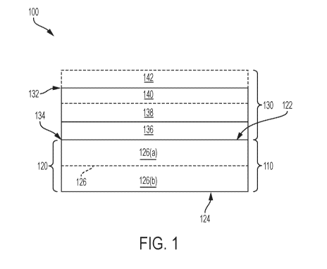
[0046] In some aspects, and as generally depicted in FIG. 1, described
herein is a layered
composite article 100, comprising: a) a rigid backing portion 110 comprising a
rigid core 120
having a first surface 122 and an opposed second surface 124, wherein the
rigid core
comprises at least one densified fiber batt 126 and wherein the at least one
densified fiber batt
is comprised of a first plurality of oriented fibers having a first melting
point and a second
plurality of oriented fibers having a second melting point different from the
first melting
point; and b) a decorative portion 130 having a first surface 132 and an
opposed second
surface 134, wherein the second surface of the decorative portion is affixed
to the first surface
of the rigid core.
100471 In some aspects, the densified fiber batt has a density in the range
of from about 5
lb/ft3 to about 100 lb/ft3, including exemplary densities of 10, 15, 20, 25,
30, 35, 40, 45, 50,
55, 60, 65, 70, 75, 80, 85, 90, and 95 lb/ft3. In still further aspects, the
volumetric density can
be a value within any range derived from the above values, including for
example, a density
of from about 15 to about 75 lb/ft3.
100481 In certain aspects, the densified fiber batt can have a density of
at least about 10
lblft3, including exemplary values of at least about 15 lb/ft3, about 20
lb/ft3, about 25 lb/ft3,
about 30 lb/ft3, about 35 lb/ft3, about 40 lb/113, about 45 lb/ft3, or about
50 lb/ft3. In certain
aspects, the densified fiber batt can have a density in a range between any
two foregoing
values.
CA 03042272 2019-04-29
WO 2018/093881
PCT/US2017/061775
100491 In yet other aspects, the densified fiber batt can have a density no
greater than
about 50 lb/ft3. about 45 lb/ft3, about 40 lb/113, about 35 lb/ft3, about 30
lb/ft3, 25 lb/ft3, about
20 lb/ft', about 15 lb/ft3, or about 10 lb/ft3. In certain aspects, the
densified fiber batt can
have a density in a range between any two foregoing values. It is understood
that the
densified batt can have a density as low as a density of a fiber batt
comprising a substantially
identical first plurality of oriented fibers and a substantially identical a
second plurality of
oriented fibers that has not undergone any densification processes, for
example heat treating
or pressure treating processes.
100501 In yet other aspects, the rigid core of the inventive layered
composite article can
have multiple regions or portions of vaiying or differing densities. For
example, the rigid
core of the layered composite can comprise a first portion 126(a) having a
first density and a
second portion 126(b) having a second density different from the first
density. In some
aspects, the first portion of the rigid core is adjacent to the first surface
of the rigid core. In
other aspects, the second portion of the rigid core is adjacent to the second
surface of the rigid
core. In certain aspects, the first density is larger than the second density.
In still other
aspects, the first density is lower than the second density. These portions of
varying densities
can occur within a single fiber batt or can be provided by the presence of
more than one fiber
bans layered amongst each other.
100511 In still further aspects, the rigid core can comprise at least two
densified fiber
bans. For example, again as illustrated in FIG. 1, first and second portions
126(a) and
126(b) can also represent the presence of two fiber bans. In aspects where two
or more
densified fiber baits are present, each of the densified fiber bans exhibits a
density that can be
the same or different from another densified batt. In some aspects, the rigid
core can
comprise a first densified fiber batt having a third density and a second
densified fiber ban
having a fourth density. In some aspects, the third density is larger than the
fourth density. In
yet other aspects, the third density is lower than the fourth density. In
certain aspects, the
first densified fiber batt is adjacent to the first surface of the rigid core,
while the second
densified fiber batt is adjacent to the second surface of the rigid core. In
aspects where more
than two densified fiber bans are present, each of the densified fiber baits
can be arranged in
any configuration determined by one of ordinary skill in the art and useful
for a final
application. In these aspects, each of the densified fiber baits can exhibit
same or a different
density.
11
CA 03042272 2019-04-29
WO 2018/093881
PCT/US2017/061775
[0052) In still further aspects, the inventive rigid core can exhibit a
density that is lower
than a density of a conventional rigid backing portion comprising a layer of
polyvinyl
chloride material or a wood based material as a core, and wherein such
conventional rigid
backing is absent of a densified fiber batt. In yet other aspects, the
inventive rigid core
exhibits a higher porosity than a comparable conventional rigid backing
portion comprising a
layer of polyvinyl chloride material or a wood material as a core, and wherein
such
conventional rigid backing is absent of a densified fiber batt.
100531 in still further aspects, the layered composite can optionally
comprise a densified
la) er comprising a non-fibrous composition. For example, the densified layer
of non-fibrous
composition can be a densified powder layer. The densified powder composition
can
comprise a polymer powder. In still further aspects, the polymer powder can
comprise a
polypropylene, a polyester, a polyethylene, or a combination thereof. In still
further aspects,
such layer can be formed by scattering the polymer powder using a powder
scattering
machine. The optional densified non-fibrous layer can be positioned at any
desired location
within the layered composite structure. For example, the densified non fibrous
layer can be
positioned between the top surface of the rigid core layer and the decorative
portion. In this
aspect, the densified non-fibrous layer can optionally serve as a substrate
for printing an ink
layer. This together can form a decorative portion or layer as described
further herein. In
still further aspects, the densified non-fibrous layer can increase the
density of the rigid core
to resist indentation during an extensive use.
100541 In certain aspects, the first and second plurality of oriented
fibers can have a
substantially random orientation, a substantially uniform orientation, or any
variation of a
predetermined orientation that is between a random and uniform orientation.
Still further, the
plurality of fibers can itself comprise any desired combination of various
orientations. In
some aspects, the first plurality of oriented fibers is substantially randomly
oriented. In yet
other aspects, the first plurality of oriented fibers is uniformly oriented.
In still further
aspects, the first plurality of oriented fibers in arranged in a predetermined
orientation.
100551 In some aspects, the second plurality of oriented fibers is
substantially randomly
oriented. In yet other aspects, the second plurality of oriented fibers is
uniformly oriented. In
still further aspects, the second plurality of oriented fibers in arranged in
a predetermined
orientation.
12
CA 03042272 2019-04-29
WO 2018/093881
PCT/US2017/061775
100561 In still further aspects, the first and the second plurality of
oriented fibers can have
the same or different orientation. In some exemplary aspects, the first
plurality of oriented
fibers can have a substantially random orientation, while the second plurality
of oriented fiber
can have a uniform orientation. In yet other exemplary aspects, the first
plurality of oriented
fibers can have a uniform orientation, while the second plurality of oriented
fibers is
substantially randomly oriented. In still further aspects, both the first and
the second plurality
of oriented fibers can have the same orientation.
100571 in certain aspects, the first and second plurality of oriented
fibers can comprise a
staple fiber, a bulk continuous fiber (BCF), or a combination thereof. In some
aspects, the
first plurality of oriented fibers can comprise a staple fiber. In other
aspects, the first plurality
of oriented fibers can comprise a bulk continuous fiber. In yet other aspects,
the first
plurality of oriented fibers can comprise both staple and bulk continuous
fiber.
100581 In other aspects, the second plurality of oriented fibers can
comprise a staple fiber.
In other aspects, the second plurality of oriented fibers can comprise a bulk
continuous fiber.
In yet other aspects, the second plurality of oriented fibers can comprise
both staple and bulk
continuous fiber.
100591 In still further aspects, the first plurality of oriented fibers can
comprise a staple
fiber, while the second plurality of oriented fibers can comprise a bulk
continuous fiber. In
yet other aspects, the first plurality of oriented fibers can comprise a bulk
continuous fiber,
while the second plurality of oriented fibers can comprise a staple fiber. In
still further
aspects, both first and second plurality of oriented fibers can comprise a
staple fiber. In yet
other aspects, both first and second plurality of oriented fibers can comprise
a bulk
continuous fiber.
100601 According to certain aspects, the first and second plurality of
oriented fiber can
exhibit a substantially uniform size, including substantially uniform liner
density measured in
denier units and substantially uniform fiber lengths. However, in alternative
aspects, fibers
present within the first and second plurality of oriented fiber can have non-
uniform linear
densities and non-uniform fiber lengths. According to these aspects, the
population of the
first and second plurality of oriented fibers having non-uniform linear fiber
densities can, for
example, have individual linear fiber densities in the range of from about 1
to about 500
denier, including exemplary values of about 3 denier, about 5 denier, about 10
denier, about
13
CA 03042272 2019-04-29
WO 2018/093881
PCT/US2017/061775
15 denier, about 20 denier, about 25 denier, about 30 denier, about 35 denier,
about 40 denier,
about 45 denier, about 50 denier, about 60 denier, about 70 denier, about 80
denier, about 90
denier, about 100 denier, about 120 denier, about 150 denier, about 170
denier, about 200
denier, about 250 denier, about 300 denier, about 350 denier, about 400
denier, and about 450
denier. It is further understood that the population of the first and second
plurality of oriented
fibers can have individual linear fiber density in any range between two
foregoing values.
For example, in certain aspects, the individual linear fiber density can be
from about 1 to
about 5 denier, from about 5 denier to about 25 denier, from about 5 denier to
about 200
deniers, or from about 100 denier to about 500 denier. Still further, a
population of the first
and second plurality of oriented fibers having non-uniform linear density can
collectively
provide an average linear fiber density that is, for example, greater than 5
denier, greater than
denier, greater than 15 denier, greater than 20 denier, greater than 25
denier, greater than
30 denier, greater than 35 denier, greater than 40 denier greater than 45
denier, greater than
50 denier, greater than 100 denier, greater than 200 denier, greater than 300
denier, or even
greater than 400 denier.
100611 In other aspects, the first and second plurality of oriented fibers,
each
independently can comprise polyester, polypropylene, polyethylene, polyamides,
polyurethane, polylactic acid, acetal, co-polyester, co-polyamide,
polystyrene, or a
combination thereof.
100621 Exemplary fibers present in the first and/or second plurality of
oriented fibers can
include polyamides, polyester, polypropylene, polyethylene, polyurethane,
polyethylene
terephthalate, polytrimethylene terephthalate, latex, styrene butadiene
rubber, or any
combination thereof.
100631 In some aspects, the densified fiber can further comprise a third
plurality of
oriented fibers. In such aspects, the third plurality of oriented fiber has a
third melting point
different from the first melting point of the first plurality of fibers or the
second melting point
of the second plurality of fibers. In some aspects the third plurality of
oriented fibers can be
natural fibers. In yet other aspect, the natural fibers exhibit a
decomposition point. In yet
other aspects, the third plurality of oriented fibers can comprise a staple
fiber, a bulk
continuous fiber, or a combination thereof.
14
CA 03042272 2019-04-29
WO 2018/093881
PCT/US2017/061775
[0064) In yet other aspects, the natural fibers comprise bast fibers,
cotton, cellulose,
wool, silk, linen, mineral, coconut, glass, or any combination thereof.
100651 In some aspects, the third plurality of oriented fibers can have a
substantially
random orientation. In yet other aspects. the third plurality of oriented
fibers can have a
substantially uniform orientation. In still further aspects, the third
plurality of oriented fibers
can have a predetermined orientation.
100661 In still further aspects, the third plurality of oriented fiber can
exhibit a
substantially uniform size, including substantially uniform liner density
measured in denier
units and substantially uniform fiber lengths. However, in alternative
aspects, fibers present
within the third plurality of oriented fiber can have non-uniform linear
densities and non-
uniform fiber lengths. According to these aspects, a population of the third
of oriented fibers
having non-uniform linear fiber densities can, for example, have individual
linear fiber
densities in the range of from about 1 to about 500 denier, including
exemplary values of
about 3 denier, about 5 denier, about 10 denier, about 15 denier, about 20
denier, about 25
denier, about 30 denier, about 35 denier, about 40 denier, about 45 denier,
about 50 denier,
about 60 denier, about 70 denier, about 80 denier, about 90 denier, about 100
denier, about
120 denier, about 150 denier, about 170 denier, about 200 denier, about 250
denier, about 300
denier, about 350 denier, about 400 denier, and about 450 denier. It is
further understood that
the population of the first and second plurality of oriented fibers can have
individual linear
fiber density in any range between two foregoing values. For example, in
certain aspects, the
individual linear fiber density can be from about 1 to about 5 denier, from
about 5 denier to
about 25 denier, from about 5 denier to about 200 deniers, or from about 100
denier to about
500 denier. Still further, a population of the first and second plurality of
oriented fibers
having non-uniform linear density can collectively provide an average linear
fiber density
that is, for example, greater than 5 denier, greater than 10 denier, greater
than 15 denier,
greater than 20 denier, greater than 25 denier, greater than 30 denier,
greater than 35 denier,
greater than 40 denier greater than 45 denier, greater than 50 denier, greater
than 100 denier,
greater than 200 denier, greater than 300 denier, or even greater than 400
denier.
100671 In yet other aspects, it is understood that the decomposition point
of the fibers
present in the third plurality of oriented fibers is higher than the first
and/or second melting
point such that heat treatment effective to result in melting and
consolidation of at least one
CA 03042272 2019-04-29
WO 2018/093881
PCT/US2017/061775
of the first and second pluralities of fibers does not result in any
substantial decomposition of
natural fibers present.
100681 In still further aspects, the layered composite article can comprise
a) a rigid
backing portion comprising a rigid core having a first surface and an opposed
second surface,
wherein the rigid core comprises at least one densified fiber batt and wherein
the at least one
densified fiber batt is comprised of first plurality of oriented fibers
comprising a natural fiber
having a decomposition temperature and a second plurality of oriented fibers
having a
melting point lower than the decomposition temperature of the first plurality
of oriented
fibers; and b) a decorative portion having a first surface and an opposed
second surface,
wherein the second surface of the decorative portion is affixed to the first
surface of the rigid
core. It is understood that in these aspects, the first plurality of oriented
fiber comprising
natural fibers can be any natural fibers listed above. It is further
understood that the second
plurality of oriented fibers can comprise any foregoing fibers, or any fibers
described below.
100691 In yet other aspects, where the first plurality of fibers is not a
natural fiber, the
first plurality of fibers can comprise a multi-component fiber. In yet other
aspects, the
second pluralities of fibers can comprise a multi-component fiber. It is
understood that in
some aspects of the present invention, the multi-component fibers can be
defined as
"extruding two polymers from the same spinneret with both polymers contained
within the
same filament." In some aspects, multi-component fibers can have any cross
sectional shape
or geometry that can be contemplated by one of ordinary skill in the art. In
some aspects, the
multi-component fibers can have cross-section structures that include but are
not limited to
side-by-side fiber, sheath-core fiber, islands-in-the-sea fiber and segmented-
pie cross-section
types.
100701 It is understood that in some aspects, the multicomponent fiber can
comprise at
least first component having the first melting point and at least second
component having the
second melting point different from the first melting point. It is further
understood that in
some aspects, the at least first component can comprise a polymeric component.
In yet other
aspects, the at least second component can comprise a polymeric component.
100711 In yet other exemplary aspects, the multi-component fibers comprise
a sheath-core
configuration. In some aspects, the sheath comprises the first component. In
yet other
aspects, the core comprises a second component. In yet other aspects, the
sheath can
16
CA 03042272 2019-04-29
WO 2018/093881
PCT/US2017/061775
comprise a second component and the core can comprise the first component. It
is
understood that both sheath and core can comprise any mentioned above fibers
as a
component. In some aspects, the polymeric core component can have a higher
melting point
than the polymeric sheath component. In some aspects, the polymeric core
component can
comprise polyester, aliphatic polyamides, polyphenylene oxide and/or co-
polymers or blends
thereof. In yet other aspects, the polymeric core component can comprise
polyester,
polypropylene, polyethylene, polyamides, polyurethane, polylactic acid,
acetal, co-polyester,
co-polyamide, polystyrene, or a combination thereof. In yet other aspects, the
polyester can
comprise polyethylene terephthalate, polybutylene terephthalate, or
polyparaphenylene
terephthalamide. In yet other aspects, the polymeric core comprises
polyethylene
terephthalate. In further aspects, the sheath polymer can comprise a
polyamide, polyethylene,
or polyester. In still further aspects, the sheath polymer can comprise
polyester,
polypropylene, polyethylene, poly amides, polyurethane, polylactic acid,
acetal, co-polyester,
co-polyatnide, polystyrene, or a combination thereof. In yet further aspects,
the sheath
polymer can comprise a nylon, or polypropylene. In still further aspects, the
sheath-core
multi-component fiber comprises a polyester as a core component and nylon as a
sheath
component.
100721 It is further understood that in some aspects the sheath and core of
the multi-
component fiber can comprise the same polymer having different melting points.
In still
further aspects, the sheath-core multi-component fiber comprises a polyester
as a core
component and polyethylene as a sheath component. In still further aspects,
the sheath-core
multi-component fiber comprises a polyester having the first melting point as
a core
component and a polyester having the second melting point as a sheath
component.
100731 It is understood that in aspects, where the multi-component fiber is
used in a
combination with the natural fiber, the melting point of each component in the
multi-
component fiber is lower than the decomposition temperature of the natural
fiber.
100741 In some aspects, the at least one densified fiber bat described
herein can comprise
a first plurality of oriented fibers having a first melting point, wherein the
first plurality of
oriented fibers comprises a single-component fiber. In yet other aspects, the
at least one
densified fiber batt described herein can comprise a second plurality of
oriented fibers
comprising a multi-component fiber comprising at least first component having
the first
melting point and at least second component having a second melting point.
17
CA 03042272 2019-04-29
WO 2018/093881
PCT/US2017/061775
100751 In yet other aspects, the at least one densified fiber batt
described herein
comprises a plurality of oriented multi-component fibers, wherein each of the
plurality of
oriented multi-component fibers comprises at least first component having a
first melting
point and at least second component having a second melting point different
from the first
melting point. In these aspects, the plurality of oriented multi-component
fibers can comprise
any multi-component fiber configurations described herein. In yet other
aspects, any
disclosed herein polymers can be used as any component of the plurality of
oriented multi-
component fibers.
100761 In still further aspects, the rigid core is substantially free of a
PVC material, or
high density fiber (HDF) derived from a wood based material, or medium density
fiber
(MDF) derived from a wood based material. In still further aspects, the rigid
core is
substantially free of a wood based material.
100771 In yet other aspects, the rigid core can further comprise a filler
component.
Exemplary and non-limiting fillers that can be incorporated into the rigid
core layer can
include calcium carbonate, fly-ash, recycled calcium carbonate, aluminum
trihydrate, talc,
nano-clay, barium sulfate, barite, barite glass fiber, glass powder, glass
cullet, metal powder,
alumina, hydrated alumina, clay, magnesium carbonate, calcium sulfate, silica,
glass, fumed
silica, carbon black, graphite, cement dust, feldspar, nepheline, magnesium
oxide, zinc oxide,
aluminum silicate, calcium silicate, titanium dioxide, titanates, glass
inicrospheres, chalk,
calcium oxide, and any combination thereof. In some aspects, the filler
content can be virgin.
In other aspects, the filler content can be reclaimed. In certain aspects, the
filler content can
be reclaimed from post-consumer articles. In yet other aspects, the filler
content can be
reclaimed from post-industrial articles.
100781 In certain aspects, the filler comprises one or more of calcium
carbonate,
aluminum trihydrate, barite, feldspar, cullet, fly ash, kaolin clay,
limestone, polyurethane
foam, rubber, thermoplastic powder, thermoplastic polyurethane (TPU),
wollastonite, or any
combination thereof.
100791 In yet other aspects, the rigid core can further comprise a pigment,
a flame
retardant, surfactant, processing aids, or a combination thereof. In certain
aspects, the rigid
core can comprise one or more flame retardant components. Exemplary flame
retardants that
can be incorporated into the rigid core include, without limitation, organo-
phosphorous flame
18
CA 03042272 2019-04-29
WO 2018/093881
PCT/US2017/061775
retardants, red phosphorous magnesium hydroxide, magnesium dihydroxide,
hexabromocyclododecane, bromine containing flame retardants, brominated
aromatic flame
retardants, melamine cyanurate, melamine polyphosphate, melamine borate,
methylol and its
derivatives, silicon dioxide, calcium carbonate, resourcinol bis-(diphenyl
phosphate),
brominated latex base, antimony trioxide, strontium borate, strontium
phosphate, monomeric
N-alkoxy hindered amine (NOR HAS), triazine and its derivatives, high aspect
ratio talc,
phosphated esters, organically modified nanoclays and nanotubes, non-
organically modified
nanoclays and nanotubes, ammonium polyphosphate, polyphosphoric acid, ammonium
salt,
trialy1 phosphates, isopropylated triphenyl phosphate, phosphate esters,
magnesium
hydroxide, zinc borate, bentonite (alkaline activated nanoclay and nanotubes),
organoclays,
aluminum trihydrate (ATH), azodicarbonamide, diazenedicarboxamide,
azodicarbonic acid
diamide (ADC), triaryl phosphates, isopropylated triphenyl phosphate, triazine
derivatives,
alkaline activated organoclay and aluminum oxide. Any desired amount of flame
retardant
can be used in the rigid core and the selection of such amount will depend on
a required
application. Such amounts can be readily determined through no more than
routine
experimentation.
100801 In other aspects, any pigments or surfactant known in the art can be
utilized. In
yet other aspects, any processing aids known in the art can be used. In some
aspects,
processing aids can include without limitation antistatic chemicals,
lubricants, oils, or any
combination thereof.
100811 In yet other aspects, at least one of the first or second
pluralities of fibers, or even
of the third pluralities of fibers, when present, can comprise reclaimed
fibers. In some
aspects, the reclaimed fibers can comprise a post-consumer fiber. In still
further aspects, the
reclaimed fibers can comprise a post-industrial fiber. In still further
aspects, the reclaimed
fibers can comprise both a post-consumer and post-industrial fiber. It is
understood that the
both post-consumer and post-industrial fibers can comprise any fibers
described above. It is
understood that in some aspects, the reclaimed fiber is reclaimed from a
carpet or carpet tile.
In yet other aspects, the reclaimed fiber can be fiber reclaimed from any
material, for
example any material comprising polymeric and/or natural fibers.
100821 The reclaimed fibers can be present in the final rigid core in any
desired amount,
including for example an amount in the range of from greater than 0% to 100 %
by weight,
including exemplary amounts of 5%, 10%, 15%, 20%, 25%, 30%, 35%, 40%, 45%,
50%,
19
CA 03042272 2019-04-29
WO 2018/093881
PCT/US2017/061775
55%, 60%, 65%, 70%, 75%, 80%, 85%, 90%, and 95%. In still further aspects, the
reclaimed
fibers can be present in an amount within any range derived from the above
values, including
for example, an amount in the range of from greater than 0 weight percent to
90 weight
percent, from 30 weight percent to 70 weight percent, or from 40 weight
percent to 60 weight
percent. In still other aspects, the layered composite article can comprise at
least about 10%,
at least about 20%, at least about 30%, at least about 40%, or at least about
50% by weight of
reclaimed material, such as post-consumer material, post-industrial material,
post-commercial
material, or a combination thereof In another aspect, the layered composite
article comprises
from about 50% to about 100% by weight of reclaimed material. It is further
understood that
the reclaimed material in the layered composite article can be present as
reclaimed fibers,
reclaimed fillers, or a combination thereof
100831 It is understood that by incorporating reclaimed material into the
inventive layered
composite articles several advantages can be realized. For example, second
generation
products incorporating the reclaimed material have less of an environmental
footprint relative
to traditional composites, comprising only virgin materials. In a further
aspect, the use of
reclaimed material reduces the amount of traditional, often environmentally
harmful
materials that previously were sent to landfill, while still providing the
same or similar level
of composite performance. Still further, substitution of virgin material with
reclaimed
material can reduce the manufacturing costs associated with producing various
composite
products, such as floor covering products. Additionally, the incorporation of
reclaimed
material into a second generation composite can also provide mechanical
reinforcement or
stability to the second generation composite, if desired.
100841 In certain aspects, it is understood that the first plurality of
oriented fibers, the
second plurality of oriented fibers, and the third plurality of oriented
fibers described herein
can be present in any amount to provide the rigid core having a desired
density. It is
understood that the first, second and third pluralities of oriented fibers can
be present in any
ratio to provide the rigid core having a desired density.
100851 In some aspects, the plurality of oriented fibers having a lowest
melting point can
be present in the final rigid core (or in the densified fiber bait) in any
desired amount,
including for example an amount in the range of from greater than 0% up to 100
% by
weight, including exemplary amounts of 5%, 10%, 15%, 20%, 25%, 30%, 35%, 40%,
45%,
50%, 55%, 60%, 65%, 70%, 75%, 80%, 85%, 90%, 95%, and 100%. In still further
aspects,
CA 03042272 2019-04-29
WO 2018/093881
PCT/US2017/061775
the plurality of oriented fibers having a lowest melting can be present in an
amount within
any range derived from the above values, including for example, an amount in
the range from
about 0% to about 80% by weight of the total amount of fibers present in the
densified fiber
bait, alternatively from about 5% to about 60% by weight of the total amount
of fibers
present in the densified fiber batt, alternatively from about 3004) to about
50% by weight of
the total amount of fibers present in the densified fiber bat or still
alternatively from about
40% to about 60% by weight of the total amount of fibers present in the
densified fiber bait.
In the aspects, wherein the at least one plurality of oriented fibers
comprises a multi-
component fiber, the ratio between various components having different melting
points in the
multi-component fiber can be any ratio chosen by one of ordinary skill in the
art. In some
aspects, wherein two components are presents, the ratio by the weight between
two
components having different melting points can be from about 0.1, about 0.2,
about 0.3,
about 0.4, about 0.5, about 0.6, about 0.7, about 0.8, about 0.9, or I.
100861 In aspects wherein the at least first plurality of oriented fibers
comprises a multi-
component fiber, at least a first component of the multi component fiber can
have a first
melting point and at least a second component of the multi component fiber can
have a
second melting point different from the first component melting point.
Further, the second
plurality of oriented fibers can comprise a plurality of single-component
fibers, wherein the
single-component fiber can also have approximately the same melting point as
the first
melting point of the first multi-component component Still further, the ratio
between the
first plurality of fibers and the second plurality of fibers can be any
desired value intended to
result in a fiber bait having a predetermined desired density. In some
exemplary aspects, the
multi-component fiber can be present in an amount from greater than 0 to 100%
by weight,
including exemplary values of about 1%, about 5 %, about 10%, about 20%, about
30%,
about 40%, about 50%, about 60%, about 70%, about 80%, about 90%, about 95%,
about
99%, and about 99.9%. In some aspects, the multi-component fiber can be
present in 100 %
by weight.
100871 In certain aspects, the rigid core can have a thickness in the range
from about 0.5
mm to about 12 mm, including exemplary values of about 1 mm, about 2 mm, about
3 mm,
about 4 mm, about 5 mm, about 6 mm, about 7 mm, about 8 mm, about 9 mm, about
10 mm,
and about 11 mm. In still further aspects, the rigid core can have a thickness
in any range
between two foregoing values. In some aspects, the thickness can be in the
range from about
21
CA 03042272 2019-04-29
WO 2018/093881
PCT/US2017/061775
0.5 mm to about 12 mm, from about 2 mm to about 12 mm, or from about 5 mm to
about 12
mm.
100881 In some aspects, the inventive rigid core can be permeable to
moisture. In yet
other aspects, the inventive rigid core is impermeable to moisture. In still
further aspects, the
inventive rigid core does not accumulate or hold moisture within the densified
fiber batt. It is
further understood that in some aspects the presence of moisture does not
alter the rigid core.
In certain aspects, moisture does not alter mechanical properties of the rigid
core. In yet other
aspects, the rigid core exhibits a moisture vapor transmission rate of greater
than about 3
pounds per 1,000 ft2 per 24 hours, greater than about 3.5 pounds per 1,000 ft2
per 24 hours,
greater than about 4 pounds per 1.000 ft2 per 24 hours, greater than about 4.5
pounds per
1,000 ft2 per 24 hours, or greater than about 5 pounds per 1,000 ft2 per 24
hours.
100891 As summarized above and as again illustrated in FIG. 1, the layered
composite
article comprises a decorative portion 130 having a first surface 132 and an
opposed second
surface 134, wherein the second surface of the decorative portion is affixed
to the first surface
of the rigid core. In certain aspects, the decorative portion of the inventive
article comprises
a decorative substrate layer or a decorative surface layer 136. As used
herein, it should be
understood that the term decorative substrate layer and decorative surface
layer can be used
interchangeably. In some aspects, the decorative surface layer comprises
polyvinyl chloride
(PVC), whitened PVC, opaque PVC, oriented polypropylene (OPP), polyolefin
(PO), woven
polyethylene (PE), non-woven PE, woven polypropylene (PP), nonwoven PP, woven
PET,
whitened fiber PET, nonwoven PET, woven nylon, nonwoven nylon, conventional
paper,
conventional foil, or foiled oriented polypropylene. In still further aspects,
the decorative
surface layer can comprise one or more of a heat stabilized biaxially-oriented
PET (BoPET),
amorphous PET (aPET), recycled PET (rPET), polyethylene terephthlate glycol-
modified
(PETG), polyolefin, cyclic olefin copolymer (COC), cyclic olefin polymer
(COP),
polyvinylidene fluoride (PVDF), polylactic acid (PLA) copolymers, nylon,
cellulose acetate,
poly(methyl methaciylate) (PMMA), thermoplastic polyurethane (TPU),
thermoplastic
elastomers (TPS), polycarbonate, polyethylene (PE), or a copolymer thereof.
100901 In certain aspects, the decorative surface or substrate layer has a
thickness from
about 0.5 mil to about 20 mil, including exemplary values of about 2 mil,
about 3 mil, about 4
mil, about 5 mil, about 6 mil, about 7 mil, about 8 mil, about 9 mil, about 10
mil, about 11
mil, about 12 mil, about 13 mil, about 14 mil, about 15 mil, about 16 mil,
about 17 mil, about
22
CA 03042272 2019-04-29
WO 2018/093881
PCT/US2017/061775
18, mil, and about 19 mil. In still further aspects, the decorative surface or
substrate layer can
have any thickness in a range derived from any two of the above listed
exemplary values.
For example, the substrate layer can comprise a thickness in a range of from
about 0.5 mil to
about 5 mil, or from about 3 mil to about 7 mil, or from about 7 mil to about
20 mil. In still
further aspects, the substrate layer can be a film.
100911 In yet other aspects, the decorative portion comprises an image
layer 138. In
certain aspects, the image layer is printed or otherwise transferred on a
surface of the
decorative substrate layer or the decorative surface layer. In yet other
aspects, the image
layer is printed or otherwise transferred on a surface of any visible layer.
In some aspects,
the substrate layer and the visible layer are the same. In other aspects, the
substrate layer and
the visible layer are different.
[00921 In some aspects, the decorative layer is affixed to the first
surface of the rigid core
with an adhesive. It is understood that the adhesive can be any adhesive known
in the art. In
some aspects, the adhesive comprises at least one of aciylic adhesive,
ethylene-vinyl acetate
(EVA), ethylene-acrylic acid (EAA), ethylene-acrylic acid-maleic anhydride
(EAA-MAH),
ethylene-methyl acrylate-maleic anhydride (EMA-MAH), ethylene-vinyl acetate-
maleic
anhydride (EVA-MAH), low density-polyethylene ¨maleic anhydride (LDPE-MAH),
high
density polyethylene-maleic anhydride (HDPE-MAH), polyurethane (PUR),
polyurethane
dispersions (PUD), a polyester hotmelt, a UV-curable adhesive, or a
combination thereof. In
some aspects, the polyurethane dispersions can comprise isocyanate terminated
urethane
polymer, methylenebis(phenylisocyanate), methylene bisphenyl isocyanate, and
the like. The
polyurethane dispersion can further comprise oxazolicline hardeners and
various modifiers.
100931 In some aspects, the UV-curable adhesives can comprise polyurethane
acrylate-
based main-chain polymers, polyisoprene aciylate-based main chain polymers,
polybutadiene
aciylate-based main-chain polymers, monomeric (meth) acrylates, and the like.
In certain
aspects, the UV-curable adhesives can comprise any adhesives known in the art
that are
capable of being cured upon exposure to a UV light. In other aspects, the UV-
curable
adhesive can further comprise other additives such as, for example, and
without limitation
photo-polymerization initiators, additives that increase flexibility of the
resin, and the like.
100941 In still further aspects, the adhesive comprises ethylene-vinyl
acetate (EVA). In
yet other aspects, the adhesive comprises ethylene-acrylic acid (FAA). In
still further
23
CA 03042272 2019-04-29
WO 2018/093881
PCT/US2017/061775
aspects, the adhesive comprises polyurethane dispersions (PUD), polyurethane
reactive
(PUR) hot melt adhesive, or a polyester. In still further aspects, the
polyester can comprise
polyethylene terephthalate (PET), a polylactide (PLA), polyethylene
terephthlate glycol-
modified ester, polytrimethylene terephthalate, or any combination thereof.
100951 The adhesive can comprise substantially linear ethylene polymers and
homogeneously branched linear ethylene polymers (i.e., homogeneously branched
ethylene
polymers). Homogeneously branched ethylene polymers (including substantially
linear
ethylene polymers in particular) have low solidification temperatures, good
adhesion to
polypropylene, and low modulus relative to conventional ethylene polymers such
as low
density polyethylene (LDPE), heterogeneously branched linear low density
polyethylene
(LLDPE), high density polyethylene (HDPE), and heterogeneously branched ultra-
low
density polyethylene (ULDPE).
100961 In certain aspects, the adhesive has a thickness of about 0.1 mil to
about 5 mil,
including exemplary values of about 0.5 mil, about 1 mil, about 1.5 mil, about
2 mil, about
2.5 mil, about 3 mil, about 3.5 mil, about 4 mil, and about 4.5 mil. In still
further aspects, the
adhesive can have any thickness in a range derived from any two of the above
listed
exemplary values. For example, the adhesive can comprise a thickness in a
range of from
about 0.5 mil to about 4 mil, or from about 0.1 mil to about 3 mil.
100971 In yet other aspects, the decorative portion can be affixed to the
first surface of the
rigid core by any other known in the art methods. In some exemplary aspects,
the decorative
portion can be affixed to the first surface of the rigid core by needling. For
example, the
decorative portion comprising a plurality of whitened PET fibers as a
substrate can be affixed
to the first surface of the rigid core by needling. In other aspects,
decorative portion affixed
by needling can be further heat pressed to the first surface of the rigid
core. In these aspects,
the image layer can be formed by a direct printing on the substrate, after the
decorative
portion is affixed to the first surface of the rigid core. In such aspects,
the randomly oriented
fibers with a base shade of white or near white can be affixed to the first
surface of the rigid
core. The fibers used to form this substrate can comprise at least about 10%,
at least about 20
%, at least about 30%, at least about 40%, at least about 50%, at least about
60 %, at least
about 70%, at least about 80%, at least about 90 %, or at least about 95% by
weight of a low
melt fiber which can create a bond to the rigid core when heated to a
temperature from about
110 to about 250 C, including exemplary values of about 120 C, about 130 C,
about 140
24
CA 03042272 2019-04-29
WO 2018/093881
PCT/US2017/061775
C, about 150 C, about 160 C, about 170 C, about 180 C, about 190 C, about
200 C,
about 210 C, about 220 C, about 230 C, and about 240 C. In yet other aspects,
the
resulting surface can be further flattened to maintain a level of smoothness
allowing the
transferred image to have a sufficient detail by a belt or use of a release
film or paper.
[0098] In yet other aspects, the decorative portion can be affixed to the
first surface of the
rigid core by first scattering a polymer powder. In such aspects, the
scattered powder
comprises a polymer comprising a polypropylene, a polyester, a polyethylene,
or a
combination thereof. In yet other aspects, the decorative portion disposed on
the scattered
powder is further heat pressed to the first surface of the rigid core.
[0099] In some aspects, the image layer can comprise any conventional ink,
dye,
pigment, or other marking substance that can be applied in a desired pattern.
For example
and without limitation, the image layer can comprise water-based, soy-based, a
UV-cured
inks, and/or solvent-based pigments. In still further aspect, the image layer
is a UV cured
ink.
[00100] It is understood that UV-cured inks can comprise photo-initiators,
pigments,
additives, monomers and oligomers of various polymers, and the like. In some
exemplary
aspects; the UV-cured inks can comprise; without limitation, (5-ethyl-1,3-
dioxan-5y1)methyl
acrylate, 2-phenoxyethyl acrylate; 1-vinylhexahydro-2H-azepin-2-one,
substituted phosphine
oxide, thrimethylolpropane triacrylate, phenyl bis (2,4 6-
trimethylbenzoyl)phosphine oxide,
epoxy acrylate oligomer, diacrylate monomer, multi-functional monomers, amine
modified
acry late oligomer, 1-vinylhexahydro-2H-asepin-2-one, diacry late oligomers,
benzophenone,
triacryalte monomers, 1-hydroxy-cyclohexylphenyl-ketone, 2 hydroxy-2-
methylpropiophenone, and the like.
[00101] It is further understood that the image layer can be applied to the
decorative
substrate layer or decorative surface layer or any other visible layer by any
conventional
printing means, which can include, without limitation, directly printing,
rotogravure printing,
digital printing, silk screen printing, flexography printing, lithography
printing, offset-
lithography printing, relief printing, thermography printing, thermal
sublimation printing,
dye-sublimation printing, heat-transfer printing, digital printing, and the
like. In yet other
aspects, the image layer can be applied by reverse printing. In such exemplary
aspects, the
CA 03042272 2019-04-29
WO 2018/093881
PCT/US2017/061775
image is printed on an underside of the clear film rather than top side of the
film. According
to this aspect, layers 136 and 138 in FIG. 1 would be reversed.
1001021 In still further aspects, the image layer can be applied by a
digital printing. In
some aspects, the image layer is applied prior to affixing the decorative
portion to the rigid
core. In other aspects, the image layer is applied after the decorative
portion is affixed to the
rigid core. In an exemplary aspect, the image layer can comprise inks and
pigments
manufactured by INX Inks, Durst, HP, EFI, Sun Chemical, DyStar, Sensient Inks
Technologies, Kao Collins, Mankiewicz, Marabu, Borbeaux or Tiger. In yet other
aspects,
the image layer can be digitally printed utilizing digital printers
manufactured by Cefla,
Durst, Hymmen, EFT, Barbaran, Zimmer Austria, HP, Fujifilm, Mimaki, AGFA,
Kodak,
Canon, Epson, KBA, OKI, Ricoh, Heidelberg, Mutoh or Inca.
1001031 In certain aspects, the formed image layer can be a continuous layer
that covers
substantially all of the top surface of the substrate. In yet other aspects,
the formed image
layer can be a discontinuous layer that covers only a portion of the top
surface of the
substrate. In yet other aspects, the image layer can have any desired
aesthetic appearance. In
some exemplary aspects, the image layer can have an appearance of simulated
hardwood,
concrete, slate, or ceramic flooring.
1001041 In some aspects, the decorative layer portion can have any suitable
weight and
thickness. In some embodiments, the decorative layer portion has a weight of
from about 0.2
ounces per square yard to about 1.0 ounce per square yard, including, without
limitation,
decorative layer portions having a weight of about 0.3, 0.4, 0.5, 0.6, 0.7,
0.8, and 0.9 ounces
per square yard. In a further aspect, a decorative layer portion can have a
total thickness of
from about 1 mil to about 20 mil, including exemplary values of about 2 mil,
about 3 mil,
about 4 mil, about 5 mil, about 6 mil, about 7 mil, about 8 mil, about 9 mil,
about 10 mil,
about 11 mil, about 12 mil, about 13 mil, about 14 mil, about 15 mil, about 16
mil, about 17
mil, about 18 mil, and about 19 mil; although virtually any thickness can be
used.
[00105] In yet other aspects, the decorative layer can further comprise an
aesthetic layer
such as a thin veneer of slate, ceramic, stone, wood, cork, a film, woven, or
nonwoven
material.
26
CA 03042272 2019-04-29
WO 2018/093881
PCT/US2017/061775
[00106] In yet another aspect, the decorative layer can further comprise a
layer made of a
scatter coated powder. In some aspects, the scattered powder can comprise a
polypropylene, a
polyester, a polyethylene, or a combination thereof.
[00107] In yet other aspects, the decorative layer can comprise woven fibers,
stone,
ceramics, glass, needlepunched materials, leather, animal hides, veneer, or
any combination
thereof.
[00108] In an additional aspect, any of aesthetic layers described above can
be adhered to
any foregoing substrate.
[00109] In yet other aspects, the decorative portion further comprises an
optional wear
layer 140 adhered to the top surface 132 of the decorative layer. In yet other
aspects, the
wear layer is not present. In the aspects where the wear layer is present, the
wear layer can
comprise, for example and without limitation, conventional ionomers,
polyethylene
terephthalate (PET), polyurethane, polyurethane reactive hotmelt adhesive
(PUR)polypropylene, polytrimethylene terephthalate (PTO, polyamide, polyvinyl
chloride
(PVC), and the like. In a further aspect, the wear layer can comprise surlyn
resin, such as, for
example and without limitation, Surlyn 1706 resin, manufactured by E.I. du
Pont de
Nemours and Company, Inc, or lncor PUR supplied by Kleiberit or Henkel.
[00110] In a still further aspect, the wear layer can comprise heat stabilized
biaxially-
oriented PET (BoPET), amorphous PET (aPET), recycled PET (rPET), polyethylene
terephthalate glycol-modified (PETG), polyolefin, cyclic olefin copolymer
(COC), cyclic
olefin polymer (COP), polyvinylidene fluoride (PVDF), polylactic acid (PLA)
copolymers,
nylon, cellulose acetate, poly(methyl methacrylate) (PMMA), thermoplastic
polyurethane
(TPU), thermoplastic elastomers (TPE), polycarbonate, polyethylene (PE), high
density
polyethylene (HDPE), low density polyethylene (LDPE), or a copolymer thereof.
[00111] In some aspects, the wear layer is substantially transparent. In other
aspects, the
wear layer is substantially opaque.
[00112] In a yet further aspect, the wear layer can have a thickness in the
range of greater
than 0 mil to about 30 mil, including exemplary thickness ranges of from about
0. 5 mil,
about 1 mil, about 1.5 mil, about 2 mil, about 2.5 mil, about 3 mil, about 3.5
mil, about 4,
about 5 mil, about 6 mil, about 7 mil, about8 mil, about 9, about 10 mil,
about 12 mil, about
27
CA 03042272 2019-04-29
WO 2018/093881
PCT/US2017/061775
15 mil, about 17 mil, about 20 mil, about 22 mil, about 25 mil, and about 27
mil. In a still
further aspect, the thickness of the wear layer can be in a range derived from
any of the above
listed exemplary values. For example, the thickness can in the range up to 4
mil, or in the
range from about 4 mil to about 9 mil, or from 4 mil to about 16 mil.
1001131 In some aspects, the wear layer is laminated to the decorative
portion. In still other
aspects, the wear layer is UV cured to the decorative portion. In some
aspects, where the
wear layer is not present, a spray material can be applied to the top surface
of the decorative
portion. In such aspects. the sprayed material can serve as a scratch coat.
1001141 In certain aspects, the decorative portion has a top layer. In yet
other aspects, a
top surface of the decorative portion is embossed or embossed in register. In
the aspects
where the wear layer is present, the top layer of the decorative portion is
the wear layer. In
aspects where the wear layer is absent but the decorative portion comprises a
substrate layer,
the substrate surface can also be the top layer of the decorative portion. In
aspects where any
additional aesthetic layers are present and the wear layer is absent, a top
surface of the
additional aesthetic layer is also the top surface of the decorative portion.
In still further
aspects, a scratch layer 142 can be present. The scratch layer can be applied
on the top
surface of the wear layer 140. Alternatively, in aspects where the optional
wear layer is not
present, the scratch layer can be directly applied to the top surface of the
decorative layer. It
is understood that the scratch layer can be applied by any known in the art
methods. In some
aspects, the scratch layer can comprise any materials suitable for this
purpose. In still further
aspects, the scratch layer can comprise transparent polyurethane based
materials or
transparent actylic based materials. In still further aspects, the scratch
layer can be UV cured.
1001151 When desired, embossing can be done to provide visuals and textures
intended to
duplicate or imitate the appearance of wood grain, slate and other visual
features. Laser
etching can also be utilized in lieu of embossing to achieve the desired
aesthetics. Some
other potential methods for texturing the surface of flooring materials, wall
boards, ceilings,
or roofing products include drag wiring while the temperature of an extruded
product is still
above glass transition temperature or dragging probes across the surface while
the product or
probe is moving. Further, a texture can be embedded in the surface of an
injection mold,
compression mold or vacuum form mold, as well. A texture can also be hot or
cold stamped
with pressure for creating the desired look. It is understood that embossing
can be done by
any techniques known in the art. In some aspects, embossing roller, film, or
UV "freeze"
28
CA 03042272 2019-04-29
WO 2018/093881
PCT/US2017/061775
embossing can be used. In still further aspects, the embossing can be done by
using heat or
inert UV cure under film or band. In some exemplary aspects, the embossing can
be done by
applying a viscous liquid that can be cured and crosslinked. In some further
aspects, a film
with a texture can be applied to the viscous liquid that is then cured through
the film to form
a textured surface mirroring the texture that was present on the textured
film. In yet other
aspects, the uncured UV polymer can be pressed with a belt or film having a
negative
embossing structure and then is cured via UV energy to causing the UV lacquer
materials to
harden in the shape of the embossing or structure film, band or paper.
1001161 In certain aspects, the embossing can be pressed in or cured in the
scratch or wear
layer. In other aspects, the image layer comprising embossing can be pressed
into or cured
into the scratch or the wear layer by various means, for example and without
limitation, by a
UV-cure molding method.
1001171 In still further aspects, the entire decorative portion, for example,
a composite
portion comprising an image layer, a wear layer, and scratch layer, can be
made pre-
manufactured and then applied to the rigid core using any method known in the
art. In some
exemplary aspects, such attachment can be done with any known adhesive
material.
1001181 The layered composite article can generally have any desired shape. In
one aspect,
the layered composite article is substantially planar. Planar composite
articles can be useful
for floor coverings, or decking material, wall boards, and the like. The
planar composite
articles can be manufactured into any desired size, which will generally
depend on the
targeted application. In one aspect, the planar composite article can have a
length dimension
greater than a width dimension. For example, the planar composite article can
be sized as a
sheet, for example, a 5'x12' sheet. Such a sheet can be cut into smaller sizes
as needed. In
other aspects, the composite articles can be sized into a 4'x8'composite, or a
4'x1O'composite, or a 5'x12' among other elongate sizes. In other aspects, the
composite
articles can be further sized to fit an end product. Elongate composite
articles can be useful,
for example, as decking materials. The composite articles can also have any
desired
thickness. In one aspect, the composite has a thickness of from about 0.25 to
about 3 inches,
or 0.5 inches to 1.0 inches, or from about 0.25 to about 0.75 inches, or from
about 0.6 to
about 0.75 inches. In a further aspect, the composite articles can have a
suitable shape and
dimension commonly used in floor tile, wall tile, ceiling tile, including but
not limited to
dimensions such as 1' x 1', 2' x 2', 3' x 3, 3' x 5', and the like. In some
aspects, the flooring
29
CA 03042272 2019-04-29
WO 2018/093881
PCT/US2017/061775
article can be configured as a panel, a plank, a sheet, a board, or a tile. In
other aspects, the
layered composite article is a wall board article. In yet other aspect, the
layered composite is
a ceiling article. Other shapes include diamond, rectangles, triangles, rounds
and other
shapes.
1001191 In some aspects the layered composite article comprises a first pair
of apposed
side edges and a second pair of opposed side edges. In certain aspects, the
plurality of side
edges are not profiled to define any form of an interlocking or other
fastening mechanisms by
which adjacent articles can be attached to one another. In still further
aspects, the plurality of
side edges can be profiled to form an interlocking mechanism.
1001201 As used herein, the terms "interlocking mechanism" or "interlocking
structure"
refer to a mechanism that allows an arrangement of various parts of the floor
covering board
to be connected such that the operation of one part automatically brings about
or prevents the
operation of another part. The interlocking mechanisms contain locking means
which lock
adjacent floor covering boards in at least a horizontal manner, or at least in
a vertical manner,
or it can include aspects that lock in both a horizontal and vertical
direction. Some
exemplary interlocking mechanisms contain both a tongue type protrusion and a
groove like
profile within the same flooring covering board. For example, the tongue
profile can be
machined into one side and one end of the board with the groove being machined
into the
opposite side and end of the same panel. Such joints can be made by machining
the edges of
the boards. Alternatively, parts of the interlocking mechanism can be made of
a separate
material which is then integrated with the floor covering board. It is
understood that the term
"interlocking mechanism" is not construed to be limited to the tongue and
groove profiles
only of the floor covering boards. Other exemplary interlocking mechanisms
include
snapping connections incorporated into the board edges, angling board with
interlocking
edges, boards with overlapping edges, boards with the puzzle-lock edges,
boards with
slopping edges etc. It is understood that the term "interlocking mechanism"
allows a
plurality of panels to be readily joined in interlocking relationship such
that when assembled,
there is no necessity for separate structural frames. In other aspects,
interlocking mechanism
can comprise a fastener. In still further aspects, the articles are free
floating or mechanically
fastened.
1001211 In addition to, or as an alternative to, the integrated the
interlocking mechanisms
described herein, the disclosed layered composite can further include or be
installed using
CA 03042272 2019-04-29
WO 2018/093881
PCT/US2017/061775
additional locking elements. In some examples, such locking elements can
include strips
with salient features that engage the locking element onto two adjacent
articles. Such locking
devices can be made of the same material as a layered composite article,
aluminum, wood
fiber, etc.
1001221 In further aspects, the inventive layered composite article can be
directly glued to
a subsurface. In still further aspects, the layered composite article can be
loosely laid on a
subsurface. In yet other aspects, the layered composite article can be adhered
to the surface
with a lock dots, adhesive strips, and the like. In such aspects, glues that
can be utilized
include but are not limited to Dupont VHB Gorilla glue, liquid nails, or any
other
commercially available glue. In still further aspects, the layered composite
article can be
magnetically attached to a subsurface. In some exemplary aspects, the
subsurface can, for
example, be coated with any substance that has magnetic properties or that
contains material
otherwise attracted to a magnetic material. For example, the subfloor can be
coated with iron
oxide or iron. In such aspects, the layered composite article can further
comprises any
substance exhibiting magnetic properties and be connected to the subfloor with
the magnetic
field present once the flooring is installed.
1001231 In still further aspects, the inventive layered composite article can
be attached to
an additional backing material. It is understood that the attachment of the
inventive layered
composite article to the additional backing material can be done by any
methods known in
the art. For example, and without limitation, the attachment can be done by
applying an
adhesive material or freely laying the layered composite article on the
additional backing. It
is understood that such adhesives can comprise any known in the art adhesive,
for example
and without limitation PUR hotmelt adhesives. In yet other exemplary aspects,
the additional
backing material can be a backing film, a foam, a glue or adhesive layer, or
other cushioned
or padded backings such as cork. In certain aspects, the additional backing
can comprise a
non-slip backing, a cushion, an embossed backing, a foam, a carpet underlay,
or any
combination thereof.
1001241 It is understood that the non-slip backing, cushion, embossed backing,
foam or the
carpet underlay can be comprised of any backing materials known in the art. In
some aspects,
they can comprise polyurethane foams. In other aspects the can comprise
plastomeric
polyethylene based foams or backings, such as HBEP or SLEP based foams. The
description
of the exemplary backings can be found, for example, in the U.S Patent
Application No.
31
CA 03042272 2019-04-29
WO 2018/093881
PCT/US2017/061775
11/915,553, U.S Patent Application No. 12/786,036, U.S Patent Application
No.12/619,059,
or the U.S. Patent No. 9,410,026, which are incorporated herein by reference
in their entity.
[00125] In certain aspects, the layered composite article described herein can
exhibit a
radiant flux test ratings of Class I according to the ASTM E-648 standard.
[00126] In yet other aspects, the layered composite article exhibits a
residential indentation
of less than 0.0005 inches, when measured according to ASTM F1914-07(2011). In
yet other
aspects, the layered composite article exhibits a residual indentation of less
than 8% of total
thickness, when measured according to ASTM F1914-07(2011). In yet other
aspects, the
layered composite article exhibits a commercial indentation of less than 0.005
inches. when
measured according to ASTM F970. In still other aspects, the layered composite
article
exhibits a static load indentation of less than 0.005 inches, when measured
according to
ASTM F970.
[00127] In yet other aspects, the layered composite article passes a Mandrel
bend radius
test measured according to ASTM F137(2013). In certain aspects, the test is
considered as
passed if no cracks or breaks are observed when the sample of the inventive
article is bend
around 1" mandrel. In yet other aspects, the layered composite article passes
a Mandrel bend
radius test of less than 1 inch measured according to ASTM F137(2013). .
[00128] It is understood that stiffness of the product can be determined by
measuring a
flexural modulus and a flexural strength of the article.
1001291 In some aspects, the flexural modulus and the flexural strength can be
measured
by the three-point bending flexural test. In some aspects, the flexural
modulus (also known
as a bending modulus) is calculated as the ratio of stress to strain in
flexural deformation, or
the tendency for a material to bend. In certain aspects, this value is
measured in units of force
per area and can be determined from the slope of a stress-strain curve
produced by a flexural
test, for example, when tested according to ASTM D790 standard. The schematic
of the
conditions used in a 3-point test is shown in FIG. 2. Rectangular beam (200)
behaving as an
isotropic linear material, having a width w (202) and a height h (204) is used
for a test. The
values used in the test in addition to the width w (202) and height h (204) of
the beam, are a
distance L (206) that is measured between the two outer supports (208), a
second moment of
area of the beam's cross-section I (not shown), and a deflection d (210) that
exists due to the
32
CA 03042272 2019-04-29
WO 2018/093881
PCT/US2017/061775
load F (212) applied at the middle of the beam. Calculations of the flexural
modulus can be
done according to the formula (1)
f3 1001301 E4wL (1)
= ea F
1001311 From the elastic beam theory, d can be found according to the formula
(2)
L3F
1001321 = (2),
481E
1001331 wherein again, I is area moment of inertia of cross section, and E is
a modulus of
elasticity. For a rectangular beam I can be found according to the formula (3)
100134] 3
I = ¨12wh (3).
1001351 Thus, Er-E, i.e, E1 equals to Young's modulus or elastic modulus.
(001361 Without being bound by a theoiy, ideally, flexural or bending modulus
of
elasticity is equivalent to the tensile modulus (Young's modulus) or
comprehensive modulus
of elasticity. However, as one of ordinary skill in the art would readily
appreciate, polymers
are a part of unpredictable art, and thus, the values of flexural modulus can
greatly valy.
1001371 Building codes determine the maximum deflection, usually as a fraction
of the
span e.g. 1/400 or 1/600. Thus, the allowable stress (or the strength limit
state) or the
serviceability limit state (various deflection considerations) can affect the
minimum
dimensions of the member required for the test.
[001381 In some aspects, the layered composite article exhibits a flexural
modulus from
about 0.1 to about 15.0 GPa, including exemplary values of about 0.5 GPa,
about 1 GPa,
about 1.5 GPa, about 2 GPa, about 2.5 GPa, about 3 GPa, about 3.5 GPa, about 4
GPa, about
4.5 GPa, about 5 GPa, about 5.5 GPa, about 6 GPa, about 6.5 GPa, about 7 GPa,
about 7.5
GPa, about 8 GPa, about 8.5 GPa, about 9 GPa, about 9.5 GPa, about 10 GPa,
about 10.5
GPa, about 11 GPa, about 11.5 GPa, about 12 GPa, about 12.5 GPa, about 13 GPa,
about
13.5 GPa, about 14 GPa, and about 14.5 GPa.
[00139] In yet other aspects, the layered composite article exhibits a
flexural strength from
about 20 to about 400 MPa, including exemplary values of about 30 MPa, about
50 MPa,
about 70 MPa, about 100 MPa, about 130 MPa, about 150 MPa, about 170 MPa.
about 200
33
CA 03042272 2019-04-29
WO 2018/093881
PCT/US2017/061775
MPa, about 230 MPa, about 250 MPa, about 270 MPa, about 300 MPa, about 330
MPa,
about 350 MPa, and about 370 MPa.
[00140] In still further aspects, the layered composite article exhibits
substantially
equalized component stress. In certain aspects of the current invention, the
layered
composite article exhibits substantially uniform stability across the article
and thus does not
require acclimation periods in order to allow stresses to equalize prior to
any installation. In
still other aspects, the dimensional stability and lack of need for an
acclimation period can be
measured according to the ISO 23999 Heat Curl Dimensional Stability standards.
In certain
aspects, the dimensional stability can be measured by analyzing the article's
dimensional
variations when the article is heated to a temperature of about 80 C/180 F
and then cooled
back to ambient temperature. The maximum variation shown in such aspects, can
be no more
than about 0.05 %, no more than about 0.1%, no more than about 0.11%, no more
than about
0.12%, no more than about 0.13%, no more than about 0.14%, no more than about
0.15 %, no
more than about 0.16%, no more than about 0.17%, no more than about 0.18%, no
more than
about 0.19 %, no more than about 0.20 %, no more than about 0.25%, no more
than about
0.30%, no more than about 0.35%, no more than about 0.40%, or no more than
about 0.5%.
In still other aspects, the maximum variation observed can be any range of
values derived by
any two foregoing values. In some aspects, the maximum variation is from about
0.1% to
about 0.2%, or about 0. 15 % to about 0.5%. In still other aspects, the
maximum variation is
no greater than about 0.17%, when the article is heated to 80 C/180 F and
then cooled to the
ambient temperature. In yet other aspects, the dimensional stability can be
measured
according ASTM F2199 and exhibits shrinkage of less than 0.020"/ft, less than
0.015"/ft, less
than 0.010"/ft, or less than 0.005"/ft. In yet other aspects, the dimensional
stability can be
measured according ASTM F2199 and exhibits shrinkage of maximum of about
0.200%,
maximum of about 0.167%, maximum of about 0.170%, maximum of about 0.160%,
maximum of about 0.155%, maximum of about 0.150, or maximum of about 0.145%.
[00141] FIG. 3(a) shows a cross-sectional image of an exemplary layered
composite
article comprising a layer of polyvinyl chloride material as a rigid backing
portion. This is
shown in comparison to FIG. 3(b) which illustrates an exemplary layered
composite
comprising an inventive rigid core densified fiber bait. Specifically, FIG.
3(a) shows a
cross-sectional image of a conventional rigid core article having a PVC core
or backing
portion layer (310a) and a decorative portion 330a affixed thereto. The
decorative portion
34
CA 03042272 2019-04-29
WO 2018/093881
PCT/US2017/061775
330a is comprised of a printed image layer (336/338a). The printed image layer
is itself
comprised of a substrate 336 having a printed image layer 338 printed thereon,
and a wear
layer (340a). FIG. 3(b) shows a cross-sectional image of an exemplary
inventive layered
composite comprising an inventive rigid core backing portion (310b) comprising
an inventive
fiber batt and a decorative portion 330b affixed thereto. The decorative
portion 330b is
comprised of a printed image layer (336/338a). The printed image layer is
itself comprised
of a substrate 336 having a printed image layer 338 printed thereon, and a
wear layer (340b).
METHOD
1001421 The present disclosure also provides methods for making each of the
layered
composite articles described above. In one aspect, a method is provided that
generally
comprises the steps of: a) forming a rigid backing portion comprising a rigid
core having a
first surface and an opposed second surface, wherein the rigid core comprises
at least one
densified fiber bait and wherein the at least one densified fiber batt is
comprised of a first
plurality of oriented fibers having a first melting point and a second
plurality of oriented
fibers having a second melting point different from the first melting point;
b) forming a
decorative portion having a first surface and an opposed second surface: and
c) affixing the
second surface of the decorative portion to the first surface of the rigid
core.
[00143] In another aspect, disclosed herein is a method comprising: a) forming
a rigid
backing portion comprising a rigid core having a first surface and an opposed
second surface,
wherein the rigid core comprises at least one densified fiber batt and wherein
the at least one
densified fiber batt is comprised of a plurality of oriented multi-component
fibers, wherein
each of the plurality of multi-component fibers comprises at least first
component having a
first melting point and at least second component having a second melting
point different
from the first melting point; b) forming a decorative portion having a first
surface and an
opposed second surface: and c) affixing the second surface of the decorative
portion to the
first surface of the rigid core.
[00144] In still a further aspect, described herein is a method of making a
layered
composite article comprising: a) forming a rigid backing portion comprising a
rigid core
having a first surface and an opposed second surface, wherein the rigid core
comprises at
least one densified fiber batt and wherein the at least one densified fiber
batt is comprised of
a first plurality of oriented fibers comprising a natural fiber having a
decomposition
temperature and a second plurality of oriented fibers having a melting point
lower than the
CA 03042272 2019-04-29
WO 2018/093881
PCT/US2017/061775
decomposition temperature of the first plurality of oriented fibers; b)
forming a decorative
portion having a first surface and an opposed second surface; and c) affixing
the second
surface of the decorative portion to the first surface of the rigid core.
1001451 The step of forming the rigid backing portion can further comprise
forming a rigid
core comprising: a) overlaying the first plurality of oriented fibers and the
second plurality of
oriented fibers to form a fibrous matrix; b) treating the fibrous matrix to
form a fiber batt; and
c) heat and pressure treating the fiber batt under conditions effective to
form the densified
fiber batt.
1001461 In other aspects. a third plurality of oriented fibers can be present.
In these aspects,
the step of forming the rigid core can comprise: a) overlaying the first
plurality of oriented
fibers, the second plurality of oriented fibers and the third plurality of
oriented fibers to form
a fibrous matrix: b) treating the fibrous matrix to form a fiber batt: and c)
heat and pressure
treating the fiber batt under conditions effective to form the densified fiber
batt. It should be
understood that the first, second, and third plurality of oriented fibers can
comprise any of
fibers described herein.
1001471 It is further understood that any method known in the art that
provides
entanglement of the fibers can be utilized for forming the fiber batt. In some
aspects, the step
of treating can comprise a step of needlepunching. In other aspects, the step
of treating can
comprise a powder scattering process. In still other aspects, the step of
treating can comprise
any known process capable of forming a batt. In some aspects, the step of
needlepunching is
optional. In yet other aspects, the step of needlepunching can be replaced by
a step of hydro
entanglement, pneumatic entanglement, or any other method capable of holding
fibers
together, for example, a method of thermal bonding or use of additional
adhesives.
1001481 In aspects where the step of treating comprises a powder scattering,
the powder
can be first scattered on the belt and the fibers can be overlaid on top of
the powder. In
further aspects, the components can be heat pressed together to form a batt.
In such aspects,
the scattered powder can comprise a polypropylene, a polyester, a
polyethylene, or a
combination thereof.
1001491 The methods described herein can again provide a densified fiber batt
having a
density of from about 5 lb/ft3to about 100 lb/ft3, including exemplary
densities of 10, 15, 20,
25, 30, 35, 40, 45, 50, 55, 60, 65, 70, 75, 80, 85, 90, and 95 lblft3. In
still further aspects, the
36
CA 03042272 2019-04-29
WO 2018/093881
PCT/US2017/061775
volumetric density can be a value within any range derived from the above
values, including
for example, a density of from about 15 to about 75 pounds per cubic foot.
[00150] In certain aspects, the methods described herein provide a densified
fiber batt
having a density of at least about 10 lb/ft3, including exemplary values of at
least about 15
lb/ft3, about 20 lb/ft3, about 25 lb/ft3, about 30 lb/113, about 35 lb/ft3,
about 40 lb/ft3, about 45
lb/ft3, or about 50 lb/ft3. In certain aspects, the densified fiber batt can
have a density in a
range between any two foregoing values.
[00151] In other aspects, the methods described herein provide a densified
fiber batt
having a density no greater than about 50 lb/ft3, about 45 lb/ft3, about 40
lb/ft3, about 35
lb/ft3, about 30 lb/ft3, 25 lb/ft3, about 20 lb/ft3, about 15 lb/ft3, or about
10 lb/ft3. In certain
aspects, the densified fiber batt can have a density in a range between any
two foregoing
values. It is understood that the densified batt can have a density as low as
a density of a
fiber batt comprising a substantially identical first plurality of oriented
fibers and a
substantially identical a second plurality of oriented fibers that has not
undergone any
densification processes, for example heating or pressurizing.
[00152] The methods described herein can provide a densified fiber batt having
a density
as low as a density of a fiber batt comprising a substantially identical first
plurality of
oriented fibers, a substantially identical a second plurality of oriented
fibers, and a
substantially identical a third plurality of oriented fibers that has not
undergone any
densification processes, for example heating or pressurizing.
[00153] In some aspects, described herein are methods that provide a rigid
core as
described herein, wherein the rigid core has a variable density across
portions of the rigid
core. For example, described herein are methods that can provide a rigid core
comprising a
first portion having a first density and a second portion having a second
density different
from the first density. To form such a rigid core having different densities,
in some aspects,
the ratio of the first and the second plurality of fibers can be manipulated
to achieve a desired
result. In other aspects, the ratio of the first, the second and the third
plurality of fibers can be
manipulated to achieve a desirable result.
[00154] in yet other aspects, the article can comprise a densified layer
comprising non-
fibrous composition. In such aspects, the densified layer can be disposed
between the rigid
core and the decorative portion.
37
CA 03042272 2019-04-29
WO 2018/093881
PCT/US2017/061775
1001551 It is understood that the first, second, and third plurality of fibers
can be present in
any foregoing amount or ratio.
1001561 In still further aspects, described herein are methods to provide a
rigid backing
portion of the inventive layered composite article having a variable density
across the rigid
core. These methods can comprise forming at least two separate densified fiber
bats that are
then layered adjacent each other. In these aspects, each of the densified bats
can be formed
by any method described herein and exhibit a density that can be same or
different from
another densified fiber batt.
1001571 In certain aspects, the step of overlaying the pluralities of oriented
fibers can be
performed by utilizing a card and cross lapping system, an airlay system, or a
combination
thereof. It is understood that in some aspects, after the overlaying step, the
step of forming
the rigid core can further comprise needlepunching. In other aspects, after
the overlaying step,
the step of forming the rigid core can further comprise any methods known in
the art, for
example and without limitations, a step of powder scattering. In yet other
aspects, the step of
forming the rigid core further comprises heat and pressure treating at
conditions effective to
form the densified fiber batt.
1001581 Depending on the temperature at which the composite layer is heated,
the use of
heat resistant conveyer belts can be desired. Generally, the composite layer
is heated to a
temperature sufficient to at least partially melt the plurality of fibers
having the lowest
melting point. In some aspects, the heat treating conditions effective to form
the densified
fiber batt can comprise heating at a temperature of from about 180 F to about
800 F,
including exemplary temperatures of about 200 F, 250 F, 300 F, 350 F, 400
F, 450 F,
500 F, 550 F, 600 F, 700 F, and about 750 F. In yet other aspects, the
heat treating
conditions effective to form the densified fiber batt can comprise heating at
a temperature
from about 180 F to about 350 F, about 250 F to about 450 F, or about 250
F to about
350 F, or about 350 F to about 600 F.
[00159] In certain aspects, an oven can be utilized for heat treating. In yet
other aspects, it
is understood that any known in the art heating means can be utilized. For
example, in some
aspects, the fiber batt can be hot oil calendared. In still further aspects,
the heat and pressure
can come from continuous double belted presses, for example, commercially
available from
TPS, Sandvik, Meyer, HELD, Schott and Meissner, Meyer, HELD, or Hymmen. In yet
other
38
CA 03042272 2019-04-29
WO 2018/093881
PCT/US2017/061775
aspects, the heat and pressure can come from single and multiple opening
static presses. In
yet other aspects, the batt can be heated in a through air oven and then
calendared.
1001601 During or after the heating step, the fiber batt can optionally be
subjected to a
pressure treating conditions effective to form the densified fiber batt. In
these aspects, the
fiber batt is subjected to a pressure from above 0 to about 1,200 pounds per
square inch (psi),
including for example, from about 10 psi to about 500 psi, 100 to 1,000 psi,
from about 250
to 1,000 psi, from about 400 to about 950 psi, from about 500 to 750 psi, or
from about 600
to 700 psi.
1001611 An exemplary apparatus suitable for making the layered composite
articles is
shown in FIG. 4. In a predetermined ratio, the first plurality of fibers and a
second plurality
of fibers are removed from the bundles 424, 426 and are manually or
mechanically placed on
a feed conveyor 430 as a loose oriented fiber mixture. The loose fiber mixture
is initially
moved through a textile card 432 which orients the fibers to form a fibrous
matrix. Once
carded, the fibrous matrix is moved into a cross-lapper 434 where the mat is
cross-lapped into
a predetermined number of layers. The cross-lapped fibrous matrix moves from
the cross-
lapper 434 through a tacker loom 438. The tacker loom 438 operates to loosely
interconnect
the matrix layers by means of barbed needle penetration to form a fiber batt.
Following initial
needlepunching by the tacker loom 438, the fabric bait can be optionally
stretched by drafting
on stretching rollers 440. After drafting, the optionally stretched fabric
matt can be further
moved through an additional main loom 442. The main loom 442 is operable to
provide an
additional barbed needle penetration. Following processing by the main loom
442, the fabric
batt is moved through a calendar 444 where it is hot oil calendared between
about 250 and
400 F. and 50 to 1,200 psi. Following calendar rolling, the fabric is can
optionally pass
through an additional heating station 448. At optional heating station 448,
the fabric batt can
be exposed to infrared heat at between about 150 F and 350 F. Once the
fabric batt is
heated and optionally subjected to pressure, the formed densified fabric batt
can then be
cooled. It is understood that further steps can be carried out during the
process, as desired.
1001621 In some aspects, the step of affixing of the decorative portion to the
first surface of
the rigid core can comprise applying an adhesive. In some aspects, it is
understood that the
adhesive material can be applied by any known in the art methods. In some
aspects. the
adhesive can be applied as a hot melt. In other aspects, the adhesive can be
extruded on the
39
CA 03042272 2019-04-29
WO 2018/093881
PCT/US2017/061775
densified fiber bait In yet other aspects, the adhesive material can be
applied as an aqueous
dispersion.
1001631 In yet other aspects, the method further comprises applying a
substrate layer as
described above. The image substrate layer can be applied by any known
methods, for
example by nip roll method, or any lamination method known in the art.
1001641 In yet other aspects, the decorative portion can be affixed to the
first surface of the
rigid core by any other known in the art methods. In some methods the step of
affixing
comprises needling the second surface of the decorative portion with the first
surface of the
rigid core. In certain aspects, after the decorative portion adhered to the
rigid core, the heat
press can be applied at a temperature from about 110 C to about 250 C and
under sufficient
pressure to adhere the decorative portion to the rigid core. In yet other
aspects, the decorative
portion can be affixed to the first surface of the rigid core by needling. For
example, the
decorative portion comprising a plurality of whitened PET fibers as a
decorative substrate or
a decorative surface layer can be affixed to the first surface of the rigid
core by needling. In
other aspects, decorative portion affixed by needling can be further heat
pressed to the first
surface of the rigid core. It is understood that the image layer can be
transferred to any
visible surface of the article by any known in the art methods. In some
aspects, the image
layer can be formed by directly printing on the substrate after the decorative
portion is affixed
to the first surface of the rigid core. In yet other aspects, the image layer
can be transferred by
other methods that include but are not limited to rotogravure, digital and
direct pad printing,
screen printing, or sublimation after the decorative portion is affixed to the
first surface of the
rigid core.
1001651 In yet other aspects, the decorative portion can be affixed to the
rigid core by
using a polymer powder scattering. In such aspects, the powder can be
scattered on the first
surface of the rigid core prior to affixing the second surface of the
decorative portion. In still
further aspects, the decorative portion affixed by powder scattering can be
further heat
pressed to the first surface of the rigid layer.
1001661 In yet other aspects, the method further comprises a step of applying
a wear layer
having a first surface and an opposed surface. In still further aspects, the
wear layer overlies
the decorative portion such that a second surface of the wear layer is in
contact with the first
surface of the decorative portion. It is understood that the wear layer can be
applied by any
CA 03042272 2019-04-29
WO 2018/093881
PCT/US2017/061775
known in the art methods. In some aspects, the wear layer is applied by a nip
roll method. In
these aspects, the wear layer is applied to the decorative layer and is
laminated by passing
through an additional nip roller. In other aspects, the wear layer can be UV
cured.
[00167] For example, the top surface of the decorative layer can optionally be
post pressed,
smoothed, embossed or contoured to obtain various functional or aesthetic
effects.
Additionally, other optional materials can be applied to composite layer or
the formed
composite during the manufacturing process.
[00168] In connection with any of the inventive aspects described herein, the
methods can
optionally comprise a sanitization step. As one of skill in the art will
appreciate, the presence
of impurities in reclaimed carpet material can necessitate a need to sanitize
the reclaimed
materials for health and safety purposes. To that end, the plurality of fibers
can be subjected
to a sanitization step at any point during the manufacture: sanitizing the
plurality of fibers
prior to its use in the methods described herein or alternatively by
sanitizing the plurality of
fibers during or after formation of the composite.
[00169] In various aspects, the layered composite articles of the present
invention
advantageously exhibit higher radiant panel ratings, reduced squeakiness,
improved sound
reduction properties and less embodied energy.
EXAMPLES
[00170] The following examples are put forth so as to provide those of
ordinary skill in the
art with a complete disclosure and description of how the compounds,
compositions, articles,
devices and/or methods claimed herein are made and evaluated, and are intended
to be purely
exemplary and are not intended to limit the disclosure. Efforts have been made
to ensure
accuracy with respect to numbers (e.g., amounts, temperature, etc.), but some
errors and
deviations should be accounted for.
[00171] Unless indicated otherwise, parts are parts by weight. temperature is
degrees C or is
at ambient temperature, and pressure is at or near atmospheric or full vacuum.
1001721 Example 1
1001731 Exemplary articles have been prepared according to the methods
described above.
The plurality of oriented multi-component fibers and the plurality of single-
component fibers
41
CA 03042272 2019-04-29
WO 2018/093881
PCT/US2017/061775
have been used to form the inventive densified fiber batt. The exemplary multi-
component
fibers had a core-sheath configuration, wherein the core was polyester having
the first melting
point and a sheath was polyester having the second melting point lower than
the first melting
point. The exemplary single-component fibers comprised polyester having the
first melting
point The exemplary densified fiber batt comprised 60% by weight of the multi-
component
fiber and 40 % by weight of the single-component fiber.
1001741 The exemplary samples having a weight of 60 oz/sq. yard and 90 ozIsq.
yard were
placed on a bottom platen of a static press; a frame having a thickness of
0.080 or 0.125 inch
was placed around the sample and a top platen of a static press was lowered to
contact the
frame. Both top and bottom platens were heated to a temperature of 270 F or
325 F. The
resulting density of the densified fiber batt was measured and is shown in
Table 1.
1001751 The exemplary articles have been also tested for static load
stability. To measure a
static load, 2" x 2" specimens have been prepared. The top of the clean
specimen have been
marked diagonally to make an "X." The initial thickness (Ti) of the specimen
at the center of
the "X" was measured. The specimen has been place face up on a bottom indenter
plate and an
intermediate plate has been placed on top of specimen with the 1.25" diameter
circle face down.
The desired weight of 750 lbs or 1,500 lbs is applied for 24 hours. Upon
removal of weight
the compressed thickness (T2) was measured and recorded at the center of the
"X." The
recovered thickness (T3) of the specimen at the center of the "X" was further
measured after
additional 24 hours when the specimen was not exposed to any external loads.
The residual
compression was calculated as: n = Ti -T3. The results are presented in Table
2. The
specimen does not pass the test if static load is > 0.005 inches. All
inventive specimens
passed the test.
1001761 To measure a residual indent, 2" x 2" specimens have been prepared.
The top of
the clean specimen have been marked diagonally to make an "X." The specimen
has been
placed under the presser foot (0.178" diameter) with the center of the "X"
directly under the
presser foot. The initial thickness of specimen (Ti) has been measured using
the digimatic
indicator on the Indention Tester. To measure the residual indent, the
digimatic indicator with
presser foot resting on top of specimen has been zeroed. The weight of 140
lbs. was applied
to the specimen for 10 min and T2 thickness was measured. Then, the specimen
was
removed and left untouched for 1 hour, and final thickness of the specimen
(T3) has been
measured using the digimatic indenter with the presser foot lined p with the
previous mark.
42
CA 03042272 2019-04-29
WO 2018/093881
PCT/US2017/061775
The residual indent % was measures as: residual indent % = ((17-T3)117) x 100.
Specimen
fails if residual indent 0/a> 8%. The results are presented in Tables 3-6. All
inventive
specimens passed the test.
1001771 To measure dimensional stability, 6" x 6" specimens have been prepared
and
measured according to ISO 23999 standard. The dimensional stability of the
specimens has
been measured in both machine direction and across machine direction. The
specimens have
been subjected to 176 F for 6 hours and then allowed to rest for 24 hour. The
specimen then
has measured again in same spot to calculate % of change in dimension. A
passing test is
0.1704 or less change. The results are presented in Table 7.
Table I.. Density of Exemplary Fiber Batts.
Fiber Batt Density
PET 60 oz, 0.125 inch frame. 270 F 0.768 g/cm3 or 47.9 lb/it
PET 90 oz, 0.125 inch frame, 325 F 1.004 glcm3 or 62.7 lblft3
Table 2. Static Load Measurements for Exemplary Fiber Batts.
Sample ID T1 (in) T2 (in) T3 (in) N=T1-T3 Percent.%
PET 60 oz, 0.080 inch 0.1075 0.1030 0.1045 -0.0030 -2.79
frame, 270 F
PET 60 oz, 0.080 inch 0.1120 0.1105 0.1115 -0.0005 -0.45
frame, 325 F
PET 90 oz, 0.125 inch 0.1440 0.1415 0.1430 -0.0010 -0.69
frame, 270 F
PET 90 oz, 0.125 inch 0.1575 0.1565 0.1570 -0.0005 -0.32
frame, 325 F
Table 3. Residual Indent for Exemplary Fiber Batts.
43
CA 03042272 2019-04-29
WO 2018/093881
PCT/US2017/061775
PET 60 oz, 0.080 inch frame, 1. 2 3
270 F
Product Thickness (in) T1 0.101 0.102 0.101 -
After (in) T2 0.018 0.0155 0.014
After 1 h (in) T3 0.1005 0.101 0.101
Indentation (in)= T I -T2 0.083 0.0865 0.087
Residual Indentation (in)=T1-T3 0.0005 0.001 0
Residual Indent % -0.50 - -0.98 0 -
Average Residual Indent % -0.49
Table 4. Residual Indent for Exemplary Fiber Batts.
PET 60 oz, 0.080 inch frame, 1 2 3
325 F
Product Thickness (in) T1 0.1155 0.119 0.1195
After (in) T2 0.01 0.0135 0.0105 '
After I h (in) T3 0.11 0.118 0.117
indentation (in)= TI-T2 0.1055 0.1055 0.109
Residual Indentation (in)=T1-T3 0.0055 0.001 0.0025 .
Residual Indent % -4.76 -0.84 -2.09
Average Residual Indent % -2.56
Table 5. Residual Indent for Exemplary Fiber Batts.
PET 90 oz, 0.1.25 inch frame, 1 2 3
270 F
Product Thickness (in) TI 0.1415 0.138 0.1425 '
After (in) T2 0.023 0.021 0.022
After! h (in) T3 0.1375 0.137 0.138
Indentation (in)= T I -T2 0.1185 0.117 0.1205
Residual Indentation (in):::11-T3 0.004 0.001 0.0045
44
CA 03042272 2019-04-29
WO 2018/093881
PCT/US2017/061775
PET 90 oz, 0.125 inch frame, 1 2 3
270 F
Residual indent % -2.83 -0.72 -3.16
Average Residual Indent % -2.24
Table 6. Residual Indent for Exemplary Fiber Batts.
PET 90 oz, 0.125 inch frame , 1 2 3
325 F
Product Thickness (in) T1 0.153 0.1595 0.154
After (in) T2 0.0125 0.013 0.012
After I II (in) T3 0.1515 0.1585 0.151
Indentation (in)= TI-T2 0.1405 0.1465 0.142
Residual Indentation (in)=T1-T3 0.0015 0.001 0.003
Residual Indent % -0.98 -0.63 -1.95
Average Residual Indent % -1.19
Table 7. Dimensional Stability of Exemplary Fiber Batts.
Fibers Dimensional Stability (% linear change)
PET 0.080 inch frame, 270 F -0.08% against machine direction
PET 0.080 inch frame, 270 F -0.11% machine direction
PET 0.125 inch frame, 270 F -0.10% against machine direction
PET 0.125 inch frame, 270 F -0.09% machine direction.
1001781 To measure flexural modulus and flexural strength, the testing is
performed
according to ASTM D790 standard. For this testing, a specimen of 1/8" x 1/2" x
5" is placed
on two supports and a load is applied at the center. The load at yield is the
sample material's
flexural strength. The flexural strength can be also measured according to the
ISO-178
standard. It is understood that the values reported in the ASTM D-790 and ISO-
178 tests
seldom differ significantly. The material modulus is also measured according
to ASTM D-
790 or ISO-178 and is expressed as a ratio of stress to strain in flexural
deformation. Typical
flexural strength and flexural modulus of various polymers is listed in Table
8 below. It is
understood that flexible material such as elastomers have lower values than
fiber reinforced
engineering polymers used as metal substitutes such as polyimides or acetals.
CA 03042272 2019-04-29
WO 2018/093881
PCT/US2017/061775
[001791 Table 8. Typical Flexural Strength and Flexural Modulus of Polymers
Polymer Type Flexural Strength, Flexural Modulus,
MPa GPa
ABS 75 2.5
ABS+ 30 % Glass Fiber 120 7
Acetal Copolymer 85 2.5
Acetal Copolymer + 30 % Glass Fiber 150 7.5
Acrylic 100 3
Nylon 6 85 2.3
Polyamide-Imide 175 5
Polycarbonate 90 2.3
Polyethylene, MDPE 40 0.7
Polyethylene Terephihalate (PET)
Polyimide 140 3
Polyimide+ Glass Fiber 270 12
Polypropylene 40 1.5
Polystyrene 70 2.5
[00180] Although several embodiments of the invention have been disclosed in
the
foregoing specification, it is understood by those skilled in the art that
many modifications
and other embodiments of the invention will come to mind to which the
invention pertains,
having the benefit of the teaching presented in the foregoing description and
associated
drawings. It is thus understood that the invention is not limited to the
specific embodiments
disclosed hereinabove, and that many modifications and other embodiments are
intended to
be included within the scope of the appended claims. Moreover, although
specific terms are
employed herein, as well as in the claims which follow, they are used only in
a generic and
descriptive sense, and not for the purposes of limiting the described
invention, nor the claims
which follow.
46