Note: Descriptions are shown in the official language in which they were submitted.
LOCKING GROUNDING CLAMP
Cross-reference to Related Applications
This is a continuation-in-part of US Patent Application No. 15/584,888 filed
May 2, 2017. US
15/584,888 claims priority from US Provisional Patent Application No.
62/330,377 filed May 2, 2016.
Entireties of all the applications referred to in this paragraph are
incorporated herein by reference.
Field
The present disclosure is generally in the field of grounding clamps used for
grounding high
voltage conductors. More particularly, the present disclosure relates to
grounding clamps which have
lock-outs so that the clamps are actuable only through the use of an insulated
line tool so as to inhibit
unsafe use of the grounding clamp by a lineman.
Background
Electrical workers such as linemen use grounding cables to help manage
dangerous voltages and
currents in de-energized power lines and electrical equipment. Ground clamps,
which are used to make
the grounding connection, are intended to be installed and removed using an
insulating tool, for
example an insulating tool called a Grip-AllTM stick or Shotgun or hot-stick,
to keep the worker at a safe
distance from the electrical hazard.
When installing grounds, the first connection is always made to a ground
point. Workers will
normally make this connection by hand, rather than with an insulating tool, as
there is no hazardous
energy when making this connection.
Any time a connection is made to a conductor or apparatus that could be at a
different electrical
potential from the ground, this connection must be made using an insulating
tool. This is especially true
in a high voltage environment; for example, in excess of 69 kV. However, due
to the design of
conventional ground clamps, they may be installed and removed by hand rather
than by using an
insulating tool. It is not uncommon, in the applicant's experience, for
workers to make the mistake of
installing a ground clamp on a conductor, or removing one from a conductor by
hand, rather than using
an insulating tool. This may expose the worker to a voltage potential and may
result in electrocution of
the worker. To the applicant's knowledge, installing or removing a ground
clamp by hand has resulted in
electrocution incidents and fatalities in the industry.
1
CA 3042350 2019-05-06
Consequently, there is a need in the industry for a locking ground clamp that
only operates in
combination with an insulating tool, so as to prevent the worker or lineman
from being able to operate
the ground clamp without the use of the insulating tool. This is to inhibit
workers or linemen from
attempting to install or remove the grounding clamp by hand.
Summary
To accomplish a locking mechanism for a grounding clamp, safety lock-outs are
described below
which prevent manual operation of a grounding clamp. As described herein, a
locking grounding clamp
can only be actuated or un-locked with, or in the cooperating presence of, an
insulating tool. A locking
grounding clamp (herein, also referred to as a "grounding clamp" or a
"grounding clamp assembly"),
includes a safety lock-out which locks the operation of the clamp in the
absence of an electrically
insulating tool such as a hot-stick. The clamp includes a frame and a pair of
clamping members, such as a
fixed jaw and a movable jaw, defining a capture cavity for capturing a
conductor. The cavity has an
opening between the clamping members through which the conductor is positioned
into, or removed
from, the cavity. Thus, the opening provides access into the cavity for a
conductor to be captured in the
cavity by a lineman operating the hot-stick. A first clamping member may be a
movable jaw which
cooperates with the frame, and is selectively biasable by a user between an
unclamped position,
wherein the first clamping member is retracted; and a clamped position
wherein, by translation of the
first clamping member relative to the frame, the conductor is clamped between
the pair of clamping
members when the conductor is positioned in the cavity.
The lock-out has first and second positions and cooperates with the first
clamping member to
prevent the selective biasing of the first clamping member from the unclamped
position to the clamped
position, and from the clamped position to the unclamped position, when the
lock-out is in the locked or
first position. The lock-out is normally biased into the locked or first
position. When the lock-out is in the
unlocked or second position, the selective biasing of the first clamping
member between the clamped
and unclamped positions is enabled.
In an embodiment of the present disclosure, a grounding clamp system comprises
a grounding
clamp having at least one movable jaw and a first actuator for selectively
closing and opening the at
least one movable jaw relative to a second jaw, whereby a conductor is
selectively captured and
released from the clamp. The grounding clamp also includes a lock-out for
preventing operation of the
first actuator while the lock-out is locked, and enabling operation of the
first actuator while the lock-out
2
CA 3042350 2019-05-06
is released. An electrically insulated pole, such as for example a hot-stick,
has a head at a head end of
the pole and an opposite handle end, the head including a coupler mounted in
the head and having a
corresponding actuating linkage extending from the head along the pole. Second
and third actuators
are mounted on the handle end of the pole, wherein the second actuator
cooperates with the actuating
linkage to actuate the coupler, and actuation of the second actuator engages
the coupler with the lock-
out of the grounding clamp, drawing the lock-out onto the head so as to couple
the grounding clamp
onto the head. The third actuator further cooperates with the actuating
linkage and is adapted to be
actuated sequentially after the actuation of the second actuator, so as to
release the lock-out and
thereby allow actuation of the first actuator. The lock-out may include a
clutch; the clutch may be
chosen from a group comprising: a toothed clutch, splined clutch, friction
clutch, magnetic clutch.
In some embodiments, the clutch may include two mating members, wherein a
second mating
member of the two mating members is coupled to a pull, and wherein the coupler
in the head of the
pole engages with the pull when the second actuator is engaged. Actuation of
the third actuator
tensions the pull, and the pull and the second mating member move against a
return biasing resilient
spring when tensioned by the third actuator, so as to disengage the two mating
members from one
another to release the clutch upon tension on the pull overcoming a spring
force of the spring. The
spring force of the spring may be sufficiently strong so as to prevent a user
from manually tensioning the
pull by hand to overcome the spring force. In some embodiments, the spring
force is substantially equal
to or greater than 100 pounds force (lbf).
The first actuator may include a shaft and the grounding clamp may include a
frame, wherein
the shaft translates relative to the frame, actuating the movable jaw upon
actuation of the first
actuator. The second actuator may be a selectively translatable sleeve
slidably mounted on the pole,
and the actuating linkage may be coupled to the sleeve so that translation of
the sleeve along the pole
correspondingly translates the linkage. In some embodiments, the linkage
includes a rod and the
coupler includes a hook, wherein the hook is mounted to a shuttle that is
coupled to the rod and is
slidably mounted within the head, so that translation of the rod by
translation of the sleeve
correspondingly translates the shuttle within the head. The hook may be
pitovally mounted on the
shuttle so that retraction of the shuttle into the head causes the hook to
rotate into a closed position.
The pull may be adapted to releasably couple to the hook and to be locked into
the head upon
retraction of the shuttle by retraction of the sleeve along the pole. In some
embodiments, the pull
includes an eye and the hook engages through the eye.
3
CA 3042350 2019-05-06
In some embodiments, the second actuator provides a first stage pulling
tension on the pull, via
the linkage, sufficient to rigidly couple the grounding clamp onto the head of
the pole and substantially
align the pull with the pole. In
further embodiments, the third actuator sequentially further tensions
the pull after actuation of the second actuator so as to overcome the spring
force acting on the clutch to
keep the clutch locked. Additionally, the second actuator may include a first
toothed rail and a ratchet
cooperating therewith to selectively position the sleeve along the pole and
selectively lock the position
of the sleeve along the first toothed rail. Also, the third actuator may
include a second toothed rail and
a pinion to apply the sequential further tension to the pull. In some
embodiments, a lever is mounted to
the pinion so as to provide a mechanical advantage for the pinion, where the
sequential further tension
on the pull is sufficient to overcome the spring force acting on the clutch.
In some embodiments, the pinion has teeth in mating engagement with
corresponding teeth on
the second toothed rail. The teeth on the pinion only occupy a sector around
the pinion, such that
moving the lever from a first pull tensioning position to a second pull
tensioning position, wherein the
second pull tensioning position coincides with unlocking the lock-out, rotates
the pinion's teeth along
the sector, and wherein moving the lever beyond the second pull tensioning
position to a release
position releases the pinion's teeth as the toothed sector is rotated out of
engagement with the teeth
on the second toothed rail, resulting in release of the tensioning of the pull
by the third actuator.
Brief Description of the Drawings
FIG. 1 is a partially cut away view, illustrating an embodiment of the present
disclosure with the lock-out
in a locked position.
FIG. 2 is a partially cut away view, illustrating an embodiment of the present
disclosure with the lock-out
in an unlocked position.
FIG.3 is a partially cut away view, illustrating an alternative embodiment of
the grounding clamp of FIG.
1, with the lock-out in the locked position.
FIG. 4A is an exploded side elevation view of an embodiment of a lock-out
having a toothed clutch.
FIG. 4B is an exploded isometric view of the lock-out of FIG. 4A.
FIG. 4C is an enlarged view of a portion of FIG. 4A.
4
CA 3042350 2019-05-06
FIG. 4D is a perspective view of one of the crown gears of FIG. 4C.
FIG. 5 is an exploded side elevation view of an embodiment of a lock-out
having a friction clutch.
FIG. 6 is an exploded side elevation view of an embodiment of a lock-out
having a splined clutch.
FIG. 7 is a partially cut-away view of an embodiment of a hot-stick ready for
mounting to the grounding
clamp of FIG. 3.
FIG. 8 is the grounding clamp and hot-stick of FIG. 7 illustrating the
grounding clamp coupled to the head
of the hot-stick, and with the lock-out in the locked position.
FIG. 9 is the grounding clamp and hot-stick of FIG. 8 with the lock-out
unlocked by actuation of a lever
and linkage on the hot-stick.
FIG. 10 is an isometric exploded view of an embodiment of the grounding clamp
and a hot-stick and
actuator adapted to couple with the grounding clamp.
FIG. 11 is a sectional view along line 11 -11 in FIG. 13.
FIG. 12 is a perspective view showing the grounding clamp of FIGS. 10, 11 and
13.
FIG. 13 is a top plan view of the embodiment of the grounding clamp seen in
FIG. 10.
FIG. 14 is a perspective view of an embodiment of a hot-stick tool.
FIG. 15 is a side elevation view of the hot-stick tool shown in FIG. 14.
FIG. 16 is a close-up, partially cut-away view of a portion of the hot-stick
tool shown in FIG. 14,
displaying the shuttle and hook of the hot-stick tool.
FIG. 17 is a close-up view of the head of the hot-stick tool of FIG. 14.
FIG. 18 is a close-up, partially cut-away view of a portion of the hot-stick
tool shown in FIG. 14,
displaying the first and second rails of the hot-stick tool.
FIG. 19 is a close-up view of a portion of the hot-stick tool shown in FIG.
14, displaying the first and
second actuators.
CA 3042350 2019-05-06
FIG. 20 is a close-up view of a portion of the hot-stick tool shown in FIG.
14, displaying the second
actuator in a locked position.
FIG. 21 is a close-up, partially cut-away view of the portion of the hot-stick
tool shown in FIG. 20,
displaying the first and second rails of the hot-stick tool with the second
actuator in a locked position.
FIG. 22 is a perspective view of a further embodiment of a locking grounding
clamp.
Detailed Description
In an embodiment of the present disclosure, a locking grounding clamp 10 such
as seen in Figure
1 includes a frame 12 supporting a lower clamping member 14 (otherwise
referred to as a movable jaw)
and an upper clamping member 16 (otherwise referred to as a second or fixed
jaw), the clamping
members 14, 16 disposed at opposite ends of the frame 12. The clamping members
14, 16 and frame 12
define a capture cavity 18 therebetween having an opening 18A. The capture
cavity 18 is sized to receive
conductor 20, shown in cross section in Figure 2, via opening 18A.
Advantageously, capture cavity 18
conforms in shape, and so as to encircle, conductor 20.
Square cross-section shaft 22 is supported on or within the frame 12 and
disposed alongside
lower clamping member 14. Shaft 22 is journaled in upper opening 24A at the
upper end 12A of frame
12, through a channel or cut-out 26 running along frame 12, and through a
lower opening 24B in frame
12.
The grounding clamp 10 further comprises a lock-out 29 which selectively
prevents manual
operation of grounding clamp 10. The lock-out 29 includes first locking member
28 and second locking
member 30, illustrated in Figures 1 and 2, by way of example, as the mating
components of a toothed
clutch (the first and second locking members 28, 30 also referred to herein as
first and second mating
members). Reference to a clutch 28, 30 herein is to the combination of the
first and second locking
members 28, 30 and to the other embodiments described below of the first and
second locking
members, numbered for reference (28A, 30A), (28B, 30B), (28C, 30C). The second
locking member 30 is
mounted adjacent first locking member 28. Locking member 28 may be formed as a
part of frame 12.
The shaft 22 is square in cross-section where it is snugly journaled through a
square opening (not
shown) through the center of second locking member 30 so that rotating the
shaft 22 also rotates
locking member 30. A pull, such as a coupling eye 32, is mounted to or formed
at the lower end of shaft
6
CA 3042350 2019-05-06
22. Shaft 22 extends through spring housing 34. The square cross-sectioned
portion of shaft 22 is also
snugly journalled through a correspondingly-sized square cross-section bore
through the centre of a
threaded shaft 36. Threaded shaft 36, having exterior threads, is slidably and
snugly coupled onto shaft
22, whereby rotating the shaft 22 in direction C about a rotational axis alpha
(a), extending through and
along the centre of the shaft 22, results in rotating the threaded shaft 36 in
the same rotational
direction as rotation of shaft 22. Shaft 22 is free to rotate within openings
24A, 24B and within channel
26. Advantageously, openings 24A, 24B may be round.
A threaded bore is formed through collar 38. Collar 38 is coupled to the lower
clamping member
14. The threading of the threaded bore, in collar 38, rotatably mates with the
threading on the external
surface of the threaded shaft 36. Thus, an electrically insulating tool, such
as a so-called hot-stick,
grasping the coupling eye 32 and rotating the coupling eye 32 and the shaft 22
in direction C about the
axis of rotation alpha, results in rotation of both the shaft 22 and the
threaded shaft 36. Rotation in a
first direction about axis alpha, urges lower clamping member 14 in direction
A towards upper clamping
member 16. Thus, lower clamping member 14 serves as a movable jaw. Rotating
the coupling eye 32 in a
second direction, opposite the first direction, translates lower clamping
member 14 in direction B, away
from upper clamping member 16, wherein upper clamping member 16 serves as a
fixed jaw.
As stated above, second locking member 30 is disposed adjacent the first
locking member 28 of
the frame 12, and has a square channel through its centre. The square channel
in second locking
member 30 is sized so as to snugly, slidably receive the square cross-section
portion of shaft 22. Second
locking member 30 thus also rotates in direction C, along with the rotation of
shaft 22, about the
rotational axis alpha.
In some embodiments, rather than providing a square shaft 22 which includes an
integrally
formed coupling eye 32, a rounded shaft 23 having a coupling eye 32 formed at
one end of shaft 23, and
a square cross-sectional keyway 23B for receiving a square cross-sectional key
23A, formed at the
opposite end of shaft 23, may be provided, as shown for example in Figures 4A,
4B and 11. Such an
alternative embodiment is a further example of providing for selective
rotation of the threaded shaft 36
to actuate the movable jaw or clamping member 14 by rotating the eye 32, about
rotational axis alpha.
The present disclosure is not limited to shafts, or corresponding key and
keyway components, having
square cross-sections. For example, in other embodiments (not illustrated),
the cross-section of the
shaft 22, or alternatively the key 23A and keyway 23B, may each have any
geometry enabling a
7
CA 3042350 2019-05-06
releasable coupling between the shaft (or key) and the corresponding component
(or keyway) so as to
allow for selective rotation of the corresponding components upon rotation of
the eye 32.
Referring again to Figures 1 and 2, a second locking member 30 and spring 40
are located within
spring housing 34, which is in or adjacent the lower end 12B of frame 12
adjacent to coupling eye 32.
Spring 40 is disposed between the base 42 of spring housing 34 and second
locking member 30. Spring
40 may be a coil spring which surrounds the shaft 22. The spring 40
resiliently biases second locking
member 30 towards the first locking member 28, causing first locking member 28
to releasably couple
with second locking member 30. Thus, when second locking member 30 is biased
against first locking
member 28, the coupling prevents rotation of second locking member 30 relative
to the frame 12 and
first locking member 28, thereby also preventing rotation of shaft 22 about
rotational axis alpha. This
prevents linear translation of lower clamping member 14 relative to the frame
12, and thus prevents
movement of the lower clamping member 14 relative to the upper clamping member
16 of the
grounding clamp 10. It is one embodiment of what is referred to herein as a
lock-out 29, and describes
one embodiment of what is referred to herein as a clutch.
It is understood that reference herein to a lock-out 29 is intended to mean a
mechanism
preventing the use of the grounding clamp 10 by disabling the clamping
mechanism unless and until the
grounding clamp is operatively coupled to a hot-stick 44 or other elongate
electrically insulating tool, so
that a lineman cannot operate the grounding clamp 10 without the use of the
hot-stick 44 or other
elongate insulating tool. As will be appreciated by those skilled in the art,
many variations of the lock-
out 29 mechanism are possible. What follows are some examples of lock-outs 29
employing clutches.
Magnetic Clutch Embodiment
In an embodiment of the present disclosure, as seen in Figures 1-2, a ferrous
second locking
member 30 may be employed with any of the mechanical clutches described below.
For example, the
lock-out 29 illustrated in Figures 1 and 2 employs a magnetic clutch, wherein
second locking member 30
is ferrous, and both the first locking member 28 and second locking member 30
have, respectively,
interlockable teeth 46, 48. Operation of the magnetic clutch requires
actuation by a hot-stick 44 having
a magnetic actuator.
Toothed Clutch Embodiment
8
CA 3042350 2019-05-06
In an exemplary embodiment of the present disclosure, and without intending to
be limiting, the
first locking member 28 and second locking member 30 may, as already
mentioned, include teeth 46, 48
respectively. As illustrated in Figures 3 to 4B, second locking member 30
includes a plurality of teeth 48,
and first locking member 28 similarly comprises a plurality of teeth 46. The
teeth 46 on first locking
member 28 are in opposed facing relation so as to complement the teeth 48 on
second locking member
30, such that when second locking member 30 is urged towards the first locking
member 28, teeth 46
releasably interlock, or mate, with teeth 48. In particular, teeth 46
interleave between teeth 48, thereby
preventing rotation of second locking member 30 relative to first locking
member 28 and frame 12. As
before, the square cross-sectioned portion of shaft 22 is journalled in a
hollow threaded shaft 36 and
provides a movable connection, for example a telescopic coupling, to the
threaded collar 38. The spring
40 is advantageously a stiff spring to maintain the lock-out 29 in the locked
position and to prevent
manual unlocking of the second locking member 30. As used herein, manual
unlocking generally means
unlocking by a user with his hands only, in the absence of using a tool. As
seen in Figure 4C, teeth 46 and
48 may be tapered for ease of meshing together of the two opposed facing crown
gears 28A and 30A,
being embodiments of first and second locking members 28, 30 respectively. The
teeth may be tapered
so as to be wider at their base (46A, 48A) and narrower at their vertices
(46B, 48B) as viewed looking
radially inwardly. The teeth may also be tapered so as to become wider as
their radial distance from axis
a increases, such as seen in Figure 4D.
This toothed embodiment is a form of clutch. As used herein, the clutch may be
biased into a
locked position, wherein there is no slippage of the clutch, by a resilient
biasing or mating together of
two mating members of the clutch, one against another. In one embodiment, not
intended to be
limiting, a spring, such as a coil spring, may provide the resilient biasing.
The safety aspect of using a
resiliently biased clutch resides in the strength of the resilient biasing
being such that decoupling of the
clutch or slippage of the clutch merely by hand; that is, without the
assistance of a hand tool, is
prevented. Thus, if the resilient biasing is provided by a spring, the spring
strength is such that a user,
such as a lineman, does not have the strength to decouple the clutch or cause
it to slip by hand force
alone, without the use of an electrically insulated tool, such as a hot-stick
adapted for the purpose of
decoupling the clutch. A determined user may be able to find a tool which may
overcome the resilient
biasing force maintaining the clutch in a coupled, or locked, position.
However, in that event it is
intended to occur to the user that using the proper tool, such as an adapted
hot-stick, is relatively just as
convenient, and safer, than using an alternative tool.
9
CA 3042350 2019-05-06
Friction Clutch Embodiment
As seen in Figures 5 and 11, a friction clutch may be used to achieve a lock-
out 29. First locking
member 28 includes a tapered member 28B that fits in a male-female engagement
into a
correspondingly tapered socket 30B formed in second locking member 30. The
matching taper and
socket creates a friction clutch, also sometimes referred to as a morse taper.
When second locking
member 30 is biased towards first locking member 28, the tapered sections of
both members 28, 30,
engage, forming a lock-out 29.
Splined Clutch Embodiment
In a further alternative embodiment, as seen in Figure 6, the first locking
member 28 includes a
tapered splined member 28C that fits in a male-female engagement into a
correspondingly tapered
splined socket 30C formed in second locking member 30. The first locking
exterior splines 50 on splined
member 28C mate with complementary interior splines 52 on splined socket 30C
so as to releasably
interlock and thereby form a releasable splined clutch.
Hot-Stick Embodiments
As stated above, an elongate electrically insulated tool, such as a hot-stick
44, is required to
operate the grounding clamp 10. As illustrated in Figures 2 and 3, hot-stick
44, which includes an
electrically insulated elongate body or pole 54 and head 56, may also include
a coupling clamp 58. A
bearing 60 (shown, for example, in Figures 4A to 6), within bearing interface
62, may be incorporated
into the end of the insulating hot-stick 44. Grounding clamp 10 interfaces
with the hot-stick 44, for
example into the base 42 of spring housing 34, to allow twisting rotation of
the hot-stick 44 when under
the spring tension. When operating a clamp 10 with a magnetically actuated
clutch, hot-stick 44 will
include at least one magnet 64 (shown in dotted outline in Figure 2). One or
more magnets 64 and the
coupling clamp hook 58A (seen in Figures 7 - 9) are disposed within the head
56.
By way of example, and without intending to be limiting, a lineman seeking to
operate the
grounding clamp 10, with a magnetically actuated, toothed clutch, such as
illustrated in Figure 2, will
grasp the insulated body 54 of a hot-stick 44 and manipulate the coupling
clamp 58 so as to couple the
coupling clamp hook 58A to the coupling eye 32, as shown in Figures 7 and 8.
Upon coupling the
coupling clamp 58 to the coupling eye 32, the plurality of magnets 64 disposed
within the head 56 of the
hot-stick 44 attract second locking member 30 in direction B, causing the
plurality of teeth 46 on locking
CA 3042350 2019-05-06
member 28 to uncouple from the plurality of teeth 48 on locking member 30.
Once second locking
member 30 becomes uncoupled from locking member 28, the shaft 22 may be freely
rotated. By
rotating, using a twisting motion in direction D about the length (or
longitudinal axis alpha) of hot-stick
44, the lineman may then rotate shaft 22 in direction C. This results in a
corresponding rotation of the
threaded shaft 36, thereby causing clamping member 14 to translate linearly in
either direction A or
direction B, depending on the direction of rotation of shaft 22. In this
manner, the capture cavity 18 may
be opened to receive a conductor 20 via opening 18A or closed to enclose a
conductor 20 within cavity
18 when the coupling clamp 58 of the hot-stick 44 is coupled with the coupling
eye 32 so as to disengage
the lock-out clutch.
Once the grounding clamp 10 has either been engaged around or disengaged from
a conductor
20, the lineman may unhook the coupling clamp 58 from the coupling eye 32 and
remove the hot-stick
44 from the locking grounding clamp 10. By removing the hot-stick 44 from the
grounding clamp 10, and
therefore removing the magnetic field caused by the plurality of magnets 64
disposed within the head
56, the magnetic force causing the ferrous second locking member 30 to move in
direction B is removed
and therefore the spring force applied in direction A by spring 40 against
second locking member 30 will
once again resiliently urge locking member 30 in direction A towards locking
member 28, whereby teeth
46 once again engage with teeth 48 and bring the grounding clamp 10 into the
locking position, as
shown in Figure 1.
When an interlocking toothed clutch, friction clutch, or splined clutch are
utilized without a
magnetically actuated ferrous second locking member 30, the insulating hot-
stick 44 may incorporate a
lever 68 as seen by way of example in Figures 7 - 9. Lever 68 is adapted to
overcome the stiff spring
force of spring 40 and thereby release the lock-out 29 by means of a linkage,
such as an actuating rod 76
operatively connected to the lever 68 and the hot-stick hook 58A, thereby
uncoupling the first and
second locking members 28, 30. This allows the ground clamp coupling eye 32
(into which hook 58A is
coupled) to be turned in direction C to rotate the shaft 22, thereby opening
or closing lower clamp
member 14 onto the conductor 20. For example, as illustrated in Figure 3, as
coupling eye 32 is directly
mounted to second locking member 30, pulling second locking member 30 in
direction E by pulling on
eye 32 retracts teeth 48 from interlocking between teeth 46. This then de-
couples the clutch and allows
twisting rotation of eye 32 using hot-stick 44 so as to open or close the
clamp 10.
As shown in Figure 8, when lever 68 is only partially actuated in direction F,
the locking
mechanism remains engaged as the second locking member 30 remains in its
locked position. Partial
11
CA 3042350 2019-05-06
actuation of lever 68 is not sufficient to overcome the force of spring 40. As
shown in Figure 9, once
lever 68 is fully actuated in direction F, pulling on eye 32 de-couples second
locking member 30 from
first locking member 28, allowing a lineman to twist the hot-stick 44 to
operate grounding clamp 10.
As discussed above and illustrated in Figure 9, to unlock the grounding clamp
10, the lever 68 is
fully actuated by pulling the lever 68 completely downwards in direction F so
as to allow use of the
grounding clamp by the lineman. Advantageously this may be an over-center
position so that lever 68
remains lying flush along hot-stick 44 when released. Pulling the lever 68
downwards retracts the
actuating rod 76, which is connected to the hook 58A on the upper end of the
hot-stick 44,
correspondingly down along hot-stick 44. Because hook 58A is coupled to eye
32, pulling the actuating
rod 76 down also pulls down on eye 32 on the base end of the grounding clamp
10. Pulling down on eye
32 pulls down second locking member 30 so as to compress spring 40, which
releases the second locking
member 30 from its locked engagement with first locking member 28. The bearing
60 in bearing
interface 62 (for example, as shown in Figure 10) allows the hot-stick 44 to
be twisted in direction D
while under tension from the compressed spring 40.
As seen in Figure 10, hot-stick 44 may include a selectively adjustable lever
68, adapted to slide
along the body 54 of the hot-stick 44, such as in the manner better described
below
In another embodiment a universal joint (not shown) may be incorporated into
the end of the
insulating hot-stick 44 to allow operation when the hot-stick 44 and grounding
clamp 10 are not in
alignment; that is, not aligned longitudinally.
As will be appreciated by one skilled in the art, various other mechanisms may
be employed to
form or actuate a lock-out locking mechanism disabling the grounding clamp 10
so that the lock-out 29
will lock the operation of the clamp, unless in the presence of a cooperating
insulating tool such as a
cooperating hot-stick. For example, the lock-out 29 does not necessarily have
to employ mating sets of
teeth or splines as other clutches, including those relying on friction or
adhesion between mating
components, may also work. Further, the spring and magnet arrangement in the
magnetically actuated
lock-out 29 mechanism, described above, may be reversed. Also, the proximity
or presence of the hot-
stick 44, so as to unlock the lock-out 29, may operate other than by a
magnetic field overcoming a
resilient biasing of one locking component against another. For example, the
mating of the hot-stick 44
with the clamp 10 may mechanically disengage a spring-loaded latch or clutch
mechanism, wherein for
12
CA 3042350 2019-05-06
example, a lever operated linkage on the hot-stick disengages or re-engages
the clutch to thereby
disengage or engage the lock-out 29 respectively, such as described below
As illustrated in Figures 11-13, in a further embodiment of the grounding
clamp 100, a
downwardly extending skirt or cowling 34B extends from the spring housing 34
so as to cover the
coupling eye 32. The use of skirt 34B is intended to inhibit a lineman from
trying to insert a leverage
tool, such as a screwdriver, into the eye 32 so as to defeat the lock-out 29.
The skirt 34B is preferably
rigid, or semi-rigid, and may be made of plastic. Advantageously the skirt 34B
may be transparent or
semi-transparent, so that a lineman may inspect for example the integrity of
both the hook 58A
connected to eye 32, and eye 32. The base edge 34C of skirt 34B may be just
below the lowermost end
of eye 32, or may extend further downwards towards, and in some embodiments so
as to overlap, the
upper end of the hot-stick when mounted thereon.
As viewed in Figures 10 ¨ 13 (the optional skirt 34B being absent from Figure
10), the grounding
clamp 100 incorporates a friction clutch, such as the friction clutch more
fully described above having a
first locking member 28 featuring a tapered member 28B, and a second locking
member 30 featuring a
tapered socket 30B, wherein tapered member 28B is coupled to, or is an
integral portion of, clamp body
108, while the tapered socket 30B is biased towards tapered member 28B by a
spring 40 so as to engage
member 28B and socket 30B to form a lock-out 29. A coupling eye shaft 23 is
coupled to, or integrally
formed with, coupling eye 32 and second locking member 30.
When the tapered member 28B is disengaged from the tapered socket 30B, such as
described
above in relation to Figure 10, and the hook 58A is actuated by pulling the
handle 68 downwardly in
direction X, so as to engage eye 32, and then a downward force is applied to
eye 32 in direction B so as
to uncouple the tapered socket 30B from tapered member 28B. A threaded shaft
36 having a square
cross-section key 23A, extending from the lowermost end of the shaft 36,
remains coupled to a
corresponding square cross-section keyway 23B, formed into the uppermost end
of shaft 23 adjacent
the threaded shaft 36. As such, when the first and second locking members 28,
30 are disengaged or
unlocked, rotating eye 32 in direction C, about axis alpha, such as by
rotating the insulated pole 54 of
hot-stick 44, results in rotating the key 23A snugly received into keyway 23B,
together with the threaded
shaft 36. Depending on the direction of rotation, an upper end 36A of shaft 36
may travel upwardly in
direction A when shaft 36 is rotated in a first rotational direction, or
travel downwardly in direction B
when shaft 36 is rotated in a second rotational direction, opposite the first
rotational direction. Upper
end 36A may travel in direction A towards the arm 106 of pivoting jaw 104
until it contacts arm 106 and
13
CA 3042350 2019-05-06
urges arm 106 in direction A, thereby causing pivoting jaw 104 to pivot about
its rotational axis R, in
direction Y, so as to move pivoting jaw 104 towards fixed jaw 102 and thereby
clamp a conductor 20
therebetween. To release a conductor 20 from grounding clamp 100, the pole 54
of hot-stick 44 is
rotated in the second rotational direction so as to translate threaded shaft
36 downwardly in direction
B, separating upper end 36A of the shaft 36 from arm 106 and allowing pivoting
jaw 104 to rotate about
its rotational axis R in rotational direction Z so as to increase the distance
between pivoting jaw 104 and
fixed jaw 102.
In embodiments having a mechanical clutch in the lock-out 29, for example
where the clutch
uses interlocking teeth as seen in Figures 3 to 413, a user such as a lineman
may use a modified hot-stick
44 such as seen in Figures 14 ¨ 21 to, firstly, couple the head 56 of the hot-
stick 44 to the base of the
grounding clamp 10; and, secondly, to actuate the clutch actuator to unlock
the clutch. Thereafter,
while maintaining the actuation of the clutch in its unlocked condition, the
hot-stick 44 is twisted in
direction D about its longitudinal axis alpha (a) so as to actuate the movable
jaw on the grounding
clamp 10. The adaption of the hot-stick 44 thus preferably accommodates the
two-handed operation of
the hot-stick 44 and grounding clamp 10 combination so as to minimize the time
it takes for, and
awkwardness of, the twisting operation of the hot-stick about axis alpha.
Thus, in one preferred embodiment as seen in Figures 14 - 21, a first hot-
stick actuator or hook
closing actuator 70, on a hot-stick 44, is modified to piggyback a second
actuator, the clutch actuator 72.
The first hot-stick actuator 70 may include a sleeve 74 which is slidably
mounted onto the elongate
electrically insulated pole 54 of the hot-stick 44. The pole 54 extends from
the handle or base end 44A
of the hot-stick 44 to the opposite head end 44B, onto which the hot-stick
head 56 is mounted.
An actuating rod 76, which is also electrically insulating, extends from the
sleeve 74 to the head
56 alongside the pole 54. The head end 76A of the rod 76 extends into the hot-
stick head 56 through a
corresponding bore or channel in the head, and is coupled to a rigid shuttle
78 slidably mounted in the
head 56. The shuttle may be "X" shaped in cross section, or otherwise shaped,
and slidably mounted
snugly in corresponding shaped channels within head 56 so that twisting
rotation of the pole 54 in
direction D about longitudinal axis alpha causes corresponding twisting
rotation of the shuttle 78. Thus,
by way of example, as illustrated in Figures 16 and 17 the cross section of
the shuttle may approximate
an "X" shape, and slidably somewhat snugly mounted within a corresponding "X"
shaped bore 56A
extending through the head 56. The "X" shaped bore 56A is open at the distal
end of the head 56 to
14
CA 3042350 2019-05-06
allow the shuttle 78 to protrude therethrough. Bore 56A extends into the head
56 a sufficient distance
to allow for the stroke length of the shuttle 78 as it firstly, retracts in
direction J into the head 56 during
coupling of the head 56 to the grounding clamp 10; and secondly, as the
shuttle 78 is further retracted
in direction .1 during unlocking of the clutch, as better described below.
Hook 58A is pivotally mounted, for example pinned, so as to pivot about axis E
on the distal end
78A of the shuttle 78. When the distal end 78A of the shuttle 78 is positioned
so as to protrude slightly
from the distal end of the head 56, such as seen in Figure 17, the hook 58A is
free to pivot or rotate
about axis E where the hook is hinged, for example by a pin or bolt, to the
distal end of the shuttle. The
rotation of the hook 58A about axis E may, in this embodiment, be described as
lying in a plane which
intersects the pole generally along its longitudinal axis.
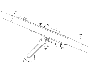
As illustrated in Figures 14, 18 and 19, the sleeve 74 is mounted so as to
slide in direction F along
a first toothed rail 80 on the pole 54. A latch 82, pivotally mounted on the
sleeve 74 engages a pawl
(not shown) with the teeth 80A on the rail 80. The pawl is spring biased so as
to engage the teeth 80A
on rail 80 to releasably lock the longtudinal position of the sleeve 74 along
the pole 54. A lever 82A on
the latch 82, when depressed against the sleeve 74, releases the pawl from
engaging the teeth 80A,
thereby releasing the sleeve 74 to slide along the pole 54.
A second toothed rail 84 is mounted on the opposite side of the pole 54 from
the first toothed
rail 80 as shown in Figure 18. A partially toothed gear 86 is mounted at the
base end 88A of a lever
handle 88. Lever handle 88 is pivotally mounted onto, so as to be carried on,
sleeve 74. Teeth 86A on
gear 86 engage against and along the teeth 84A of second toothed rail 84 when
engaged by the rotation
about axis G of a lever handle 88 (see Figure 20). The lever handle 88 is
normally biased away from pole
54 in a direction opposite to direction H by a spring 90 into a non-engaged
position, wherein the teeth
86A on gear 86 at the base end 88A of the lever handle 88 are disengaged from
the teeth 84A on the
second toothed rail 84. This is accomplished by using a short array of teeth
86A on gear 86. The short
array of teeth 86A only engage the teeth 84A on the second toothed rail 84
when the lever handle 88
has been rotated towards sleeve 74 and pole 54 in direction H, about its axis
of rotation G, which
coincides with the centroidal axis of rotation of gear 86, against the return
biasing force of spring 90.
Lever handle 88 is seen in its resting, non-actuating position in Figures 14,
15 and 18.
Once the lever handle 88 has been rotated in direction H sufficiently, so as
to engage the short
array of teeth 86A on gear 86 engage the teeth 84A of the second toothed rail
84, further rotation of the
CA 3042350 2019-05-06
lever handle 88 drives the sleeve 74 in direction F so as to translate the
sleeve 74 further down the pole
54 towards its handle end 44A thereby drawing the rod 76 and its connected
shuttle 78 and hook 58A
with it. This sliding in direction F of the sleeve 74, rod 76, and hook 58A
pulls the hook 58A a short
distance into bore 56A of head 56 sufficient to unlock the clutch formed of
first and second locking
members 28, 30 (hereinafter, collectively referred to as clutch 28, 30) in the
grounding clamp assembly
when the hook 58A is engaged in the eye 32 of the clutch release mechanism.
In use, the grounding clamp assembly 10 is first coupled to the head 56 of the
hot-stick 44. To
do this, the hook 58A, when the shuttle 78 is extended from the head bore 56A,
is hooked through the
eye 32 of the clutch release mechanism. The sleeve 74 is then slid by the
lineman down the pole 54 in
direction F with the ratchet lever 82A depressed until the shuttle 78 retracts
completely into the head
bore 56A. This causes the hook 58A to rotate in direction I into its locked
position. Drawing the hook
58A down into the bore 56A in the head 56 thereby also pulls the eye 32 of the
clutch release
mechanism down into the bore 56A of the head 56, until the base 42 of the
spring housing 34 on the
grounding clamp assembly 10 seats down snugly against the face 56B of the head
56. This completes the
coupling of grounding clamp 10 onto hot-stick 44.
At this point, the lineman releases the spring loaded latch lever 82A, thereby
engaging the latch
pawl (not shown) with the teeth 80A of the first toothed rail 80, locking the
position of the sleeve 74
along the pole 12. The clutch 28, 30 in the grounding clamp assembly 10
remains locked until a
significant tension force is subsequently applied to pull the eye 32 of the
clutch release mechanism
further into the bore 56A of the head 56 by a sufficient distance so as to
unlock and release the clutch
28, 30. In the case of a toothed clutch 28A, 30A, such as seen by way of
example in Figure 4A, this
further distance the eye 32 must be pulled may be, for example, 1/8 inch,
sufficient to release the
interlocking opposed-facing crown gear teeth 46, 48 of the clutch 28A, 30A. To
move the crown gear
teeth 46, 48 apart by this short distance, the lineman rotates the lever
handle 88 on the sleeve 74 in
direction H to engage the array of teeth 86A in a corresponding sector of gear
86 in the manner of a
pinion against and along a correspondingly short distance along the second
toothed rail 84. The spring
strength of spring 40 of the clutch release mechanism resisting the movement
of the eye 32 into the
head bore 56A upon actuation of the lever handle 88 may be in the order of 100
pounds-force (100 lbf).
The required force to compress spring 40 is sufficiently high enough such that
manual pulling of the eye
32 by hand by the lineman, so as to release the clutch 28A, 30A, is impossible
without the aid of a tool.
Using the lever handle 88, the lineman exerts the required pulling force on
the eye 32 (for example, 100
16
CA 3042350 2019-05-06
lbf) so as to overcome the spring strength of spring 40, collapsing the spring
40 and unlocking the clutch
28A, 30A.
With the clutch 28, 30 unlocked, the lineman may then twist the pole 54 about
its longitudinal
axis in direction D to open or close the clamp 10 so as to release or capture
a conductor 20 in the
capture cavity 18A of the clamp. The twisting of the pole 54 by the lineman is
done while maintaining
pressure on the lever handle 88 in direction H while lever handle 88 is in its
clutch release position, such
as illustrated in Figures 20 - 21. In the preferred embodiment illustrated,
the lever handle 88, when in
the clutch release position, is almost flush along the sleeve 74 so that
grasping of both the sleeve 74 and
the lever handle 88 may be done with one hand.
The lever handle 88 is, in a preferred embodiment, not completely flush
against sleeve 74, but
rather is inclined away from being flush along the sleeve by a small angle
beta (13). The remaining travel
of the lever handle 88, so as to position it flush against the sleeve 74, may,
in an embodiment, release
the short array of teeth 86A in the corresponding sector of gear 86 forming
the pinion on the end 88A of
the lever handle 88 from engagement within the teeth 84A on the second toothed
rail 84, thereby
disengaging the force acting on the sleeve 74 and allowing the clutch 28, 30
to relock under the force of
spring 40 as the pulling force on the eye 32 is removed. This removes the
corresponding large resistive
force of the latch 82 on the sleeve 74 acting on the first toothed rail 80.
Without removing this force,
releasing the ratchet on latch 82 may be difficult.
When the clutch 28, 30 is released, a lineman wishing to capture a conductor
20 within a
grounding clamp mounted to the head 56 of hot-stick 44, such as for example
the embodiment of the
ground clamp 100 illustrated in Figures 10 - 13 and 22, may now do so. With
the clamp 100 open, the
lineman seats the conductor 20 against the fixed jaw 102 on the clamp body
108, and then twists the
pole 54 in a first direction (direction D) about the pole's longitudinal axis
so as to rotate a threaded shaft
36 threadably journaled in a threaded bore in the clamp body 108. Rotation of
the threaded shaft 36
drives the threaded shaft through the bore so as to push against the arm 106
of a pivoting (i.e. movable)
jaw 104, pivotally mounted on the clamp body 108. Pushing against the arm 106
rotates the pivoting
jaw 104 about axis of rotation R, thereby closing the pivoting jaw 104 against
the conductor and
clamping the conductor between the fixed and pivoting jaws 102, 104
respectively. The procedure
described above is not limited to utilizing the embodiment of the ground clamp
100, and the above
procedure may also be carried out with any of the other embodiments of the
ground clamp disclosed
herein.
17
CA 3042350 2019-05-06
As will be apparent to those skilled in the art in the light of the foregoing
disclosure, many
alterations and modifications are possible in the practice of this invention
without departing from the
spirit or scope thereof. Accordingly, the scope of the invention is to be
construed in accordance with the
substance defined by the following claims.
18
CA 3042350 2019-05-06