Note: Descriptions are shown in the official language in which they were submitted.
CA 03042571 2019-05-02
WO 2018/0S2985 PCT/EP2017/077299
USER EQUIPMENT, BASE STATION, WIRELESS COMMUNICATION NETWORK,
DATA SIGNAL AND METHOD TO PROVIDE ENHANCED SPS CONTROL AND
CONTINUOUS SPS AFTER HANDOVER
Description
The present invention concerns the field of wireless communication networks or
systems,
more specifically, wireless communication networks in which a user equipment
is
configured with semi-persistent scheduling (SPS). A first aspect of the
inventive approach
provides for continuous or non-interrupted SPS of the user equipment after a
handover. A
second aspect of the inventive approach provides an enhanced control signaling
for a
user equipment configured with SPS to reduce the signaling overhead.
Fig. 1 is a schematic representation of an example of a network
infrastructure, such as a
wireless communication network or wireless communication system, including a
plurality
of base stations eN131 to eNB5, each serving a specific area surrounding the
base station
schematically represented by the respective cells 1001 to 1005. The base
stations are
provided to serve users within a cell. A user may be a stationary device or a
mobile
device. Further, the wireless communication system may be accessed by loT
devices
which connect to a base station or to a user. loT devices may include physical
devices,
vehicles, buildings and other items having embedded therein electronics,
software,
sensors, actuators, or the like as well as network connectivity that enable
these devices to
collect and exchange data across an existing network infrastructure. Fig, 1
shows an
exemplary view of only five cells, however, the wireless communication system
may
include more such cells. Fig. 1 shows two users UE1 and UE2, also referred to
as user
equipment (UE), that are in cell 1002 and that are served by base station
eNB2. Another
user UE3 is shown in cell 1004 which is served by base station eNB4. The
arrows 1021,
1022 and 1023 schematically represent uplink/downlink connections for
transmitting data
from a user UE1, UE2 and UE3 to the base stations eNB2, eNB4 or for
transmitting data
from the base stations eNB2, eNB4 to the users UE1, UE2, UE3. Further, Fig. 1
shows two
loT devices 1041 and 1042 in cell 1004, which may be stationary or mobile
devices. The
loT device 1041 accesses the wireless communication system via the base
station eNB4
to receive and transmit data as schematically represented by arrow 1061. The
loT device
1042 accesses the wireless communication system via the user UE3 as is
schematically
represented by arrow 1062.
CA 03042571 2019-05-32
WO 2018/082985 PCT/EP2017/077299
2
The wireless communication system may be any single-tone or multicarrier
system based
on frequency-division multiplexing, like the orthogonal frequency-division
multiplexing
(OFDM) system, the orthogonal frequency-division multiple access (OFDMA)
system
defined by the LTE standard, or any other IFFT-based signal with or without
CP, e.g. DFT-
s-OFDM. Other waveforms, like non-orthogonal waveforms for multiple access,
e.g. filter-
bank multicarrier (FBMC), generalized frequency division multiplexing (GFDM)
or
universal filtered multi carrier (UFMC), may be used.
For data transmission a physical resource grid may be uses, as defined, e.g.,
by the LTE
standard. The physical resource grid may comprise a set of resource elements
to which
various physical channels and physical signals are mapped. For example, in
accordance
with the LTE standard, the physical channels may include the physical downlink
shared
channel (PDSCH) carrying user specific data, also referred to as downlink
payload data,
the physical broadcast channel (PBCH) carrying for example the master
information block,
the physical downlink control channel (PDCCH) carrying for example the
downlink control
information (DCI), etc. The physical signals may comprise reference signals
(RS),
synchronization signals and the like. The LTE resource grid comprises a 10
milliseconds
frame in the time domain having a given bandwidth in the frequency domain. The
frame
has 10 subframes of 1 millisecond length, and each subframe includes two slots
of 6 or 7
OFDM symbols depending on the cyclic prefix (CP) length. The PDCCH may be
defined
by a pre-defined number of OFDM symbols per slot. For example, the resource
elements
of the first three symbols may be mapped to the PDCCH, i.e.. the size of the
PDCCH is
limited. Consequently, the number of also limits how many DCIs is limited that
may be
carried in one subframe. This may, in turn, limit the number of UEs which may
receive an
allocation for the subframe when using dynamic scheduling.
Fig. 2 shows an example of a LTE OFDMA-based subframe with two antenna ports
for
different selected Tx antenna ports. The subframe includes two resource blocks
(RB)
each made up of one slot of the subframe and 12 subcarriers in the frequency
domain.
The subcarriers in the frequency domain are shown as subcarrier 0 to
subcarrier 11, and
in the time domain, each slot includes 7 OFDM symbols, e.g. in the slot 0 OFDM
symbols
0 to 6 and in slot 1 OFDM symbols 7 to 13. A resource element is made up of
one symbol
in the time domain and one subcarrier in the frequency domain. The white boxes
10
represent resource elements allocated to the PDSCH carrying the payload or
user data,
also referred to a payload region. The resource elements for the physical
control channels
CA 03042571 2019-05-02
WO 2018/082985 PCT/EP2017/077299
3
(carrying non-payload or non-user data), also referred to the control region,
are
represented by the hatched boxes 12. In accordance with examples, resource
elements
12 may be allocated to the PDCCH, to the physical control format indicator
channel
(PCFICH). and to the physical hybrid ARQ indicator channel (PHICH). The cross-
hatched
boxes 14 represent resource elements which are allocated to the RS that may be
used for
the channel estimation. The black boxes 16 represent unused resources in the
current
antenna port that may correspond to RSs in another antenna port.
The resource elements 12, 14, 16 allocated to the physical control channels
and to the
physical reference signals are not evenly distributed over time. More
specifically, in slot 0
of the subframe the resource elements associated with the symbol 0 and the
symbol 1 are
allocated to the physical control channels or to the physical reference
signals, no resource
elements in the symbols 0 and 1 are allocated to payload data, The resource
elements
associated with symbol 4 in slot 0 as well as the resource elements associated
with
symbols 7 and 11 in slot 1 of the subframe are allocated in part to the
physical control
channels or to the physical reference signals. The white resource elements
shown in Fig.
2 may carry symbols associated with payload data or user data and in the slot
0 for
symbols 2, 3, 5 and 6, all resource elements 10 may be allocated to payload
data, while
less resource elements 10 are allocated to payload data in symbol 4 of slot 0,
and no
resource element is allocated to payload data in symbols 0 and 1. In slot 1
the resource
elements associated with symbols 8, 9, 10, 12 and 13 are all allocated to
payload data
while for symbols 7 and 11 less resource elements are allocated to payload
data.
The duration of the subframe is 1 millisecond, and in accordance with the LTE
standard,
the TTI is 1 millisecond. When transmitting data using the resource grid
structure shown in
Fig. 2, the receiver, for example the mobile terminal or mobile user, receives
the resource
elements depicted in Fig. 2 in 1 millisecond. The information contained or
defined by the
resource elements may be processed, and for each transmission, i.e., for each
TTI having
the 1 millisecond length, a constant number of payload data is received. The
transmission
scheme leads to an end-to-end latency of more than 1 millisecond, as the
receiver first
receives a transmission having a duration of 1 millisecond and then, once the
transmission is completed, processes the control information to see whether
some data
has been sent to the receiver, and in case it is true, the receiver decodes
the data channel
of a length of 1 millisecond. Thus, the duration of the transmission and the
processing
time add up to a period exceeding 1 millisecond.
CA 03042571 2019-05-02
WO 2018/082985 PCT/EP2017/077299
4
As explained above, the PDCCH is defined by a pre-defined number of OFDM
symbols,
i.e., there the size the PDCCH is limited which, consequently, also limits how
many DCIs
may be carried in one subframe having a length of 1 millisecond. This may, in
turn, limit
the number of UEs which may receive an allocation for the subframe when using
dynamic
scheduling. To support more allocations, without increasing the size of the
PDCCH, semi-
persistent scheduling (SPS) may be used. When using SPS, the UE is pre-
configured by
the transmitter or base station with a SPS C-RNTI (radio network temporary
identifier),
also be referred to as an allocation ID, and a periodicity. Once pre-
configured, the UE may
receive a further message defining an allocation for a downlink and/or uplink
transmission
of data on the basis of the associated SPS C-RNTI. This allocation will repeat
according
to the pre-configured periodicity (SPS interval). In other words, once
allocated, the
resources may be repeatedly used for receiving/transmitting data by the UE
without the
need to perform scheduling in each subframe. In case the radio link conditions
change,
the base station may provide to the UE a resource allocation message for re-
allocating
resources.
The SPS scheme is described, for example, in references [1] and [2]. SPS is a
combination of persistent and dynamic scheduling. The persistent scheduling is
used for
the allocation of periodic resources intended for a transmission of transport
blocks, and
the dynamic scheduling is used for potentially needed incremental redundancy,
i.e. hybrid
automatic repeat request (HARQ) retransmissions. SPS allows for the reduction
of control
information overhead that originates, for example, from signaling the downlink
(DL) and
uplink (UL) resource allocation patterns at times where a connection needs to
transfer
data. SPS may be used both for the DL and UL of both FDD (frequency division
duplexing) and TDD (time division duplexing). Reference [3] describes the
initial
configuration and the following activation/release of SPS. The base station
may configure
the UE to perform SPS at any time. Typically, this is done at the time of the
dedicated
bearer establishment for the service by RRC (radio resource control). The SPS
may be
configured/re-configured by RRC at any time using a configuration message that
is also
referred to as "SPS-Config". The SPS-Config message may include the SPS C-RNTI
as
well as configuration information for the downlink and for the uplink. The
configuration
message does not allow a UE to start the SPS, rather, the base station serving
the UE
has to explicitly activate SPS so as to allow the UE to use SPS
grants/assignments.
Once the UE has received the SPS-Config message including the SPS C-RNTI
associated with the UE. the UE may be configured by higher layers to decode
the PDCCH
5
with CRC (cyclic redundancy check) scrambled by the SPS C-RNTI in every
subframe, as
the eNB may activate/release SPS at any time using a DCI message. A SPS
activation/release message is validated by the UE,
After a valid activation, the UE decodes the PDCCH for CRC scrambled by the
SPS C-
RNTI to check for SPS-validated DCI control information in every SPS subframe,
Le., in
every subframe as defined by the SPS interval, the UE looks for information
regarding
possible changes, e.g. changes in the assigned resources, in the transmission
mode, the
MCS (modulation and coding scheme) or the like. The assignment of the resource
blocks
within the subframe is subject to the choice of the base station, and in case
the UE does
not receive any SPS-validated DCI, the resource block assignment and the other
transmission parameters, like transmission mode and MCS, remain as currently
configured, thereby avoiding a control signaling overhead.
SPS is used for services with periodic resource demands, and different
applications may
require different arrival times of transport blocks which may be configured by
the SPS
interval parameters. For example, Voice over IF (VolP) is an application where
data
arrives in periodic bursts of 20 milliseconds. Beyond that, as mentioned
above, there are
mission-critical and latency-constrained communications services; for example,
URLLC
(ultra reliable low latency communication) services, such as in machine-type
communication and in vehicular communication, which require pre-configured
resources
in shorter periods of time; for example, in periods of below 10 milliseconds
down to the
micro-second level and below. Applying SPS to such applications or services
leads to the
least possible signaling overhead when compared to frequent dynamic
configuration
updates, and embodiments of the present invention address SPS for such latency-
constrained applications.
Further, for the aforementioned latency-constrained applications, but also for
conventional
applications, respective services and higher OSI layers, such as on the
Application Layer,
as well as rate-controlled protocols on the Network Layer (for example, TCP),
may gain
performance in terms of network throughput, adaption latency or RTT (round
trip time)
reduction if SPS may be directly influenced and/or adapted by the application,
service or
protocol.
Fig. 3 shows an example of a conventional SPS configuration provided by RRG
(see
reference [5]). The configuration parameters "semi-persistentschedintervaIDL"
and "semi-
Date Recue/Date Received 2020-09-16
CA 03042571 2019-05-02
WO 2018/082985 PCT/EP2017/077299
6
persistentschedintervalUL" are based on a 4-bit field indicating an
enumeration of 16
different modes for the SPS intervals, also referred to as SPS periods. From
the 16
configurable modes, there is a selection of 10 predefined periods which are
labeled sfN
for a scheduling period of N subframes, with N 10. Further, 6 dynamically
adjustable
periods labeled spareX are provided. The base station provides the user
equipment with
an additional SPS-Config mode, using, for example, an RRC connection set up
message,
an RRC connection reconfiguration message or an RRC connection re-
establishment
message, as is outlined in reference [1]. The general dependency of the
intervals or
periods on the basis of multiples of a subframe, as defined in reference [2],
i.e., the
dependency on several milliseconds, is also valid for the spareX
configurations; however,
when using the spareX configuration, the SPS period may be lowered down to a
minimum
of 1 subframe (1 millisecond).
Thus, SPS may be used to reduce the control overhead for periodic
transmissions. SPS
may be for use cases such as voice over LTE, however, SPS is applicable to
many more
use cases which go together with different requirements as they may be
encountered,
e.g., in V2X (vehicle to everything) or V2V (vehicle to vehicle) scenarios.
Such specific
use cases may requre more complex SPS configurations, including nested SPS
configurat.ons. For example, V2V and V2X scenarios involve a high speed
movement of
the use equipment so that cell handovers may happen quite frequently.
Currently, all SPS
configuratons are lost on handover, i.e., when a user equipment moves from one
cell to
another cell of the wireless communication network so as to be no longer
served by the
currently responsible source base station but by a new target base station
which is also
referred to as a handover, the SPS configuration currently implemented in the
UE is no
longer maintained. This requires that the SPS configuration in the UE has to
be
reconfigured with the new or target base station.
In certain scenarios, such as the above mentioned V2X or V2V scenarios, the
user
equipment may be configured with more than one SPS configuration. For example,
up to
eight SPS configurations may be implemented in a user equipment in a V2X or a
V2V
scenario. Independent of the loss of the SPS configurations at handover, when
configuring the user equipment in a scenario with multiple SPS configurations,
additional
control messages are needed, such as the above mentioned DCI messages. For
each of
the SPS configurations one DCI message is needed to activate the respective
SPS
configuration and another DCI message is needed to initially allocate
resources for the
SPS configuration or to re-allocate resources for the respective SPS
configuration in case
CA 03042571 2019-05-02
WO 2018/082985 PCT/EP2017/077299
7
the channel quality changes. Thus, the increase in the number of SPS
configurations with
which a user equipment may be configured goes together with a corresponding
increase
in the number of control messages.
In accordance with a first aspect, it is an object of the present invention to
provide an
approach avoiding SPS reconfigurations within a UE after a handover, and in
accordance
with a second aspect, it is an object of the present invention to reduce
control signaling
overhead for UEs being configured with one or more configurations.
This object is achieved by the subject matter as defined in the independent
claims.
Embodiments are defined in the dependent claims.
Embodiments of the present invention are now described in further detail with
reference to
the accompanying drawings, in which:
Fig. 1 shows a schematic representation of an example of a wireless
communication
system;
Fig. 2 shows an example of an OFDMA-subframe for two antennas ports as
it may
be used for a conventional LTE downlink communication;
Fig. 3 shows an example of a conventional SPS configuration;
Fig. 4 shows a part of a wireless communication network similar to the
one
described above with reference to Fig. 1;
Fig. 5 shows a scenario similar to the one in Fig. 4 except that a base
station is
provided for a plurality of cells;
Fig. 6 is a schematic representation showing how the SPS synchronization
is kept
during handover in accordance with an embodiment;
CA 03042571 2019-05-02
WO 2018/082985 PCT/EP2017/077299
8
Fig. 7 shows an embodiment of a modified RRC message used to update the
SPS
C-RNTI in accordance with embodiments of the present invention;
Fig. 8 shows an embodiment of a modified SPS configuration message
including a
Keep on Handover flag; and
Fig. 9 shows a schematic representation of a SPS DCI message 200
including a
number of fields for controlling the UE being configured with SPS using a
single SPS configuration;
Fig. 10 shows a further embodiment of the second aspect of the inventive
approach in
accordance with which it is assumed that a user equipment is scheduled with
SPS using a plurality of different SPS configurations;
Fig. 11 shows an embodiment of a DCI message to allocate resources to SPS
configurations 1 to 8 that may be used in a user equipment configured with
SPS;
Fig. 12 shows another embodiment of the second aspect of the inventive
approach in
accordance with which it is assumed, again, that the user equipment is
configured with SPS using up to eight SPS configurations 1 to 8 and each of
the SPS configurations includes a specific SPS interval and a specific data
size;
Fig. 13 an embodiment for assigning resources for several SPS
configurations using
one DCI message, as has been described above with reference to Fig. 11 or
Fig. 12;
Fig. 14 illustrates another embodiment of the second aspect of the
inventive approach
providing for a dynamic assignment of resources to respective SPS
configurations;
Fig. 15 shows another embodiment of the second aspect of the present
invention in
which a number of SPS configurations are combined into a group; and
9
Fig. 16 is a schematic representation of a wireless communication system
for
transmitting information from a transmitter to a receiver.
In the following, preferred embodiments of the present invention are described
in further
detail with reference to the enclosed drawings in which elements having the
same or
similar function are referenced by the same reference signs.
Embodiments of a first aspect of the inventive approach will now he described.
In
.. accordance with the first aspect, the present invention provides for
continuous or non-
interrupted SPS of the user equipment after a handover.
Fig. 4 shows a part of a wireless communication network similar to the one
described
above with reference to Fig. 1. Three cells 1001 to 1003 are shown. Each cell
1001 to 1003
includes a base station eNBi to eNB3. The core network 108 of the wireless
communication network is schematically represented which includes the mobile
management entity (MME) 110. The base stations eNBi to eNB3 are connected to
the
core network 108 via the Si interface. Further, the base stations eNB, to eNB3
are directly
connected with each other via the X2 interface. The UE is a mobile terminal
provided in an
automobile_ In other embodiments, the UE may by any kind of vehicular device.
The UE
includes an antenna ANTuE to receive/transmit a radio signal 112. Each of the
base
stations eNBi to eNB3 includes a respective antenna ANTeNsi to ANT.NB3 to
receive/transmit the radio signal 112. The UE is initially located in the cell
1001, also
referred to as the source cell. The base station eNBi associated with the
source cell 1001
.. serves the UE, i.e., the ue is connected to the wireless communication
network via the
base station eNBi to receive/transmit data in a downlink/uplink connection.
The UE may
be within an automobile or may be part of the automobile. The UE is assumed to
travel at
a high speed and as the UE travels it will eventually leave the source cell
1001. In
accordance with its moving trajectory 114, the UE will reach the cell 1002,
also referred to
as the target cell. When moving from the source cell 1 001 to the target cell
1002, a
handover will be performed so that the UE will be served by the target base
station eNB2
of the target cell 1002 following the handover. As the UF keeps on moving in
accordance
with the moving trajectory 114, it will eventually leave the cell 1002 which
is now the
source cell and enter into the new target cell 1003 so that another handover
occurs and
the UE, following the handover, will be served by the base station eNB3.
During a
handover procedure respective messages are exchanged between the UE, the
source
Date Recue/Date Received 2020-09-16
10
base station, the target base station and the MME 110 as well as the serving
gateway.
The handover may be triggered by the core network, e.g. the MME 110, or it may
be
triggered by the UE.
The UE may be configured with SPS. Currently SPS is cell-based, i.e., the UE
will be
configured by the base station eNBI with SPS. The base station eNBI issues one
or more
control messages, such as DCI messages to activate SPS and to allocate
resources in
accordance with the SPS configuration. SPS will be carried out as long as the
UE is within
the cell 1001. After the handover and once the UE reached the target cell 1002
to be
served by the base station eNB2, the UE is newly configured with SPS in the
target cell
1002. Also a new identifier for SPS control signaling, like the SPS C-RNTI in
a LTE
system, may be issued by the target base station eNB2. RNTI in general is an
identifier for
SPS control signaling which may be named differently in other environments.
For
example, in a V2X environment a new RNTI may be provided for up to eight SPS
configurations.
In accordance with the present invention, newly configuring the UE with SPS
following a
handover is avoided. The UE, when moving from the source cell 1001 to the
target cell
1002, e.g., when performing a handover, maintains the SPS. In accordance with
embodiments, it may only be necessary to re-activate the SPS by an activation
signal
from the target base station eNB2 without the need to provide a complete and
new
configuration of the UE by the target base station. In accordance with
embodiments also a
new identifier for SPS control signaling, like the SPS C-RNTI, is issued.
In accordance with further embodiments of the present invention, to maintain
SPS the
SPS configuration that was used, for example by the source base station eNB,
to
configure the UE with SPS, is forwarded to the target base station eNB2 upon
the
handover. For example, the X2 interface may be used to pass the SPS
configuration from
the source base station eNBi to the target base station eNB2. In other
embodiments, the
SPS configuration may be passed from the source base station eNBi to the
target base
station eNI32 via the core network using the S1 interfaces of the respective
base stations.
In yet other embodiments, the UE may directly transmit the SPS configurations
during the
handover procedure to the target eNB2. No new configuration or reconfiguration
of the
SPS is needed following the handover of the UE from the source cell 1001 to
the target
cell 1002, which is then the new source cell. The UE maintains the SPS
configuration and
the target base station eNB2 receives the SPS configuration implemented in the
UE and
Date Recue/Date Received 2020-09-16
CA 03042571 2019-05-02
WO 2018/082985 PCT/EP2017/077299
11
may continue with the SPS on the basis of the received SPS configuration. In
accordance
with embodiments, an activation signal may be sent out by the target base
station eNB2 to
indicate to the UE that SPS is continued. In accordance with other
embodiments, the
activation may occur responsive to a resource assignment for SPS by the target
base
.. station.
In accordance with embodiments, in addition to passing the SPS configuration
to the
target base station eNB2, the target base station may update the SPS C-RNTI
and inform
the UE accordingly, for example in a situation in which the SPS C-RNTI has
been used in
the source cell 1001 is occupied, blocked or otherwise used in the target cell
1002.
In Fig. 4, the UE is either within the automobile or is part of the
automobile. In accordance
with other embodiments, the UE may be another kind of mobile terminal, for
example a
handheld device or a sensor operating in accordance with the NB-10T standard.
The
.. sensor may be part of the automobile or it may be part of another moving
entity such as a
high speed train. The user of the UE may be a passenger within the vehicle
travelling on a
highway or the user may be a passenger in a high speed train or an airplane.
In such
scenarios, the UE will experience frequent handovers and, in accordance with
the
inventive approach, any reconfiguration of the SPS is avoided, as the UE
maintains the
one or more current SPS configurations, which may be transferred by the source
base
station to the target base station via the X2 interface or via the Si
interface. In accordance
with embodiments, the SN status transfer message may be used to transfer the
SPS
configuration(s). An example of a data structure including the SPS
configuration has been
described above with reference to Fig. 3.
Fig. 4 shows that a base station is provided for one cell. However, a base
station may also
be provided for a plurality of cells as is schematically shown in Fig. 5. Fig.
5 shows a
scenario similar to the one in Fig. 4 except that base station eNB2 is
provided for a
plurality of cells, namely cells 1002, 1003 and 1004. A UE within one of cells
1002, 1003 and
1004 will connect to the network via base station eNB2. When the UE moves,
e.g., from
the cell 1002 to the cell 1003 a handover will take place. Also in such a
scenario, SPS
needs to be newly configured when a handover occurs, despite the fact that the
base
station does not change. Newly configuring the UE with SPS following the
handover is
avoided. The UE, when moving from the source cell 1002 to the target cell
1003, i.e., when
performing a handover, maintains the SPS. Since the base station enB2 is aware
of the
SPS configuration, no transfer of the SPS configuration occurs in this
scenario. In this
CA 03042571 2019-05-02
WO 2018/082985 PCT/EP2017/077299
12
embodiment only a new identifier for SPS control signaling, like the SPS C-
RNTI, is
issued following the handover.
In accordance with further embodiments, transferring the SPS configuration
from the
source cell or the source base station to the target cell or target base
station further
includes signaling the time of the next expected SPS packet to the target base
station so
as to allow the target base station to continue with the SPS with the correct
timing. For
example, the time to the next SPS interval may be signaled towards the target
base
station. In accordance with other embodiments, the period of the SPS interval
which has
already been used up so far is signaled to the target base station or the
start of the next
SPS interval is signaled as an absolute time, for example on the basis of the
radio frame,
the subframe number, the slot number or the TTI (Transmission Time Interval)
number. In
accordance with embodiments, the time of the next expected SPS packet may be
signaled to the target base station either by the user equipment or by the
source base
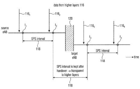
station. Fig. 6 is a schematic representation showing how the SPS
synchronization is kept
during handover in accordance with an embodiment. Fig. 6 illustrates a
downlink situation
in which a user equipment is initially served by a source base station and
data 116 from
higher layers in the network is to be transmitted to the user equipment. The
user
equipment is configured with SPS having a periodicity or SPS interval 118. For
example,
when data 1161 is received at the source base station, at a time t1, the data
1161 is
transmitted from the base station to the user equipment on the scheduled
resources. At a
later time, further data 1162 may be received at the base station which is
transmitted to
the user equipment at t2. The time difference between ti and t2 is the SPS
interval 118.
Fig. 6 schematically represents the handover at 120, and following the
handover 120, the
user equipment is no longer served by the source base station but is now
served by the
target base station. The target base station receives information about the
SPS
configuration of the UE and about the time to the next expected SPS packet so
that data
1163 for the user equipment may be transmitted by the target base station at
the time t3.
Further data 1164 may be transmitted from the target base station to the user
equipment
at the time t4. The respective times ti to t4 are separated by the SPS
interval 118 which is
defined in the SPS configuration of the user equipment. The SPS interval is
kept also after
the handover as the time to the next SPS transmission t3 is signaled to the
target base
station either by the user equipment or by the source base station. This
process is
transparent for the higher layers of the system so that a continuous SPS even
in case of a
handover is enabled.
CA 03042571 2019-05-02
WO 2018/082985 PCT/EP2017/077299
13
In accordance with further embodiments, the UE may inform the target base
station about
the SPS configuration and the SPS C-RNTI using an uplink control or data
channel and
the source base station may send an indication of the UE or a list of UEs to
the target
base station indicating if specific information will be included in the
control or data
.. channel. For example, when the X2 interface or the handover context
transfer is not
available, the UE may inform the target eNB on their SPS configuration through
the UL
control or data channel. The UE may use RRC signaling to transmit its SPS
configuration
and/or the time to the next SPS occurrence to the target eNB after the
handover with the
request to continue the same SPS configuration. This request may be
acknowledged by
.. the target eNB by directly activating the SPS via DCI or via RRC signaling.
In accordance with further embodiments, when the handover occurs, in the
handover
region, a dual connectivity of the UE may be provided. The UE may be connected
to the
source and target base stations which may help leverage a reconfiguration
duration for
time critical applications. SPS configuration updates may be triggered by the
target base
station through the X2 interface, for example for signaling the new SPS C-RNTI
to the UE,
and the source base station may act as the transmitter of the update message.
In other
words, the dual connectivity mode, in which the UE maintains dual connectivity
to the
source and target base stations, allows handling a situation in which the SPS
C-RNTI of
the source cell cannot be used in the target cell, and the target base station
may already
generate an update of the SPS configuration indicating also the C-RNTI to be
used. The
update is then performed by the source base station by transmitting the
updated SPS
configuraton to the UE being in the handover region.
As mentioned above, in accordance with embodiments, in a situation in which
the target
cell 1002 in Fig. 4 does not allow using the same SPS C-RNTI as used by the
source cell
1001, for example because the SPS C-RNTI is used for another UE in the target
cell,
either the source base station or the target base station may update the SPS C-
RNTI for
the UE, for example using RRC (radio resource control) signaling. This
signaling may
include a RRC connection reconfiguration message that is issued by the source
base
station eNBi to reconfigure the UE so that the SPS C-RNTI, upon the handover,
is
updated with the new SPS C-RNTI to be used in the target cell. In accordance
with other
embodiments, the SPS C-RNTI may be updated by the target base station, also by
an
RRC signaling, once the handover is completed.
CA 03042571 2019-05-02
WO 2(118/(182985 PCT/EP2017/077299
14
In Fig. 4, it has been assumed that all base stations are macro base stations
of the
wireless communication network. However, in accordance with other embodiments,
the
respective base stations may all be small cell base stations, such as femto
base stations,
being deployed within a macro cell of the wireless communication network. in
accordance
with other embodiments, the base stations may include macro cell base stations
and small
cell base stations.
In accordance with other embodiments, the inventive approach may also be
applied to
UEs which are not moving at a high speed, i.e., the inventive approach may
also be
applied to UEs which experience a handover less frequently than a fast moving
UE. Thus,
the inventive approach is not limited to fast travelling UEs.
In accordance with embodiments, the SPS C-RNTI for the UE may be updated using
an
RRC (radio resource control) signaling. This signaling may include a RRC
connection
reconfiguration message that is issued by the source base station to
reconfigure the UE
so that the SPS C-RNTI, upon the handover, is updated with the new SPS C-RNTI
to be
used in the target cell. In accordance with other embodiments, the SPS C-RNTI
may be
updated by the target base station, also by an RRC signaling, once the
handover is
completed. Fig. 7 shows an embodiment of a modified RRC message used to update
the
SPS C-RNTI in accordance with embodiments of the present invention. When
compared
to the SPS-configuration message depicted in Fig. 3, the RRC message to update
the
SPS C-RNTI is extended to include the entry "newSemiPersistSchedC-RNTI" 130,
the
entry "oldSemiPersistSchedC-RNTI" 132, the entry "update NULL" 134 and the
entry
"update NULL" 136. The RRC message as depicted in Fig 7 may be used by the
source
base station which may request a SPS-C-RNTI to be used in the target cell from
the target
base station, for example via the X2 interface. Prior to the handover or
reconnection of the
UE to the target cell, the update message may be issued. The source base
station
generates the update message and includes into entry 130 the new SPS C-RNTI
received
from the target base station, while the currently used SPS C-RNTI of the
source base
station is still indicated at entry 132 so that, despite the receipt of the
update, as the
entries 134 and 136 are still indicated as "null", the UE continues to use the
old or source
SPS C-RNTI. Once the handover is completed, the target base station may update
the
configuration by changing the entry 134 and 136 so that it is indicated that
now the new
SPS C-RNTI for the target cell 1002 is to be used. The SPS update message as
indicated
in Fig. 7 may be based on the SPS-Config RRC message as it is described in
reference
[7]. Fig. 7 shows at 138 schematically an embodiment in accordance with which
the above
described information about the time to the next SPS is included in the SPS
configuration.
CA 03042571 2019-05-02
WO 2018/082985 PCT/EP2017/077299
In accordance with other embodiments of the present invention, the UE which
maintains
its SPS configuration may be reactivated following a handover by the target
base station.
The initial SPS configuration may be modified to include a "Keep on Handover"
flag which,
5 when activated, causes the UE to wait for a certain time after the
handover for a
reactivation of SPS by the target base station and, in case no reactivation is
received, the
SPS is suspended. The reactivation may be a signal from the target base
station which
may include a new SPS C-RNTI. In case no new SPS C-RNTI is included, the
currently
used SPS C-RNTI is considered to be still valid and the UE keeps using this
SPS C-RNTI.
10 This may be done by a corresponding RRC signaling to change the SPS C-RNTI
or
directly by a DCI activation with the old RNTI or a new one, if assigned by
the source
eNB. When the SPS is not reactivated within this certain time, the UE releases
its SPS
configuration. Fig. 8 shows an embodiment of a modified SPS configuration
message,
more specifically a portion of the SPS configuration message for the downlink
and for the
15 .. uplink is shown including the additional entries 140 and 142 defining
the Keep on
Handover flag.
In the following, a second aspect of the present invention will be described
in further
detail. It is noted, that the second aspect described in the following, can be
used in
combination with the first aspect described above or it may be used
independent of the
first aspect. In accordance with the second aspect of the present invention,
the signaling
of control messages is reduced by providing a single control message or DCI
message to
the user equipment which is configured with SPS for the activation of a
resource allocation
of one or more SPS configurations, or for activating a plurality of SPS
configurations, or
for addressing a group of SPS configurations by a single DCI message. Instead
of using
separate DCI messages for activating the SPS in the user equipment and for the
resource
allocation or for reconfiguring the resource allocation in case of changing
channel
properties, in accordance with embodiments, initially, when the SPS is to be
started, the
user equipment receives a single DCI message which causes SPS to be activated
and
which may also include the resource allocation information. The second aspect
of the
present invention may also be used together with the above described first
aspect
providing for a continuous SPS in case of a handover.
In the following, embodiments of the inventive approach in accordance with the
second
aspect will be described in further detail. Fig. 9 shows a schematic
representation of a
SPS DCI message 200 including a number of fields for controlling the UE being
CA 03042571 2019-05-02
WO 2018/0S2985 PCT/EP2017/077299
16
configured with SPS using a single SPS configuration. In the embodiment of
Fig. 9, the
DCI message 200 includes information about the modulation and coding scheme
2001,
information about the resources 2002 to be allocated for the respective SPS
configuration
for which the DCI message is provided, and information 2003 which causes the
SPS in the
UE to be activated. Thus, one or a single DCI message 200 is used to activate
the SPS in
the user equipment and to allocate resources for the SPS configuration. Thus,
in
accordance with the embodiment described with reference to Fig. 9, signaling
overhead
for sending a plurality of DCI control messages, namely separate DCI control
messages to
activate and allocate resources is avoided as the activation and resource
allocation is
done in a single DCI message.
Fig. 10 shows a further embodiment of the second aspect of the inventive
approach in
accordance with which it is assumed that a user equipment is scheduled with
SPS using a
plurality of different SPS configurations, as it might be implemented in V2X
or V2V
scenarios. For example, plural SPS configurations may be used dependent on the
kind of
data to be transmitted so as to meet requirements of transmission intervals
which may be
different for data from different entities, for example, data regarding
specific information
about the state of the vehicle may require to be transmitted less frequently
than position
information about the vehicle. Also the size of the data to be transmitted may
be different.
For the different kinds of data to be transmitted or to be received at the
user equipment,
different SPS intervals and, therefore, different SPS configurations, may be
implemented
at the user equipment. Also a different number of resources may be required
for the
transmission. To reduce signaling overhead in such a scenario, in accordance
with the
embodiment depicted in Fig. 10 the SPS DCI message 202 is provided. It is
assumed that
the SPS DCI message 202 is for a user equipment being configured with SPS
using eight
different SPS configurations. The SPS DCI message 202 includes information
2021 which
causes SPS configurations to be activated upon receipt of the DCI message at
the user
equipment. The SPS DCI message 202 may be used to activate all of the SPS
configurations or it may be used to activate a subset or a group of the SPS
configurations.
In the latter case, the SPS DCI message 202 includes the optional information
2022
identifying those SPS configurations or a group of SPS configurations (see
also the
embodiment described below with reference to Fig. 15) to be activated upon
receipt of the
DCI message at the user equipment. The SPS configurations or the group SPS
configurations may have associated therewith respective identifiers, also
referred to as
SPS-IDs, and for those SPS configurations to be activated, the field 2022
includes the
corresponding SPS-IDs. When only activating the SPS configurations no
additional
CA 03042571 2019-05-02
WO 2018/0S2985 PCT/EP2017/077299
17
information concerning the modulation and coding scheme may be needed. Thus,
in
accordance with the embodiment of Fig. 10, only one DCI message or a single
DCI
message is used to activate all or a subset of the SPS configurations with
which a user
equipment may be configured, thereby reducing the signaling overhead to a
single DCI
message rather than sending up to eight different DCI messages for activating
each of the
SPS configurations individually. The DCI message 202 does not cause any
resource
allocation, this may be done by a separate DCI message sent at a later time.
This later
DCI message may be an individual message for each of the SPS configurations or
it may
be a combined SPS DCI indicating the resources for all or the subset of
activated SPS
configurations with which the user equipment is configured.
Fig. 11 shows an embodiment of a DCI message to allocate resources to all or a
subset of
SPS configurations 1 to 8 that may be used in a user equipment configured with
SPS. The
SPS DCI message 204 is provided which includes information 2041 about the
modulation
and coding scheme. The SPS DCI message 204 includes information 2042 about
resources to be allocated for the SPS configurations, e.g., dependent on the
data size
defined by the SPS configuration. The SPS DCI message 204 may be used to
allocate the
resources for all of the SPS configurations or it may be used to allocate the
resources for
a subset or a group of the SPS configurations. In the latter case, the SPS DCI
message
204 includes the optional information 2043 identifying those SPS
configurations or a group
of SPS configurations (see also the embodiment described below with reference
to
Fig. 15) for which resources are to be allocated upon receipt of the DCI
message at the
user equipment. The SPS configurations or the group SPS configurations may
have
associated therewith respective identifiers, also referred to as SPS-IDs, and
for those SPS
configurations for which resources are to be alfocated, the field 2043
includes the
corresponding SPS-IDs. In the embodiment of Fig. 11, it is assumed that up to
eight SPS
configurations are configured in the UE, and the DCI message 204 signals in
field 2042 for
all or each addressed SPS configuration the respective resources to be
allocated. For
example, a first set of resources or resource elements may be assigned to the
SPS
configuration 1, and the following resource elements are allocated to SPS
configurations 2
to 8. This is schematically represented on the right hand side of Fig. 11
showing the
subframe and the DCI message 2004 that is transmitted in the PDCCH and
includes the
resource information 2042 which, as is schematically indicated in the
subframe, points to
the respective resource elements. Thus, in accordance with the embodiment of
Fig. 11,
one DCI message or a single DCI message is used to allocate the resources for
all or a
subset of the SPS configurations 1 to 8.
CA 03042571 2019-05-02
WO 2018/082985 PCT/EP2017/077299
18
Fig. 12 shows another embodiment of the second aspect of the inventive
approach in
accordance with which it is assumed, again, that the user equipment is
configured with
SPS using up to eight SPS configurations 1 to 8 and each of the SPS
configurations
includes a specific SPS interval and a specific data size. The embodiment of
Fig. 12
combines the above described embodiments of Fig. 10 and Fig. 11 in that the
DCI
message 206 activates and allocates resources for all or a subset of the SPS
configurations 1 to 8. The DCI message 206 includes the information about the
modulation and coding scheme 2061 to be used and, as necessary, further
control
information. The SPS DCI message 206 includes information 2062 which causes
SPS
configurations to be activated upon receipt of the DCI message at the user
equipment,
and information 2063 about resources to be allocated for the SPS
configurations, e.g.,
dependent on the data size defined by the SPS configuration. The SPS DCI
message 206
may be used to activate and allocate the and resources for all of the SPS
configurations
or it may be used to activate and allocate the resources for a subset or a
group of the SPS
configurations. In the latter case, the SPS DCI message 206 includes the
optional
information 2064 identifying those SPS configurations or a group of SPS
configurations
(see also the embodiment described below with reference to Fig. 15) to be
activated and
for which resources are to be allocated upon receipt of the DCI message at the
user
equipment. The SPS configurations or the group SPS configurations may have
associated
therewith respective identifiers, also referred to as SPS-IDs, and for those
SPS
configurations which are activated and for which resources are allocated, the
field 2064
includes the corresponding SPS-IDs. Thus, in the embodiment of Fig. 12, one
DCI
message or a single DCI message is used to activate and allocate resources for
one or
more of the SPS configurations 1 to 8. As described above with reference to
Fig. 11, the
DCI is transmitted in the PDCCH of the subframe and the resource allocation is
schematically represented at 2064 in the right hand side of Fig. 12.
The above described embodiments of the second aspect are not limited to user
equipments operated in V2V or V2X scenarios but may apply to any kind of user
equpment including one or more SPS configurations to be used.
The embodiments described above reference to Fig. 9 to Fig. 12 allow for a
significant
reduction of control message signaling thereby reducing the control message
signaling
overhead. The above described approach regarding the use of one DCI message
for
activating and/or allocating resources for one or more SPS configurations may
be used
CA 03042571 2019-05-02
WO 2018/082985 PCT/EP2017/077299
19
either for the downlink configuration or for the uplink configuration. In
accordance with
further embodiments, a single DCI message may be used for configuring the
resources
and activating the SPS for both the uplink and downlink transmission of data.
Fig. 13 shows an embodiment for assigning resources for several SPS
configurations
using one DCI message, as has been described above with reference to Fig. 11
or
Fig. 12. Three SPS configurations SPS 1 to SPS 3 having different SPS time
intervals t1
to t3 and different data sizes x1 to x3 are shown. Further, each SPS
configuration has
associated therewith an identifier ID i1, i2, i3. The DCI message 204, 206
indicates at
2043 or 2064 the resources or a block of resources to be used for all SPS
configurations.
The block of resources to be assigned is schematically represented in Fig. 13
at 208. The
block 208 of resources may be formed by a plurality of resource elements of a
subframe
which may be continuous in time/frequency, or may be separate from each other.
In other
words, a continuous block of resource elements may be provided or a non-
continuous
block of resource elements may be provided, The resource elements of the
respective
block are allocated to the respective SPS configurations by the DCI message.
In the
embodiment of Fig. 13, the single DCI message 204, 206 assigns the resources
for all
SPS configurations SPS1 to SPS3 and, in case there are more SPS configurations
also for
the additional SPS configurations. The resources or the resource block 208 is
split using
the data size of each SPS configuration by assigning the resources from the
first to the
last configuration according to the identifier associated with the respective
SPS
configuration. Thus, as is shown in Fig. 13, a first set of resources or
resource elements is
allocated to the SPS configuration 1 having the identifier i1, and subsequent
resource
elements are allocated to the SPS configuration having the identifier i2. In
accordance
with other embodiments, the resource elements in the block 208 may be
allocated in a
different way, for example, the first resource elements may be assigned to one
of the
second or third SPS configurations, or resource elements which are non-
continuous may
be assigned to the same SPS configuration, for example, the SPS configuration
having
the ID i1 may have a first set of resource elements at the beginning of the
block 208
assigned thereto, and a further number of resource elements from another part
of the
block 208 which is non-continuous with the first block. The one or single DCI
may be used
to allocate or change resources for several configurations at once by
allocating the
amount of resources necessary for transmitting all configurations
simultaneously, by
defining the resources of resource block 208 and then causing an allocation of
the
resources from the block 208 at the user equipment in accordance with the
respective
configurations as described above.
CA 03042571 2019-05-02
WO 2018/0S2985 PCT/EP2017/077299
Fig. 14 illustrates another embodiment of the second aspect of the inventive
approach
providing for a dynamic assignment of resources to respective SPS
configurations.
Fig. 14, in a similar way to Fig. 13, shows three SPS configurations SPS1 to
SPS3 having
5 different SPS intervals, different data sizes and different IDs. On the
right side of Fig. 14,
the maximum resources to be assigned by a single DCI, such as DCI message 204,
206
described above with reference to Fig. 11 and Fig. 12, are shown as resource
block 208.
The resource block 208 may define a continuous or non-continuous number of
resource
elements to be allocated to the SPS configurations. When sending a DCI message
to
10 allocate resources, it may be determined that at the time t1 all three
SPS configurations
are used by the UE, and the resources provided by block 208 are distributed
among the
SPS configurations in accordance with the respective data sizes. At time t2,
it may be
determined that currently only the first SPS configuration is used so that not
all of the
allocated resources of the block 208 are needed for the SPS configurations. As
is shown
15 at time t2 only the resources for SPS configuration 1 are allocated, and
the other
resources of block 208 remain free. In accordance with embodiments, these free
resource
elements may be scheduled otherwise. For example, the free resource elements
may be
used by the same UE for non SPS traffic, or may be used by a different UE. At
time t3, it is
determined that the UE uses the second SPS configuration :n addition to the
first SPS
20 configuration, and the DCI now also allocates the resources for the
second srs
configuration. The number of free resources is smaller than at time t2. The
situation at time
t4 corresponds to the one at time t2, and the situation at time ts corresponds
to the
situation at time tl.
Thus, in accordance with the embodiment of Fig. 14, the resources that may be
needed
for the SPS configuration are allocated at the very beginning for each SPS
occurrence,
however, the number of resources actually used at a specific time is
determined
dependent on how many SPS configurations are currently scheduled and dependent
on
the size or data used by the respective SPS configuration in the UE.
Another embodiment of the second aspect of the present invention will now be
described
with reference to Fig. 15. A number of SPS configurations are combined into a
group.
Fig. 15 shows in the upper part an example in which a UE may be configured
with four
SPS configurations SPS1 to SPS4, each having assigned a SPS ID. The SPS
configurations may be controlled in accordance with the DCI messages described
above
with reference to Fig. 10 to Fig. 14. In accordance with the embodiment of
Fig. 15, all of
CA 03042571 2019-05-02
WO 2018/082985 PCT/EP2017/077299
21
SPS configurations or a subset of SPS configurations are combined into a
group. Fig. 15
shows a group having assigned thereto an ID which is used to address, within
the DCI
message, all members of the group, which includes SPS configurations SPS1,
SPS3 and
SPS4 as indicated by the respective IDs. When a DCI message is sent indicating
ID5, all
SPS configurations SPS1, SPS3 and SPS4 will be addressed, e.g., to be changed
or
modified. For example, when indicating in the respective ID fields 2022, 2042
and 2062 of
the DCI messages 202, 204, 206 the group ID, all SPS configurations in this
group will be
addressed. By using one or a single DCI message, groups of SPS configurations
may be
switched. For example. several SPS configurations may be changed using a
single DCI
message. Further, SPS configurations may be added or removed semi-statically
from the
group, and the DCI message having the corresponding group ID will change all
the
configurations in the group. In accordance with embodiments, adding/removing a
SPS
configuratlon to/from a group is caused not by a DCI message, but a further
control
message may be used that is received at the UE. For example, a RRC message may
be
used. In accordance with other embodiments, an implicit removal from a group
may occur.
when a SPS configuration (currently belonging to a group) is reconfigured on
its own with
a DCI.
Embodiments of the present invention may be implemented in a wireless
communication
system as depicted in Fig. 1 including base stations and UEs, like mobile
terminals or loT
devices. Fig. 16 is a schematic representation of a wireless communication
system for
communicating information between a base station BS and a UE. The base station
BS
includes one or more antennas ANTBs or an antenna array having a plurality of
antenna
elements. The UE includes one or more antennas ANTuE. As is indicated by the
arrow 300
signals are communicated between the base station BS and the UE via a wireless
communication link, like a radio link. The wireless communication system may
operate in
accordance with the techniques of the first aspect and the second aspect
described
herein.
For example, in accordance with the first aspect the UE is served by the base
station BS
which in this scenario is a source base station of a source cell of the
wireless
communication network. The wireless communication network includes a plurality
of cells,
and each cell has a base station. The UE receives via the one or more antennas
ANTuE a
radio signal including a SPS configuration message from the base station so
that the UE
is configured with semi-persistent scheduling in accordance with the SPS
configuration
provided by the source base station. The UE will maintain SPS when moving from
the
CA 03042571 2019-05-02
WO 2018/082985 PCT/EP2017/077299
22
source cell to a target cell of the wireless communication network. The UE
includes a
signal processor 302 to process the SPS configuration message and to maintain
SPS
after moving from the source cell to the target cell, e.g., following a
handover. The base
station BS, when operating as the source base station, serves the UE located
in the
source cell, and configures the UE with SPS in accordance with the SPS
configuration.
The base station BS comprises a signal processor 304 to generate a radio
signal to
transmit the SPS configuration to a target base station associated with a
target cell, when
the user equipment moves from the source cell to the target cell of the
wireless
communication network. The base station BS, when operating as the target base
station,
receives the SPS configuration from the source base station currently serving
the UE
configured with SPS in accordance with the SPS configuration. The SPS
configuration is
received when the UE moves from the source cell to the target cell. The base
station BS
comprises a signal processor 304 to process a received radio signal to obtain
the SPS
configuration transmitted by the source base station. Further, the signal
processor 304
generates a radio signal to serve the UE located in the target cell using SPS
in
accordance with the received SPS configuration.
For example, in accordance with an example of the second aspect, the user
equipment
UE is configured with SPS in accordance with a SPS configuration. The UE
receives via
the one or more antennas ANTuE a radio signal, which includes a control
message. The
UE includes a signal processor 302 to process the radio signal to obtain the
control
message which signals an activation of the SPS configuration and which signals
resources to be allocated for the SPS configuration. The base station BS
configures the
UE with SPS in accordance with the SPS configuration, e.g., by generating a
SPS
configuration message using the signal processor 304 and sending the SPS
configuration
message to the UE via the one or more antennas ANTBs. Further, the base
station
generates and transmits a radio signal to the UE, which includes a control
message. The
control message signals an activation of the SPS configuration and signals
resources to
be allocated for the SPS configuration.
In accordance with another example of the second aspect, the user equipment UE
is
configured with SPS in accordance with a plurality of SPS configurations. The
UE
receives via the one or more antennas ANTuE a radio signal, which includes a
control
message. The UE includes a signal processor 302 to process the radio signal to
obtain
the control message which signals an activation of the plurality of SPS
configurations. The
control message may also signal resources to be allocated for the plurality of
SPS
CA 03042571 2019-05-02
WO 2018/0S2985 PCT/EP2017/077299
23
configurations. The base station BS configures the UE with SPS in accordance
with the
plurality of SPS configurations, e.g., by generating one or more SPS
configuration
messages using the signal processor 304 and sending the one or more SPS
configuration
messages to the UE via the one or more antennas ANTBs. Further, the generates
and
transmits a radio signal to the UE, which includes a control message. The
control
message signals an activation of the plurality of SPS configurations. The
control message
may also signal resources to be allocated for the plurality of SPS
configurations.
In accordance with yet another example of the second aspect, the user
equipment UE is
configured with SPS in accordance with one or more groups of SPS
configurations, a
group of SPS configurations including two or more SPS configurations. The UE
receives
via the one or more antennas ANTuE a radio signal, which includes a control
message.
The UE includes a signal processor 302 to process the radio signal to obtain
the control
message which addresses the SPS configurations of one or more of the groups of
SPS
.. configurations. The base station BS configures the UE with SPS in
accordance with one
or more groups of SPS configurations, a group of SPS configurations including
two or
more SPS configurations, e.g., by generating one or more SPS configuration
messages
using the signal processor 304 and sending the one or more SPS configuration
messages
to the UE via the one or more antennas ANTBs. Further, the generates and
transmits a
radio signal to the LIE, which includes a control message. The control message
addresses
the SPS configurations of one or more of the groups of SPS configurations.
Although some aspects of the described concept have been described in the
context of an
apparatus, it is clear that these aspects also represent a description of the
corresponding
method, where a block or a device corresponds to a method step or a feature of
a method
step. Analogously, aspects described in the context of a method step also
represent a
description of a corresponding block or item or feature of a corresponding
apparatus.
.. Depending on certain implementation requirements, embodiments of the
invention may be
implemented in hardware or in software. The implementation may be performed
using a
digital storage medium, for example cloud storage, a floppy disk, a DVD, a
Blue-Ray, a
CD, a ROM, a PROM, an EPROM, an EEPROM or a FLASH memory, having
electronically readable control signals stored thereon, which cooperate (or
are capable of
.. cooperating) with a programmable computer system such that the respective
method is
performed. Therefore, the digital storage medium may be computer readable.
CA 03042571 2019-05-02
WO 2018/082985 PCT/EP2017/077299
24
Some embodiments according to the invention comprise a data carrier having
electronically readable control signals, which are capable of cooperating with
a
programmable computer system, such that one of the methods described herein is
performed.
Generally, embodiments of the present invention may be implemented as a
computer
program product with a program code, the program code being operative for
performing
one of the methods when the computer program product runs on a computer. The
program code may for example be stored on a machine readable carrier.
Other embodiments comprise the computer program for performing one of the
methods
described herein, stored on a machine readable carrier. In other words, an
embodiment of
the inventive method is, therefore, a computer program having a program code
for
performing one of the methods described herein, when the computer program runs
on a
computer.
A further embodiment of the inventive methods is, therefore, a data carrier
(or a digital
storage medium, or a computer-readable medium) comprising, recorded thereon,
the
computer program for performing one of the methods described herein. A further
embodiment of the inventive method is, therefore, a data stream or a sequence
of signals
representing the computer program for performing one of the methods described
herein
The data stream or the sequence of signals may for example be configured to be
transferred via a data communication connection, for example via the Internet.
A further
embodiment comprises a processing means, for example a computer, or a
programmable
logic device, configured to or adapted to perform one of the methods described
herein. A
further embodiment comprises a computer having installed thereon the computer
program
for performing one of the methods described herein.
In some embodiments, a programmable logic device (for example a field
programmable
gate array) may be used to perform some or all of the functionalities of the
methods
described herein. In some embodiments, a field programmable gate array may
cooperate
with a microprocessor in order to perform one of the methods described herein.
Generally.
the methods are preferably performed by any hardware apparatus.
25
Further embodiments are now described.
A 1st embodiment provides a user equipment (UE), wherein the user equipment
(UE) is
configured with semi-persistent scheduling (SPS) in accordance with a SPS
configuration,
and the user equipment (UE) is configured to receive and process a radio
signal, the radio
signal including a control message (DCI), and the control message (DCI) to
signal an
activation of the SPS configuration and to signal resources to be allocated
for the SPS
configuration.
A 2nd embodiment provides a user equipment (UE), wherein the user equipment
(UE) is
configured with semi-persistent scheduling (SPS) in accordance with a
plurality of SPS
configurations, and the user equipment (UE) is configured to receive and
process a radio
signal, the radio signal including a control message (DCI), and the control
message (DCI)
to signal an activation of the plurality of SPS configurations.
A 3rd embodiment provides the user equipment (UE) of the 2nd embodiment,
wherein the
control message (DCI) further signals resources to be allocated for the
plurality of SPS
configurations.
A 4'" embodiment provides the user equipment (UE) of the 3rd embodiment,
wherein the
control message (DCI) indicates a block of resources to be used for the
plurality of SPS
configurations.
A 5th embodiment provides the user equipment (UE) of the 4'" embodiment,
wherein the
control message (DCI) allocates the resources for one or more of the SPS
configurations
to the resources of the block.
A 6t" embodiment provides the user equipment (UE) of the 5t" embodiment,
wherein
resources of the block which are not allocated to a SPS configuration are
scheduled
otherwise.
A 7'" embodiment provides the user equipment (UE) of one of the 15t to 61"
embodiments,
wherein the block of resources includes a predefined number of continuous or
non-
continuous resource elements of a data signal block, the data signal block
having a number
of symbols in the time domain and a number of sub-carriers in the frequency
domain, and
one resource element is made up of one symbol and one sub-carrier.
Date Recue/Date Received 2021-07-21
26
An 8th embodiment provides the user equipment (UE) of one of the 1st to 7th
embodiments,
wherein the control message (DCI) is a single control message (DCI) to
activate the one or
more SPS configurations and/or to allocate resources for the one or more SPS
configurations.
A 9th embodiment provides the user equipment (UE) of one of the 1st to 8th
embodiments,
wherein the single control message (DCI) is used for downlink SPS
configurations or for
uplink SPS configurations.
A 10th embodiment provides the user equipment (UE) of one of the 15t to 9th
embodiment,
wherein the user equipment (UE) is configured with semi-persistent scheduling
(SPS) in
accordance with one or more groups of SPS configurations, a group of SPS
configurations
including two or more SPS configurations, and wherein the control message
(DCI)
addresses the SPS configurations of a group of SPS configurations.
An 11th embodiment provides a user equipment (UE), wherein the user equipment
(UE) is
configured with semi-persistent scheduling (SPS) in accordance with one or
more groups
of SPS configurations, a group of SPS configurations including two or more SPS
configurations, and the user equipment (UE) is configured to receive and
process a radio
signal, the radio signal including a control message (DCI), and the control
message (DCI)
to address the SPS configurations of one or more of the groups of SPS
configurations.
A 12th embodiment provides the user equipment (UE) of the 11th embodiment,
wherein a
further control message is received, the further control message
adding/removing a SPS
configuration to/from a group.
A 13th embodiment provides a base station, wherein the base station is
configured to
configure a user equipment (UE) with semi-persistent scheduling (SPS) in
accordance with
a SPS configuration, and the base station is configured to transmit a radio
signal to the user
equipment (UE), the radio signal including a control message (DCI), and the
control
message (DCI) to signal an activation of the SPS configuration and to signal
resources to
be allocated for the SPS configuration.
A 14th embodiment provides a base station, wherein the base station is
configured to
configure a user equipment (UE) with semi-persistent scheduling (SPS) in
accordance with
a plurality of SPS configurations, and the base station is configured to
transmit a radio signal
Date Recue/Date Received 2021-07-21
27
to the user equipment (UE), the radio signal including a control message
(DC1), and the
control message (DCI) to signal an activation of the plurality of SPS
configurations.
A 15th embodiment provides the base station of the 14th embodiment, wherein
the control
message (DCI) further signals resources to be allocated for the plurality of
SPS
configurations.
A 16th embodiment provides a base station, wherein the base station is
configured to
configure a user equipment (UE) with semi-persistent scheduling (SPS) in
accordance with
one or more groups of SPS configurations, a group of SPS configurations
including two or
more SPS configurations, and the base station is configured to transmit a
radio signal to the
user equipment (UE), the radio signal including a control message (DCI), and
the control
message (DCI) to address the SPS configurations of one or more of the groups
of SPS
configurations.
A 17'n embodiment provides a data signal, comprising a control message for a
user
equipment (UE) configured by a base station with semi-persistent scheduling
(SPS) in
accordance with a SPS configuration, wherein the control message (DCI) signals
an
activation of the SPS configuration and signals resources to be allocated for
the SPS
configuration.
A 18th embodiment provides a data signal, comprising a control message for a
user
equipment (UE) configured by a base station with semi-persistent scheduling
(SPS) in
accordance with a plurality of SPS configurations, wherein the control message
(DCI)
signals an activation of the plurality of SPS configurations.
A 19th embodiment provides the data signal of the 18111 embodiment, wherein
the control
message (DCI) further signals resources to be allocated for the plurality of
SPS
configurations.
A 20th embodiment provides a data signal, comprising a control message for a
user
equipment (UE) configured by a base station with semi-persistent scheduling
(SPS) in
accordance with one or more groups of SPS configurations, a group of SPS
configurations
including two or more SPS configurations, wherein the control message (DCI)
addresses
the SPS configurations of one or more of the groups of SPS configurations.
Date Recue/Date Received 2021-07-21
28
A 21st embodiment provides a method, comprising receiving and processing, by a
user
equipment (UE) a radio signal, the radio signal including a control message
(DCI), wherein
the user equipment (UE) is configured with semi-persistent scheduling (SPS) in
accordance
with a SPS configuration, and wherein the control message (DCI) signals an
activation of
the SPS configuration and signals resources to be allocated for the SPS
configuration.
A 22' embodiment provides a method, comprising receiving and processing, by a
user
equipment (UE) a radio signal, the radio signal including a control message
(DCI), wherein
the user equipment (LIE) is configured with semi-persistent scheduling (SPS)
in accordance
with a plurality of SPS configurations, and wherein the control message (DCI)
signals an
activation of the plurality of SPS configurations.
A 23rd embodiment provides the method the 22r'd embodiment, wherein the
control message
(DCI) further signals resources to be allocated for the plurality of SPS
configurations.
A 24''' embodiment provides a method, comprising receiving and processing, by
a user
equipment (UE) a radio signal, the radio signal including a control message
(DCI), wherein
the user equipment (LIE) is configured with semi-persistent scheduling (SPS)
in accordance
with one or more groups of SPS configurations, a group of SPS configurations
including two
or more SPS configurations, wherein the control message (DCI) to address the
SPS
configurations of one or more of the groups of SPS configurations.
A 25th embodiment provides a method, comprising configuring, by a base
station, a user
equipment (UE) with semi-persistent scheduling (SPS) in accordance with a SPS
configuration, and transmitting, by the base station, a radio signal to the
user equipment
(UE), wherein the radio signal includes a control message (DCI), and the
control message
(DCI) signals an activation of the SPS configuration and signals resources to
be allocated
for the SPS configuration.
A 26tt' embodiment provides a method, comprising configuring, by a base
station, a user
equipment (UE) with semi-persistent scheduling (SPS) in accordance with a
plurality of SPS
configurations, and transmitting, by the base station, a radio signal to the
user equipment
(UE), wherein the radio signal includes a control message (DCI), and the
control message
(DCI) signals an activation of the plurality of SPS configurations.
Date Recue/Date Received 2021-07-21
29
A 27th embodiment provides the method of the 26th embodiment, wherein the
control
message (DCI) further signals resources to be allocated for the plurality of
SPS
configurations.
A 28t,, embodiment provides a method, comprising configuring, by a base
station, a user
equipment (UE) with semi-persistent scheduling (SPS) in accordance with one or
more
groups of SPS configurations, a group of SPS configurations including two or
more SPS
configurations, and transmitting, by the base station, a radio signal to the
user equipment
(UE), wherein the radio signal includes a control message (DC1), and the
control message
(DC1) addresses the SPS configurations of one or more of the groups of SPS
configurations.
A 29th embodiment provides a non-transitory computer program product
comprising a
computer readable medium storing instructions which, when executed on a
computer, carry
out the method of one of claims 21 to 28th embodiments.
The above described embodiments are merely illustrative for the principles of
the present
invention. It is understood that modifications and variations of the
arrangements and the
details described herein will be apparent to others skilled in the art. It is
the intent, therefore,
to be limited only by the scope of the impending patent claims and not by the
specific details
presented by way of description and explanation of the embodiments herein.
Date Recue/Date Received 2021-07-21
30
References
[1] C. Johnson: Long Term Evolution in Bullets, 2nd edition, 2012, p. 462
[2] 3GPP TS 36.321 V13.1.0 (2016-03), p. 42ff
[3] 3GPP TS 36.213 V13.1.1 (2016-03), Section 9.2
[5] 3GPP TS 36.331 V13.1.0 (2016-03), p. 354
[7] 3GPP TS 36.331 V12.7.0
Date Recue/Date Received 2021-07-21