Note: Descriptions are shown in the official language in which they were submitted.
1
Brake disk lock
The present invention relates to a brake disk lock having a brake disk
detection
device, a sensor for detecting a positional change of the lock, and an alarm
module that is configured to output an alarm when the sensor detects a
relevant
positional change of the lock.
Such brake disk locks are generally known and are in particular used to secure
motorcycles or motor scooters. The sensor and the alarm module serve to
increase theft protection in that on an attack on the lock, a movement thereof
is
detected and an alarm is output as a deterrent. In this respect, the brake
disk
detection device ensures that the movement detection and optionally the output
of an alarm only take place when the lock is actually attached to a brake
disk.
Conventional brake disk locks have a lock cylinder and can accordingly be
unlocked by a key associated with the lock.
It is the underlying object of the invention to provide a brake disk lock that
is
characterized by a more comfortable and more secure operation.
The object is satisfied by a brake disk lock having the features of claim 1
and in
particular in that the brake disk lock comprises an unlocking motor for
unlocking
the lock, an authentication module for a wireless authentication of a user of
the
lock, and an actuation element that can be actuated by the user and by means
of
which the authentication module can be activated.
It is the underlying general idea of the invention to carry out the unlocking
of the
brake disk lock differently than conventionally usual not by means of a
physical
key matching the brake disk lock, but instead to carry out a wireless
authentication of the user in that the brake disk lock, more precisely the
authentication module, connects to a mobile end device of the user, for
example
CA 3042786 2019-05-09
2
via Bluetooth, for example to a smartphone, a smart watch, or a remote control
associated with the brake disk lock and, in the case of a successful user
authentication, in that the authentication module activates the unlocking
motor,
preferably an electric motor, to unlock the brake disk lock. The user
therefore
does not have to take up a physical key for the unlocking of the brake disk
lock,
but rather only has to carry along the mobile end device. Due to the wireless
communication between the authentication module and the mobile end device,
the user does not even have to take the mobile end device out of his pocket
for
the authentication.
To prevent the brake disk lock from already being unintentionally unlocked
when
the user is only in the vicinity of the lock with his mobile end device, the
user has
to carry out a deliberate action for the actual unlocking of the brake disk
lock,
namely to actuate the actuation element, for example in that he pushes a latch
of
the lock into a lock body of the lock and/or moves the latch from a closed
position
into an overlift position. The authentication module is only caused to carry
out an
authentication procedure by the actuation of the actuation element. A
successful
user authentication here results in an activation of the unlocking motor by
which
the lock is unlocked.
In every case, a relevant positional change of the lock, either by an attack
on the
lock or on an actuation of the actuation element, results in an output of an
alarm
that contributes to a deterrent in the case of an attack and that in the event
of an
actuation of the actuation element by the user is intended to remind the user
not
only to unlock the lock, but also to remove it from the brake disk. In the
latter
case, the alarm has the function of a reminder, i.e. the alarm should prevent
the
user from forgetting to remove the unlocked lock from the brake disk. The risk
that the user drives off with the motorcycle or motor scooter while the
unlocked
lock is still hanging at the brake disk, which can result in substantial
damage to
the motorcycle or motor scooter, can be considerably reduced in this manner.
CA 3042786 2019-05-09
3
Advantageous embodiments of the invention can be seen from the dependent
claims, from the description and from the drawing.
In accordance with an embodiment, a relevant positional change is present when
the position of the lock relative to a starting position changes by more than
a
predefined amount in at least one spatial direction. An alarm can, for
example, be
output when the sensor detects an angular change of the lock of a plurality of
degrees, for example of 4 , about at least one spatial axis. The sensor can,
for
example, be an acceleration sensor.
That position of the lock can be used as the starting position that the sensor
determines when the brake disk detection device detects the presence of a
brake
disk and the lock has not changed its position for a predefined minimum
period.
The predefined minimum time period can here be in the range of some seconds
and can, for example, amount to 5 s.
In accordance with a further embodiment, the alarm module is configured only
to
read the sensor when the brake disk detection device detects the presence of a
brake disk. It is therefore a requirement for the outputting of an alarm that
the
lock is attached to a brake disk. On a use of the lock not in accordance with
its
intended purpose, e.g. during the transport of the lock, the alarm function is
therefore switched off.
The alarm module is advantageously configured to abort an alarm output when
no further positional change is detected within a predefined time period after
the
relevant positional change or when a user successfully carried out a user
authentication. The predefined time period is preferably selected as at least
not
substantially larger than the time that is required to carry out the user
authentication and can, for example, be <2 s and preferably < 1 s. It is
ensured
in this manner that the reminder function is admittedly satisfied, but the
user is
not disturbed by a continuing alarm in the event of a successful user
CA 3042786 2019-05-09
4
authentication. In addition, it can be assumed if no further positional change
of
the lock is detected that it is not an attack on the lock, but that the
positional
change was rather caused by an animal brushing by, in which case the output of
a continuing alarm is likewise not necessary.
In accordance with a further embodiment, the authentication module can be
activated by the attachment of the lock to a brake disk. This also enables the
authentication of the user on the attachment of the lock to the brake disk
and, in
the event of a successful user authentication, an activation of the unlocking
motor to lock the lock.
In addition, a visual and/or acoustic status display can be provided to signal
the
charge state of an energy supply of the lock for a further increase in
operating
comfort. The charge state is preferably signaled on every activation of the
unlocking motor.
A further subject matter of the invention is a locking system having a brake
disk
lock of the above-described kind and a mobile end device by means of which a
user of the lock can be authenticated thereat. The advantages named above in
connection with the brake disk lock apply accordingly to the locking system in
accordance with the invention.
So that the mobile end device can communicate with the authentication module
of the lock, the mobile end device advantageously also comprises a
transmission/reception unit to establish a wireless connection to the
authentication module of the lock.
As already mentioned, the mobile end device can be a remote control or a
portable computer, in particular a smart watch, a smartphone, a tablet, etc.
CA 3042786 2019-05-09
5
A further subject of the invention is moreover a method having the features of
claim 12 by which the aforesaid advantages can be correspondingly achieved.
The invention will be described in the following purely by way of example with
reference to a possible embodiment and to the enclosed drawing. There are
shown:
Fig. 1 a schematic representation of a brake disk lock in accordance
with
the invention in an open state;
Fig. 2 a schematic representation of the brake disk lock of Fig. 1 in
a
closed state; and
Fig. 3 a schematic representation of the brake disk lock of Fig. 1 in
an
overlift state.
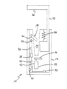
The brake disk lock 10 shown in the Figures comprises a lock body 12 that
forms
a mount 14 for a brake disk 16. To detect a brake disk 16 received in the
mount
14, the brake disk lock 10 has a brake disk detection device 18 that comprises
a
rotatably supported detection lever 20 that projects into the mount 14, that
is
rotated by a brake disk 16 received in the mount 14, and that actuates a
switch
22. The switch 22 is arranged and configured such that it adopts a closed
state
when there is no brake disk 16 in the mount 14 and adopts an open state when a
brake disk 16 is received in the mount 14.
To secure the brake disk 16 received in the mount 14, the lock 10 comprises a
latch 24 that is displaceably supported in the lock body 12 and that has a
latch
pin 26 in the region of its end remote from the lock body 12 that extends
transversely to the direction of displacement and that can be led through a
bore
17 provided in the brake disk 16.
CA 3042786 2019-05-09
6
The latch 24 can be displaced from an open position (Fig. 1) partly moved out
of
the lock body 12 in which a mounting of the lock at a brake disk 16 is
possible
against the return force of an opening spring 28 into a closed position in the
lock
body 12 in which the latch 24 is blocked or locked by means of a locking
element
30 (Fig. 2).
To open the lock 10, the locking element 30 can be released from the latch 24
with the aid of an unlocking motor 32, here in the form of an electric motor,
so
that the latch 24 is urged into its open position by the opening spring 28,
that is
so-to-say jumps open.
The latch 24 can be moved into the lock body 12 beyond its closed position
(Fig.
2) by pressing the latch 24 and the lock body 12 together until said latch 24
reaches an overlift position (Fig. 3) that is detected by an overlift switch
34.
The lock further has a sensor 36 for detecting a positional change of the lock
10.
The sensor 36 can, for example, be an acceleration sensor.
The sensor 36 is connected to an alarm module that outputs an alarm, in
particular an acoustic alarm, when the brake disk detection device 18 detects
a
brake disk 16 received in the mount 14 and the sensor 36 detects a relevant
positional change. A relevant positional change can be present, for example,
when the position of the lock 10 relative to a starting position of the lock
10
changes by more than a predefined amount in at least one spatial direction. A
relevant positional change can in particular be present when the sensor 36
detects an angular change at the lock 10 about at least one spatial axis that
that
is larger than 4 , for example.
That position of the lock 10 is called the starting position of the lock 10
that the
sensor 36 determines when the brake disk detection device 18 detects the
presence of a brake disk 16 in the mount 14 and the lock 10 has not changed
its
CA 3042786 2019-05-09
7
position for a predefined minimum period in the range of some seconds, for
example of 5 seconds.
To check the authorization of a user operating the lock 10, the lock 10
furthermore has an authentication module 40 that has a Bluetooth enabled
transmission/reception unit 42 that is configured to establish a wireless
connection to a mobile end device, not shown here, of the user, for example to
a
smartphone, to a smart watch, or to a remote control associated with the lock
10
to authenticate the user by means of the mobile end device.
The authentication module 40 is connected to the overlift switch 34 and is
activated as soon as the overlift switch 34 is actuated. To activate the
authentication module 40 and to trigger an authentication process, the user
therefore deliberately has to press the latch 24 and the lock body 12 together
beyond the closed position of the latch 24 until the latch 24 reaches its
overlift
position and the overlift switch 34 is actuated. The overlift switch 34 in
other
words therefore forms an actuation element 34 whose actuation is a requirement
for an unlocking of the lock 10.
If not only the unlocking should take place electronically, but also the
locking of
the lock 10, it is conceivable that the latch 24 also has to be moved into its
overlift position for the locking to actuate the overlift switch 34 and hereby
to
activate the authentication module 40 and to trigger an authentication
procedure.
Since the actuation of the actuation element 34 will typically not take place
without a positional change of the lock 10 detected by the sensor 36, the
alarm
module 38 necessarily outputs an alarm on an actuation of the actuation
element
34. The authentication module 40 can, however, determine on the basis of the
user authentication triggered by the actuation of the actuation element 34
whether the movement of the lock 10 has taken place by an authorized user, in
which case the alarm is switched off.
CA 3042786 2019-05-09
8
If the user authentication does not take place successfully, but if
simultaneously
no further positional change of the lock 10 is detected, it is assumed that
the
positional change of the lock 10 triggering the alarm was unintentional and
the
.. alarm is likewise switched off.
It is only assumed that an unauthorized attack on the lock 10 has taken place
in
the event of an unsuccessful user authentication and a continued movement or
positional change of the lock and the alarm output is maintained as protection
.. against theft.
Finally, the lock 10 also comprises a visual and/or acoustic status display 44
for
signaling the charge state of an energy supply, not shown, of the lock 10 that
is
activated on every activation of the unlocking motor 32.
CA 3042786 2019-05-09
9
Reference numeral list
lock
12 lock body
5 14 mount
16 brake disk
17 bore
18 brake disk detection device
detection lever
10 22 switch
24 latch
26 latch pin
28 opening spring
locking element
15 32 unlocking motor
34 overlift switch
36 sensor
38 alarm module
authentication module
20 42 transmission/reception unit
44 status display
CA 3042786 2019-05-09