Note: Descriptions are shown in the official language in which they were submitted.
CA 03042881 2019-05-03
WO 2018/083453 PCT/GB2017/053256
1
IMPROVEMENTS IN OR RELATING TO THE MONITORING OF FLUID
FLOW
Technical Field of the Invention
The present invention relates to monitoring fluid flow. In particular, the
present
invention relates to monitoring of fluid flow at, but not limited to, low
Reynolds
numbers using differential pressure flow meters.
Background to the Invention
The flow measurement of fluids is vitally important to the world economy. Not
only through having accurate values for the quantities of goods bought or
sold, but for
the safe and continued operation of processes across all industries. Without
accurate
measurement control, optimisation, trade and most importantly safe operation
could not
be achieved. Accurate flow measurement is achieved through the use of
repeatable flow
meters which are applied following industry best practice.
A particularly well known type of flow meter technology is called a
differential
pressure flow meter which is based around the use of primary element within a
pipe.
The primary element can have many different geometries but typically consists
of an
obstruction or an expansion in the pipe that causes a variation in the static
pressure of
the system. By measuring the differential pressure between immediately
upstream of
the primary element and at a point where the pressure has changed due to the
primary
element, the volumetric or mass flow rate can be determined. The mechanism
that
relates the differential pressure to the volumetric or mass flow rate can be
derived from
Bernoulli's theorem which is based on the conservation of energy within a
flowing
fluid. Bernoulli's theorem uses the assumption of an inviscid flow. However,
in practice
CA 03042881 2019-05-03
WO 2018/083453 PCT/GB2017/053256
2
this assumption is invalid and a correction factor called a discharge
coefficient is used
to correct practical measurements to theory.
As stated, there are many types of primary element with the most common being
orifice plates, Venturis, cone and wedges. Nevertheless, any installation that
causes a
repeatable, reproducible and measurable pressure differential can be
considered a
primary element e.g. Coriolis meter, turbine meter, reduced bore ultrasonic
meter,
valves, process equipment, etc. Whichever primary element is used in a
differential
pressure meter, the fundamental operation and equations are the same and
differ only
in the geometries and respective geometric parameter calculation i.e. beta.
For all
differential pressure flow meter types, the density of the fluid being
measured is also
required to complete the calculation of mass or volumetric flow rate.
Differential pressure flow meters are widely used in industry as they provide
accurate measurements, linear discharge coefficients, are robust and have
prescriptive
standards, are easy to maintain and have a theory of operation that is
straightforward to
understand. These advantages have been instrumental to differential pressure
flow
meters attaining a large and continued market share of world flow meter sales.
However, these advantages only apply in high Reynolds number applications with
some
standards stating a lower limit of applicability of 200,000 Reynolds number
(ISO
5167:2003-4 Venturis). Fluid flows above a Reynolds number of 200,000 are
typical of
gases, water and other liquids with a low viscosity.
At lower Reynolds numbers, the linearity of the discharge coefficient
deteriorates significantly, the accuracy is critically dependent on knowing
the operating
Reynolds number and most written standards do not apply. This effect is
compounded
CA 03042881 2019-05-03
WO 2018/083453 PCT/GB2017/053256
3
the lower the Reynolds number is with even very small changes in Reynolds
number
causing large mis-measurement issues. In addition to the above, the fluid flow
mechanism changes at very low Reynolds numbers (below 10,000 depending on
fluid)
and the flow regime can turn from turbulent flow, to transitional through to
laminar
flow. Each flow mechanism has its own effect on the measurement performance of
differential pressure flow meters. It should be stated that all flow meters
will have a
Reynolds number affect to varying degrees. Fluid flows below a Reynolds number
of
20,000 are typical of higher viscosity fluids.
Differential pressure flow meters have been shown to be repeatable and
reproducible in turbulent, transition and laminar flows. The issue lies in the
fact that the
operating Reynolds number is unknown in practice and without this it is
impossible to
correct the flow meters performance. Determining the operating Reynolds number
requires additional measurements of physical properties adding to cost and
complexity.
Even so, it may still be difficult to determine the Reynolds number with
sufficient
accuracy to make reliable calculations of the flow rate.
It is therefore an object of the present invention to address problems with
the prior art.
Summary of the Invention
According to a first aspect of the present invention there is provided a
method
of monitoring fluid flow, the method comprising the steps of: measuring a
pressure
differential across a differential pressure flow meter A/31; measuring the
line pressure
APf
drop due to friction A/3f. along a length of pipe L ; and calculating the
quantity ¨, and
thereby calculating one or more properties of the flow.
CA 03042881 2019-05-03
WO 2018/083453 PCT/GB2017/053256
4
The present method thus facilitates the calculation of various properties of
the
APf flow from the quantity ¨ independent of the specific physical properties
of the fluid.
Calculating flow properties in line can enable the use of differential
pressure flow
meters for low Reynolds number flows.
The method is preferably applied in laminar flow conditions or in the low
Reynolds number region of turbulent flow. In this context the low Reynolds
number
region of turbulent flow is below Reynolds number values where the flow is not
considered fully turbulent. Nevertheless, some aspects of the method will work
in larger
Reynolds number regions.
The method may be used with any suitable form of differential pressure flow
meter. Suitable forms of differential pressure flow meter include but are not
limited to:
orifice plates, Venturi meters, Dall tubes, Pitot tubes, multi-hole pressure
probes, cone
meters, wedge meters, Coriolis meters, turbine meters, reduced bore ultrasonic
meter,
valves, process equipment and the like. In further embodiments, the
differential flow
meter may comprise any other form of obstruction or expansion or overall
pressure loss
that provides a repeatable, reproducible and measurable pressure differential.
The line pressure drop LPf may be measured along any length of like
dimensioned pipe in direct series with the differential pressure flow meter.
In one
embodiment, the line pressure drop LPf is measured along a length of pipe
directly
upstream of the differential pressure flow meter.
CA 03042881 2019-05-03
WO 2018/083453 PCT/GB2017/053256
The method may be used to calculate the Darcy-Weisbach friction factor,A,
AP
from the product of the quantity t and a constant related to meter geometry
Cm. In
such embodiments, the constant Cm may be calculated from
D(1 ¨ IV)
Cm = ________________________________________
Cd 2 L 16'4
5 Where D is the pipe diameter, /3 is a constant related to the structure
of the meter
and Cd is the discharge coefficient. In the case of orifice plates and Venturi
meters, 16'
is the ratio of the internal throat diameter d to the pipe diameter D. In the
case of other
forms of differential pressure flow meters, 16' has other well known
definitions. In the
case where other suitable obstructions or expansions are used as differential
flow
meters, an effective /3 can be calculated.
The method may include the steps of calculating the discharge coefficient of
the
flow. The calculation of the discharge coefficient of the flow meter may be
achieved
by knowledge of the relationship between discharge coefficient and friction
factor or
by knowledge of the relationship between discharge coefficient and Reynolds
number.
The discharge coefficient of the flow may be calculated from the calculated
Darcy-
Weisbach friction factor A as:
Cd = f (A)
The discharge coefficient of the flow may be calculated from the calculated
Reynolds number Re as:
Cd = f (Re)
CA 03042881 2019-05-03
WO 2018/083453 PCT/GB2017/053256
6
Knowledge of the relationship between discharge coefficient and friction
factor,
and discharge coefficient and Reynolds number, can be obtained from a
calibration of
the measurement system or by other means.
The method may include the steps of calculating the discharge coefficient and
friction factor by means of iteration using the relationship between discharge
coefficient
AP
and friction factor and the relationship between friction factor and the
quantity
In some embodiments, the method may include the step of determining an
operational corrected value, Aõr, of the calculated Darcy-Wei sbach friction
factor A..
This enables compensation for variations in pipe conditions. The corrected
value
Aõr may be related to the calculated value A. by:
Athe
Acor = A
Where A.catib is the friction factor value measured during calibration of the
differential pressure flow meter and Athe is the theoretical value of the
Darcy-Weisbach
friction factor. In ideal conditions A, should equal Athe .
The method may include the further step of calculation of the flow rate. The
calculation may be achieved using the equation:
7rd2
4 l2 (LP)
Q¨ CdE
-µ I (1 ¨ fl4) P
Where Q is the volumetric flowrate, E is the expansibility of the fluid (equal
to
1 for incompressible fluids) and p is the density. In such embodiments, the
density may
CA 03042881 2019-05-03
WO 2018/083453 PCT/GB2017/053256
7
be determined by standard methods including but not limited to sampling of the
fluid
and off-line laboratory analysis.
The method may include the additional step of calculating the Reynolds number
of the flow. The Reynolds number of the flow may be calculated from the
calculated
Darcy-Weisbach friction factor A or from the operational corrected value,
2.õ,, of the
calculated Darcy-Weisbach friction factor. The calculation of the Reynolds
number of
the flow may be achieved by using well known correlations of friction factor
and
Reynolds number such as
64
A = ¨
Re
in laminar flow or the Colebrook-White equation (or similar correlations) for
turbulent flows.
In some embodiments, the method may include the step of calculating an
operational corrected value, Reõr, of the calculated Reynolds number Re. This
enables
compensation for variations in pipe conditions. The corrected value Reõr may
be
related to the calculated value Re by:
Reref
Recor = D Re
ecalib
Where Recaub is the Reynolds number value measured during calibration of the
differential pressure flow meter and Reref is the reference value of the
Reynolds
number.
In some embodiments, the method may include the steps of calculating the
discharge coefficient from the Reynolds number, where the Reynolds number is
CA 03042881 2019-05-03
WO 2018/083453 PCT/GB2017/053256
8
determined from the calculated Darcy-Weisbach friction factor A. This may be
achieved by means of iteration using the relationship between the discharge
coefficient
and the Reynolds number, the relationship between the Reynolds number and the
Darcy-Weisbach friction factor A and the relationship between Darcy-Weisbach
friction
AP
.. factor A and the quantity
The method may include the steps of calculating the density, p, of the flow.
The
density p may be calculated from the calculated Darcy-Weisbach friction factor
A or
from the operational corrected value, Aõ, , of the calculated Darcy-Weisbach
friction
factor. The calculation of the density p may be achieved using knowledge of
the
velocity, u, in the pipe where the measurement of LPf is taken. In such cases,
the
method may involve the additional step of determining the velocity of the
fluid in the
pipe. The velocity may be measured within the length L along which the line
pressure
drop due to friction LPf is measured. The velocity may be measured at a
location
outside the length L with the velocity within L being determined therefrom.
Preferably,
the velocity measurement is taken at a sufficient separation from the
differential
pressure flow meter such that the variation in velocity due to the flow
restriction of the
primary element does not impact on measurement. In some embodiments, the
velocity
measurement may be acquired from the primary element. This may be the case
where
an intrusive flow meter is used. Examples of intrusive flow meters include but
are not
limited to Coriolis meters or turbine meters.
In such embodiments, the density may be calculated from the measured
velocity. In particular, the density may be calculated from the calculated
Darcy-
CA 03042881 2019-05-03
WO 2018/083453
PCT/GB2017/053256
9
Weisbach friction factor A or from the operational corrected value, Aõr, of
the
calculated Darcy-Weisbach friction factor and the measured velocity.
In such embodiments, the density, p, of the flow may be calculated using:
2AP D
P = __________________________________ ALu2
In such embodiments, preferably the density, p, of the flow is calculated
using:
2AP D
P = _______________________________________
¨cor--2
The method may involve an iteration of the density equation above and the
differential pressure meter flow equation to calculate the density in place of
velocity
measurement. Given a target value (e.g. from a calibration), it is possible to
attain
optimal values for both the density and corrected flow based on these equation
and the
measurements of A/31, LPf and gained knowledge of Darcy-Weisbach friction
factor A
and discharge coefficient C.
In some embodiments, the method may include the step of determining an
operational corrected value, p,, of the calculated flow density p. The
corrected value
PCOT may be related to the calculated value p by:
Pre f
Pcor =
Pcalib
Where n
calib is the density value measured during calibration of the differential
pressure flow meter and pref is the reference value of the density of the
fluid during
calibration conditions.
CA 03042881 2019-05-03
WO 2018/083453 PCT/GB2017/053256
The method may include the steps of calculating the viscosity, u, of the
fluid.
The viscosity pt. may be calculated from the calculated density p or from the
operational
corrected value,
col', of the calculated density.
In such embodiments, the viscosity, u, of the flow may be calculated using:
pDu
5 = __ Re
In such embodiments, preferably the viscosity, u, of the flow is calculated
using:
PcorDu
= Re
In some embodiments, the method may be used to calibrate a differential
pressure flow meter. In such embodiments, the method may incorporate the
additional
10 .. step of installing the differential pressure flow meter in a test pipe.
Subsequently, the
method may include measuring across the full Reynolds number range required
APi
and LPf . In such embodiments, the method may involve the further step of
calculating
AP
across the full Reynolds number range required the quantity t and thereby
calculating
calibration coefficients for the use of the differential pressure flow meter.
The
calibration coefficients calculated may vary with variation in the Reynolds
number of
the flow. The calibration coefficients calculated may include any one or more
of: the
Darcy-Weisbach friction factor ,Athe , the discharge coefficient or density
Pre f
P calib
According to a second aspect of the present invention there is provided a
method
of calibration of an differential pressure flow meter for monitoring fluid
flow
comprising the steps of: installing the differential pressure flow meter in a
test pipe;
measuring across the full Reynolds number range required: a pressure
differential
CA 03042881 2019-05-03
WO 2018/083453 PCT/GB2017/053256
11
across the differential pressure flow meter A/31; and the line pressure drop
due to friction
A/3f. along a length L of pipe; calculating across the full Reynolds number
range required
AP
the quantity ¨I. ; and thereby calculating calibration coefficients for the
use of the
differential pressure flow meter.
The method of the second aspect of the present invention may incorporate any
or all features of the first aspect of the present invention as required or as
desired.
The method of calibration may include the further steps of: installing the
differential pressure flow meter in an operation setting; measuring in
operation a
pressure differential across a differential pressure flow meter A/31; and the
line pressure
AP
drop due to friction A/3f. along a length L of pipe; calculating the quantity
¨I. ; and
thereby calculating live values of correction parameters.
According to a third aspect of the present invention there is provided an
apparatus for monitoring fluid flow, the apparatus comprising: a differential
pressure
flow meter; pressure sensing elements operable to measure a pressure
differential across
a differential pressure flow meter A/31; pressure sensing elements operable to
measure
the line pressure drop due to friction A/3f. along a length L of pipe; and a
flow property
AP
processing unit operable to calculate the quantity t and to thereby calculate
one or
more flow properties.
The apparatus of the third aspect of the present invention may incorporate any
or all features of the first or second aspects of the present invention as
required or as
desired.
CA 03042881 2019-05-03
WO 2018/083453 PCT/GB2017/053256
12
The pressure sensing elements may comprise of differential pressure
transmitters, static pressure transmitters, manometers or any device fit for
purpose to
measure or calculate differential pressure to sufficient accuracy.
The differential pressure flow meter may comprise any of: orifice plates,
Venturi meters, Da11 tubes, Pitot tubes, multi-hole pressure probes, cone
meters, wedge
meters, Coriolis meters, turbine meters, reduced bore ultrasonic meter,
valves, process
equipment and the like. In further embodiments, the differential flow meter
may
comprise any other form of obstruction or expansion or overall pressure loss
that
provides a repeatable, reproducible and measurable pressure differential.
The line pressure drop LPf may be measured along any length of like
dimensioned pipe in direct series with the differential pressure flow meter.
In one
embodiment, the line pressure drop LPf is measured along a length of pipe
directly
upstream of the differential pressure flow meter.
The apparatus may additionally comprise one or more velocity sensing elements
operable to determine the velocity, u, of fluid in the flow. The velocity
sensing
elements may be positioned so as to measure the velocity within the within the
length
L along which the line pressure drop due to friction LPf is measured. The
velocity may
be measured at a point outside the length L with the velocity within L being
determined
therefrom. Preferably, the velocity sensing elements are positioned such that
the
velocity measurement is taken at a sufficient separation from the orifice
plate, such that
the variation in velocity due to the differential pressure flow meter does not
impact on
measurement.
CA 03042881 2019-05-03
WO 2018/083453 PCT/GB2017/053256
13
The velocity sensing elements may comprise ultrasonic velocity sensing
elements (either clamp-on or inline), insertion probe type devices, or any
other velocity
sensing device fit for purpose. If located upstream of the differential
pressure flow
meter consideration must be given to not impacting the flow profile entering
the
.. differential pressure flow meter. The velocity sensing element itself may
be the primary
element. This may be the case where an intrusive flow meter is used. Examples
of
intrusive flow meters include but are not limited to Coriolis meters or
turbine meters.
The flow property processing unit may be operable to calculate any one or more
of: the Darcy-Weisbach friction factor A, the discharge coefficient, the
density p, the
Reynolds number Re, the viscosity pt. or the corrected volumetric flow rate Q.
Such
parameters and others may be calculated according to the methods outlined in
the first
aspect of the present invention.
In embodiments wherein the differential pressure flow meter has been
calibrated
before use and calibration factors have been calculated, the flow property
processing
unit may be operable to calculate an operational corrected value of all
calculated values
by the methods outlined in the first aspect of the present invention.
The apparatus may be provided with an interface. The interface may be
operable to enable the output of calculated flow values. The interface may be
operable
to enable the output of other status information relating to the flow or the
operation of
the apparatus. The interface may be operable to enable the input of control
signals.
The interface may be operable to enable the input of calibration coefficients
or other
coefficients relating to the fluid or the flow.
CA 03042881 2019-05-03
WO 2018/083453 PCT/GB2017/053256
14
In embodiments wherein the reference density of the fluid, põ f , is known,
the
flow property processing unit may be operable to calculate an operational
corrected
value,
col', of the calculated flow density p by the methods outlined in the first
aspect
of the present invention.
According to a fourth aspect of the present invention, there is provided a
calibration apparatus for calibrating a differential pressure flow meter, the
calibration
apparatus comprising: a test pipe; a fluid supply for controllably introducing
fluid into
the test pipe so as to provide a flow with a desired Reynolds number; pressure
sensing
elements operable to measure the pressure differential across the differential
pressure
flow meter API; pressure sensing elements operable to measure the line
pressure drop
due to friction LPf along a length L of pipe; and a calibration coefficient
processing
AP
unit operable to calculate the quantity t and to thereby calculate one or more
calibration coefficients for the use of the differential pressure flow meter
across the full
Reynolds number range required.
The apparatus of the fourth aspect of the present invention may incorporate
any
or all features of the first, second or third aspects of the present invention
as required
or as desired.
The calibration coefficient processing unit operable to calculate any one of
any one or
more of: the Darcy-Weisbach friction factor ,Athe , Reynolds number, the
discharge
calib
coefficient or density Pre faccording to the method of the first aspect of the
present
P calib
invention.
CA 03042881 2019-05-03
WO 2018/083453 PCT/GB2017/053256
Detailed Description of the Invention
In order that the invention may be more clearly understood embodiments thereof
will now be described, by way of example only, with reference to the
accompanying
drawings, of which:
5 Figure 1 illustrates fluid flow through a circular cross-
section within a pipe;
Figure 2 illustrates fluid flow through an annular element with
circular cross-
section within a pipe;
Figure 3 illustrates flow through a pipe of circular cross-section;
Figure 4 is a graph illustrating the relationship between Darcy-
Weisbach friction
10 factor and Reynolds number;
Figure 5 illustrates fluid flow through a primary element in a circular
cross-
section pipe;
Figure 6 illustrates schematically an embodiment of an apparatus for
monitoring
flow according to the present invention;
15 Figure 7 is a flow chart illustrating an implementation of a
method of flow
monitoring with external density knowledge according to the present
invention;
Figure 8 is a flow chart illustrating another implementation of a
method of flow
monitoring involving calculation of all parameters according to the
present invention; and
Figure 9 illustrates schematically another embodiment of an apparatus
for
monitoring flow according to the present invention.
CA 03042881 2019-05-03
WO 2018/083453 PCT/GB2017/053256
16
The present invention provides for the measurement of a pressure differential
across a differential pressure flow meter APi and the line pressure drop due
to friction
AP
LPf along a length L of pipe. Subsequently, the quantity t is calculated,
enabling the
inline calculation of multiple properties of the flow.
Consider a fluid flowing through a circular cross section with radius, R, as
shown in Figure 1. Now consider a cylindrical element of the fluid with
length, L, and
radius, r, sufficiently far from the pipe wall to be outside the boundary
layer. The
driving force for this fluid is the differential pressure at either end of the
element which
must be greater than the pressure drop due to frictional forces acting on the
external
surface of the element.
For uniform flow, a force balance can be completed over the element as shown
in equation 1.
(P1 ¨ /32)n-r2 = -c2n-rdL (1)
where P1 and P2 are the static pressures at points 1 and 2 respectively, r is
the
radius of the fluid element, T is the viscous shear stress and L is the
distance between
points 1 and 2. Equation 2 places P2 in terms of P1.
P1n-r2 ¨ (P1 + ¨88PL dL) nr2 = -c2n-rdL (2)
The viscous shear stress can be defined as shown in equation 3.
dux
T = (3)
Where pt. is the viscosity of the fluid and u, is the point velocity of the
fluid
which varies with r. Applying the no slip condition at the pipe wall i.e. u, =
0 when
CA 03042881 2019-05-03
WO 2018/083453
PCT/GB2017/053256
17
r = R, substituting equation 3 into equation 2, letting ¨88PL = ¨ALP and
rearranging, then the
following integration can be completed (equations 4-6):
foux du = --1¨AP fRr r dr (4)
L
[ux]ox = ¨L' r2
(5)
L 1_2 IR
P 2 \ (6)
U = ¨ r
x A D2
Equation 6 is the equation for the velocity of the fluid at a certain radius,
r, from
the centre line.
Now consider an annular element of fluid within the pipe between radius r and
dr for which the velocity, ux, can be considered constant, as shown in Figure
2.
The volumetric flow rate of this annular element can be written as
dQ = ux2n-rdr (7)
The total rate of flow can therefore be found by integrating across the entire
pipe radius, R. However, an equation for uxhas already been found that is
dependent
on R. Substituting in equation 6 gives.
foQ dQ = ¨AP fir? r(R2 ¨ r2) dr (8)
L 0
Q AP [R2r2 r4 R
[Q] = ¨41 L 2 (9)
AP ,4
Q = ¨8 IC (10)
Equation 10 is called the Hagen-Poiseuille equation, developed independent by
both Hagen and Poiseuille in 1839 and 1840. This equation is valid only in
laminar
CA 03042881 2019-05-03
WO 2018/083453 PCT/GB2017/053256
18
flow. It is important as it allows us to derive the linear relationship of
Darcy-Weisbach
friction factor and Reynolds number for laminar flow applications.
Now consider a circular cross section of pipe with a pressure drop at the pipe
wall caused by a wall shear stress, Tw . Figure 3 shows this for a block of
fluid with
length, L, and pipe diameter, D.
Again, a force balance can be conducted over the fluid block between points 1
and 2.
irD2 irD2 irD2
P1 -4 - P2 = APf -4 = twffLD (11)
(12)
APf = 4-cw ¨D
The wall shear stress, Tw, is related to the kinetic energy per volume and can
be
written as in equation 13.
-cw =2 (13)
8
where A is the Darcy-Weisbach friction factor, p the density in kg/m3 and u is
the pipe velocity. Therefore, the pressure drop due to friction in the pipe
can be
expressed as in equation 14 and is valid for all Reynolds numbers.
Apu2L
APf ¨ (14)
¨ 2D
By combining equation 14 and equation 10 rearranged for velocity in terms of
pressure drop, an equation for friction factor in laminar flow only can be
derived.
Apu2L 32 Lu
(15)
2D D2
A = 64
(16)
puD
CA 03042881 2019-05-03
WO 2018/083453 PCT/GB2017/053256
19
64
Or A = ¨ (17)
Re
Equation 17 shows that in laminar flow, the friction factor is inversely
proportional to Reynolds number only. This suggests that measuring friction
factor in
the laminar flow region will allow a direct calculation of Reynolds number. It
follows
that if the discharge coefficient is repeatable in laminar flow it can
accurately be
correlated with Reynolds number or indeed friction factor itself to provide
inline
corrections.
It is not only laminar flow where friction factor is dependent on Reynolds
number. There are several well known correlations for friction factor in
turbulent flows
e.g. Colebrook¨White equation that would perform a similar role to equation
17. In
these cases the dependence on Reynolds number is not linear but the same
process can
be used to calculate discharge coefficient. Figure 4 shows the well known
Moody plot
of Darcy-Weisbach friction factor versus Reynolds number for a number of
different
relative roughness' of pipe.
Note the differences in friction factor for both laminar and turbulent flows.
Also
note the line of fully turbulent flow with everything on the right hand side
of this line
showing friction factor being independent of Reynolds number.
Friction factor is an important contributor to the invention but an
understanding
of differential pressure flow measurement is also required. Consider a
circular cross
section of pipe with a primary element which concentrically reduces the cross
sectional
area available for flow, as shown in Figure 5.
CA 03042881 2019-05-03
WO 2018/083453 PCT/GB2017/053256
Assuming inviscid and incompressible flow of the fluid and no change in
elevation, from the Bernoulli equation and conservation of energy in the
system, the
energies at point 1 and point 2 can be written as in equation 18:
2 1 2
P1 + -,0U1 = P2 + -2 PU2 (18)
5 Where u1
and u2 are the velocities at point 1 and 2 respectively. From a mass
balance through the system and assuming a constant fluid density, the
flowrates at each
point will be equal. Therefore equation 18 can be written as
\ 2 2
P1 + -1P ( 1) = P2 P (¨Qyrd2 (19)
2 IrD2 2
4 4
Where d is the throat diameter at point 2. Rearranging equation 19 in terms of
10 Q gives equation 20.
d2 1 \12 (Pi- P2)
Q = P (20)
4 (1-G5d)4)
The ratio of the pipe diameter to the throat diameter ¨Dd is often called beta
P. The
inclusion a parameter known as the Discharge Coefficient Cd helps remove
errors
associated with assumptions and location of pressure measurements. Finally, a
term to
15 correct
for the expansibility of the fluid E is included with E equal to 1 for
incompressible fluids.
The final equation for the calculation of volume flow through a primary
element
(similar to a Venturi or orifice plate) is therefore
Q =
i -P2) (21)
CdEird2 _____________________________
CA 03042881 2019-05-03
WO 2018/083453
PCT/GB2017/053256
21
Or
Q = Cd ____________________________ Tr4c12 12(APi)
_\ (22)
The invention is derived from creating a measurement system that combines the
differential pressure flow rate equation (equation 22) with the Darcy-Weisbach
friction
factor equation (equation 14). Combining these two principles creates a
powerful tool
providing more information than either singularly.
Turning now to Figure 6, a differential pressure meter is provided within a
metering run and is operable to measure a pressure drop, A/31, across the
differential
pressure meter. Additionally, the pressure drop, A/3f, due to friction across
a straight
length of pipe is measured. In Figure 5, an orifice plate is shown but in
practice, the
differential pressure primary element can be any obstruction or expansion that
generates
a repeatable, reproducible and measurable pressure differential. Utilising
these two
measurements can facilitate the calculation of various fluid properties as is
explained
further below.
Apu2L
APf = (14)
2D
In equation 14 (reproduced above), a velocity measurement, amongst others, is
required in order to calculate the friction factor. The velocity can be
calculated from the
volumetric flow through the differential pressure flow meter by equation 23.
U = (23)
4
CA 03042881 2019-05-03
WO 2018/083453 PCT/GB2017/053256
22
where Q is the volumetric flow rate. Replacing the volumetric flow rate term
in
equation 23 with the theoretical equation for flow measurement using a
differential
pressure device (equation 22) yields equation 24 (removing = 1).
ird2
Q = CdE V(1-4)34)2( AP1)
(22)
u2 = 2C2 )64 d API
(24)
p(1-)64)
Where d is the internal diameter of the throat of the orifice, 16' is the
ratio of the
throat diameter to pipe diameter and APi is the pressure drop due to the
throat
restriction.
Now, substituting Equation 24 back into Equation 14 removes the density term
leaving an equation for friction factor that is independent of the physical
properties of
the fluid being measured. Equation 25 shows two terms; one a ratio of two
differential
pressure measurements and two a constant relating to meter geometry, pipe
length and
discharge coefficient.
,., AP f
A = r, (25)
pa-p4)
Where, cm = (26)
cp,p4
By measuring the pressure drop APi across the differential pressure meter and
the pressure drop LPf along a length of pipe, and with knowledge of the pipe
and meter
geometry, it is possible to calculate friction factor in line using equations
25 and 26.
This can translate to a more accurate Reynolds number from equation 17 for
laminar
flow and any well known correlation such as Colebrook-White for turbulent
flow.
CA 03042881 2019-05-03
WO 2018/083453 PCT/GB2017/053256
23
Equation 25 should deliver a repeatable correlation for friction factor. This
correlation is independent of physical properties of the fluid.
Applying the described calculation method in practice can be accomplished by
two real-time differential pressure measurements only. These measurements will
be
made subject to standard practices in terms of ensuring a sufficiently low
uncertainty
in their measurements and regular calibrations and maintenance as described in
many
operating procedures and good practice documents.
Knowledge is also required of the geometry of pipe work and primary element
as well as an indication of the systems performance i.e. discharge coefficient
over the
useable Reynolds number range and hence friction factor range. This can be
accomplished by a calibration and characterisation of the measurement system
or by
some other method. Each method will have a different level of accuracy and
uncertainty. Accordingly, the skilled man will aim to select a calibration and
characterisation method that will deliver optimal results in the particular
circumstances.
Typically, characterisation and calibration will allow the establishment of an
equation
or similar to relate discharge coefficient as a function of friction factor
(equation 27) or
to relate discharge coefficient as a function of Reynolds number (equation
28).
Cd = f(2L) (27)
Cd f (Re) (28)
Using the established relation and equation 25 it is possible to determine the
friction factor, Reynolds number and discharge coefficient for the measurement
system.
This can be achieved using an iterative approach. Alternatively, it may be
beneficial to
compare this calculated friction factor or Reynolds number value with the
theoretical
CA 03042881 2019-05-03
WO 2018/083453 PCT/GB2017/053256
24
or reference value. A simple ratio of the calculated to reference values
allows for the
calculation of a corrected friction factor and corrected Reynolds number as
shown in
equations 29 and 30 respectively.
¨cor¨the This in turn aligns the measured values with
theory.
Athe
ACOT = Acalc (29caith
Re ref
Rec., = Reca ,c (30)
Re ca/lb
Where Acaub is the calculated friction factor value during calibration, Acalc
is
calculated friction factor during operation, A, is the theoretical friction
factor for the
reference Reynolds number, Re,,b is the calculated Reynolds number during
calibration, Rec., is the calculated Reynolds number during calibration and
Reref
is the reference Reynolds number during calibration.
Using the friction factor method, the correct discharge coefficient can be
calculated independently of the physical properties of the fluid. Equation 22
can now
be used to calculate the corrected volumetric flow rate of the fluid (Note:
Density of the
fluid would still be required to complete the calculation. This can be
obtained from
standard sources e.g. fluid sampling).
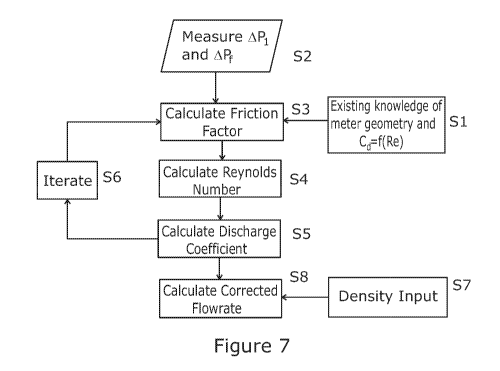
Turning now to figure 7, the process steps in determining flow properties in
accordance with an implementation of the method of the present invention are
set out
in a schematic flow chart. At the initial step, Si, a relation (equation 27 or
28) is
established (or looked up) between the discharge coefficient and the Reynolds
number.
Subsequently, at S2, the pressure differential, A/31, across the differential
pressure meter
CA 03042881 2019-05-03
WO 2018/083453 PCT/GB2017/053256
and the pressure drop APf along a length of pipe are measured. At S3, the
Darcy-
Weisbach friction factor can be calculated using equation 25. In some
implementations,
this can involve calculating a corrected value of the friction factor as set
out in equation
29. At S4, the friction factor is used to calculate a value for the Reynolds
number of
5 the
flow, for instance using equation 17 or Colebrook-White equation. In some
implementations, this can involve calculating a corrected value of the
Reynolds number
as set out in equation 30.
At S5, the discharge coefficient can be calculated using the calculated or
corrected value of the Reynolds number. In some embodiments, the value of the
10
discharge coefficient calculated at S5 may be iterated back to the calculation
of the
friction factor at S3 through the iteration process at S6.
At S7, the density of the fluid is established by sampling, looking up or
other
appropriate method. Subsequently at S8, the established density value is used
to
calculate a flowrate of the fluid using equation 21 or 22 as appropriate.
15 In
further implementations of the invention, it is possible to use knowledge of
the friction factor and discharge coefficient to infer the density of the
fluid in real-time.
From equation 14, the unknowns are density and velocity of the fluid.
Rearranging in
terms of density gives equation 31.
2APfD
p = ______________________________________
ALu2 (31)
20 The
velocity can be measured using a suitable measurement device such as a
clamp-on ultrasonic meter or the like. The measured velocity may then be used
to
calculate the density using equation 31.
CA 03042881 2019-05-03
WO 2018/083453 PCT/GB2017/053256
26
In another implementation, it is not necessary to measure the velocity.
Instead,
combining equation 14 and 22, there are two equations with two unknowns. It is
possible to iterate these two values to provide a density and a corrected
volumetric
flowrate. This may be applicable where indications of a target density are
known e.g.
in water applications where the physical properties are relatively well known.
As with friction factor, correction of the density can be made on initial
meter
calibration by using equation 32.
Pre f
Pcor = P calib Pcalc (32)
where Pcor is the corrected density, pref. is the reference density during
calibration, D caub is the calculated density during calibration and pcaic is
the calculated
density during operation.
When the density is known, it is further possible to calculate the viscosity
of the
fluid, it. Knowledge of the density, pipe diameter, velocity and Reynolds
number
(derived from friction factor) allows viscosity to be calculated using the
standard
Reynolds number, Re, calculation equation as shown in equation 33.
pDu
= (33)
Re
Turning now to figure 8, a flow chart illustrating the additional steps in
implementations involving the calculation of flow properties using the above
techniques is shown. For ease of understanding, steps in figure 8 are given
reference
numerals corresponding to like steps in figure 7.
In figure 8, S1-S6 and S8are identical to those in figure 7. S7 differs in
that the
density is calculated either from a velocity measurement using equation 31 or
from
CA 03042881 2019-05-03
WO 2018/083453 PCT/GB2017/053256
27
knowledge of a target density. In some embodiments, the value of the flowrate
calculated at S8 may be iterated back to the calculation of the density at S7.
At S10, the viscosity is calculated using equation 33. This calculation can
use
a measured velocity or the velocity equivalent of the flowrate calculated at
S8.
Typically, the calculation would also use the Reynolds number calculated at S4
and
density value at S7.
In order to implement the above methods, a flow monitoring apparatus
according to Figure 9 can be utilised with the pipe and orifice plate of
figure 6. As
shown in Figure 9, a pair of sensing elements 1, 2 are operable to detect the
differential
pressure APf along the upstream length of pipe and the pressure drop APiacross
the
orifice plate flow meter. In preferred implementations, the sensing elements
are direct
differential pressure sensors and transmitters but other methods to deliver or
infer the
differential pressure of these locations could be accommodated. For
implementations
where velocity is measured, a velocity sensing element 3 is provided. The
output of
each sensing element 1, 2, 3 is fed to a flow property processing unit 4
operable to
AP
calculate the quantity t and to thereby calculate one or more flow properties
as set
out above.
Before installing an orifice plate flow meter as part of an apparatus above or
implement the above methods on such an arrangement, the flow meter may be
calibrated. This can be achieved by installing the flow meter in a suitable
test pipe line
equipped with suitable sensing elements and a suitable supply of fluid for
simulating
flow with Reynolds numbers across the desired range of use. The differential
pressure
AP
ratio ¨I. can then be calculated across the desired range of Reynolds numbers.
CA 03042881 2019-05-03
WO 2018/083453 PCT/GB2017/053256
28
Subsequently, this can be used to calculate all the above mentioned flow
parameters
including the calibration parameters Acaub, Reõ,,b and 0
calib=
Subsequently, it is possible to determine suitable corrections such as Acor
and
PCOT as described above to compensate for variations in the pipe set up used
in
operation.
In summary, from knowledge of meter and pipe geometry and previous
knowledge of discharge coefficient as a function of friction factor or
Reynolds number,
it is possible to calculate a wealth of information about flowing fluid from
two
differential pressure measurements and an indicative pipe velocity only. The
information that can be provided includes:
= Friction factor
= Reynolds number
= Discharge coefficient
= Density
= Viscosity
= Corrected flowrate
The above embodiments are described by way of example only. Many variations
are possible without departing from the scope of the invention as defined in
the
appended claims.