Note: Descriptions are shown in the official language in which they were submitted.
.% 85206479
=
LOW FIELD MAGNETIC RESONANCE IMAGING METHODS AND APPARATUS
This application is a divisional of Canadian Patent Applicaton Number
2,960,189 filed
September 4, 2015.
BACKGROUND
[0001] Magnetic resonance imaging (MRI) provides an important
imaging modality
for numerous applications and is widely utilized in clinical and research
settings to produce
images of the inside of the human body. As a generality, MRI is based on
detecting magnetic
resonance (MR) signals. which are electromagnetic waves emitted by atoms in
response to
state changes resulting from applied electromagnetic fields. For example,
nuclear magnetic
resonance (NMR) techniques involve detecting MR signals emitted from the
nuclei of excited
atoms upon the re-alignment or relaxation of the nuclear spin of atoms in an
object being
imaged (e.g., atoms in the tissue of the human body). Detected MR signals may
be processed
to produce images, which in the context of medical applications, allows for
the investigation
of internal structures and/or biological processes within the body for
diagnostic, therapeutic
and/or research purposes.
[0002] MRI provides an attractive imaging modality for
biological imaging due to the
ability to produce non-invasive images having relatively high resolution and
contrast without
the safety concerns of other modalities (e.g., without needing to expose the
subject to
ionizing radiation, e.g., x-rays, or introducing radioactive material to the
body). Additionally.
MRI is particularly well suited to provide soft tissue contrast, which can be
exploited to
image subject matter that other imaging modalities are incapable of
satisfactorily imaging.
Moreover, MR techniques are capable of capturing information about structures
and/or
biological processes that other modalities are incapable of acquiring.
However, there are a
number of drawbacks to conventional MRI techniques that, for a given imaging
application,
may include the relatively high cost of the equipment, limited availability
(e.g., difficulty and
expense in gaining access to clinical MRI scanners), the length of the image
acquisition
process, etc.
[0003] The trend in clinical MRI has been to increase the field
strength of MRI
scanners to improve one or more of scan time, image resolution, and image
contrast, which in
turn drives up costs of MRI imaging. The vast majority of installed MRI
scanners operate
using at least at 1.5 or 3 tesla (T), which refers to the field strength of
the main magnetic field
BO of the scanner. A rough cost estimate for a clinical MRI scanner is on the
order of one
million dollars per tesla, which does not even factor in the substantial
operation, service, and
maintenance costs involved in operating such MRI scanners.
1
CA 3043063 2019-05-13
WO 2016/037025 PCT/US2015/048470
[0004] Additionally, conventional high-field MRI systems typically
require large
superconducting magnets and associated electronics to generate a strong
uniform static
magnetic field (BO) in which a subject (e.g., a patient) is imaged.
Superconducting magnets
further require cryogenic equipment to keep the conductors in a
superconducting state. The
size of such systems is considerable with a typical MRI installment including
multiple rooms
for the magnetic components, electronics, thermal management system, and
control console
areas, including a specially shielded room to isolate the magnetic components
of the MRI
system. The size and expense of MRI systems generally limits their usage to
facilities, such
as hospitals and academic research centers, which have sufficient space and
resources to
purchase and maintain them. The high cost and substantial space requirements
of high-field
MRI systems results in limited availability of MRI scanners. As such, there
are frequently
clinical situations in which an MRI scan would be beneficial, but is
impractical or impossible
due to the above-described limitations and as discussed in further detail
below.
SUMMARY
[0005] The inventors have appreciated that laminate techniques may be
utilized to
produce a laminate panel having one or more magnetic components, or portions
thereof,
fabricated therein. Such a laminate panel can be used alone, in combination
with one or more
additional laminate panels and/or in combination with other magnetic
components to
facilitate providing magnetic field(s) for use in magnetic resonance imaging
(MRI). Some
embodiments include a laminate panel comprising at least one laminate layer
including at
least one non-conductive layer and at least one conductive layer patterned to
form at least a
portion of a Bo coil configured to contribute to a Bo field suitable for use
in low-field MRI.
[0006] Some embodiments include a hybrid magnetic component comprising
at least
one Bo coil formed by a wound conductor and configured to contribute to a Bo
field suitable
for use in low-field magnetic resonance imaging, and at least one laminate
panel comprising
a plurality of laminate layers having patterned thereon at least one Bo coil,
or a portion
thereof, and/or at least one gradient coil or a portion thereof.
[0007] Some embodiments include a method of manufacturing a laminate
panel of a
low-field magnetic resonance imaging system, the method comprising providing
at least one
non-conductive layer, providing at least one conductive layer, attaching the
at least one non-
conductive layer and the at least one conductive layer to form at least one
laminate layer, and
CA 3043063 2019-05-13
85206479
S.
patterning at least one conductive layer to form at least a portion of a Bo
coil configured to
contribute to a Bo field suitable for use in low-field magnetic resonance
imaging (MRI).
[0007a] According to one aspect of the present invention, there is
provided a low-field
magnetic resonance imaging (MRI) system, comprising: a first laminate panel
having at least one
first magnetic component formed thereon; a second laminate panel having at
least one second
magnetic component formed thereon; and at least one power source configured to
provide power
to operate the at least one first magnetic component and the at least one
second magnetic
component, wherein the at least one first magnetic component and the at least
one second
magnetic component, when operated, generate at least one magnetic field
suitable for low-field
MRI.
[0008] Some embodiments include a low-field magnetic resonance
imaging (MRI) system,
comprising a first laminate panel having at least one first magnetic component
formed thereon, a
second laminate panel having at least one second magnetic component formed
thereon, and at
least one power source configured to provide power to operate the at least one
first magnetic
component and the at least one second magnetic component, wherein the at least
one first
magnetic component and the at least one second magnetic component, when
operated, generate at
least one magnetic field suitable for low-field MRI.
BRIEF DESCRIPTION OF THE DRAWINGS
[0009] Various aspects and embodiments of the disclosed technology
will be described
with reference to the following figures. It should be appreciated that the
figures are not necessarily
drawn to scale.
[0010] FIG. 1 is a schematic illustration of a low-field MRI system
using a bi-planar
magnet configuration;
[0011] FIGS. 2A-2C are schematic illustrations of single-layer and
a multi-layer laminate
techniques for producing a laminate panel, in accordance with some
embodiments;
[0012] FIG. 3A illustrates an example portion of a laminate layer
using copper as the
material for the conductive traces patterned thereon;
[0013] FIG. 3B illustrates an example portion of a laminate layer
using aluminum as the
material for the conductive traces patterned thereon;
3
CA 3043063 2019-05-13
85206479
[0014] FIG. 4 shows an exploded view of example magnetic components of a
low-field
UZI system formed on layers of a multi-layer laminate panel, in accordance
with some
embodiments;
[0015] FIG. 5 illustrates exemplary layers of a laminate panel integrating
a Bo magnet, in
accordance with some embodiments;
[0016] FIGS. 6 A and 6B illustrate an exemplary techniques for patterning
multiple coils on
a laminate layer of a laminate panel, in accordance with some embodiments;
[0017] FIGS. 7A-7C show spiral designs for a Bo coil formed on at least one
layer of a
multilayer laminate panel in accordance with some embodiments;
3a
CA 3043063 2019-05-13
WO 2016/037025 PCT/US2015/048470
[0018] FIGS. 8A-8C show circular designs for a Bo coil formed on at least
one layer
of a multilayer laminate panel, in accordance with some embodiments;
[0019] FIG. 9A-9C illustrate exemplary configurations for an x-gradient, a
y-gradient
coil and a z-gradient coil, respectively, in accordance with some embodiments;
[0020] FIG. 10 illustrates exemplary layers of a laminate panel integrating
a Bo
magnet and gradient coils, in accordance with some embodiments;
[0021] FIGS. 11A and 11B illustrate exemplary shim coils that may be
fabricated
using lamination techniques discussed herein, in accordance with some
embodiments;
[0022] FIG. 12 shows a solenoid-based coil configuration for laminate
panels formed
using techniques described herein, in accordance with some embodiments;
[0023] FIG. 13 shows a block diagram of exemplary components of a low-field
MRI
system, in accordance with some embodiments;
[0024] FIGS. 14A-14D illustrate hybrid designs for a Bo magnet in
accordance with
some embodiments;
[0025] FIGS. 15A-15C illustrate exemplary configurations for laminate
panels
formed using techniques described herein, in accordance with some embodiments;
[0026] FIG. 16 is a schematic block diagram of components of a low-field
MRI
system, in accordance with some embodiments;
[0027] FIG. 17 illustrates a thermal management component, in accordance
with
some embodiments;
[0028] FIG. 18 is a block diagram of an RF signal chain for use with some
embodiments;
[0029] FIGS. 19A and 19B illustrate a seated system configuration of a low-
field
MRI system using laminate panels, in accordance with some embodiments;
[0030] FIGS. 20A-20C illustrate a reclining system configuration of a low-
field MRI
system using laminate panels, in accordance with some embodiments;
[0031] FIGS. 21A-21G illustrates portable transformable system
configurations of a
low-field MRI system using laminate panels, in accordance with some
embodiments; and
4
CA 3043063 2019-05-13
WO 2016/037025 PCT/US2015/048470
[0032] FIGS. 22A-22C illustrate exemplary helmets incorporating low
field MRI
magnetic components, in accordance with some embodiments.
DETAILED DESCRIPTION
[0033] The MRI scanner market is overwhelmingly dominated by high-field
systems,
and is exclusively so for medical or clinical MRI applications. As discussed
above, the
general trend in medical imaging has been to produce MRI scanners with
increasingly greater
field strengths, with the vast majority of clinical MRI scanners operating at
1.5T or 3T, with
higher field strengths of 7T and 9T used in research settings. As used herein,
"high-field"
refers generally to MRI systems presently in use in a clinical setting and,
more particularly, to
MRI systems operating with a main magnetic field (i.e., a Bo field) at or
above 1.5T, though
clinical systems operating between .5T and 1.5T are generally also considered
"high-field."
By contrast, "low-field" refers generally to MRI systems operating with a Bo
field of less than
or equal to approximately 0.2T.
[0034] The appeal of high-field MRI systems include improved resolution
and/or
reduced scan times compared to lower field systems, motivating the push for
higher and
higher field strengths for clinical and medical MRI applications. However, as
discussed
above, increasing the field strength of MRI systems yields increasingly more
expensive and
complex MRI scanners, thus limiting availability and preventing their use as a
general
purpose and/or generally available imaging solution. As discussed above,
contributing factors
to the high cost of high-field MRI are expensive superconducting wires and the
cryogenic
cooling systems needed to keep the wires in a superconducting state. For
example, the BO
magnet for high field MRI systems frequently employ superconducting wire that
is not only
itself expensive, but requires expensive and complicated cryogenic equipment
to maintain the
superconducting state.
[0035] Low-field MR has been explored in limited contexts for non-
imaging research
purposes and narrow and specific contrast-enhanced imaging applications, but
is
conventionally regarded as being unsuitable for producing clinically-useful
images. For
example, the resolution, contrast, and/or image acquisition time is generally
not regarded as
being suitable for clinical purposes such as, but not limited to, tissue
differentiation, blood
flow or perfusion imaging, diffusion-weighted (DW) or diffusion tensor (DT)
imaging,
functional MRI (fMRI), etc.
[0036] The inventors have developed techniques for producing improved
quality,
portable and/or lower-cost low-field MRI systems that can improve the wide-
scale
CA 3043063 2019-05-13
WO 2016/037025 PCT/US2015/048470
deployability of MRI technology in a variety of environments beyond the large
MRI
installments at hospitals and research facilities. Some aspects of the
inventors' contribution
derive from their recognition that a significant factor contributing to the
cost and complexity
of both high-field and low-field MRI is the magnetics components needed to
produce MR
signals that are useable for imaging applications.
[0037] Briefly, MRI involves placing an object (e.g., all or a portion
of a patient) to
be imaged in a static, homogenous magnetic field Bo to align atomic spins of
atoms in the
direction of the Bo field. For high-field MRI systems, superconducting magnets
made from
coils of superconducting wire are generally required to achieve the
homogeneity of Bo at field
strengths employed in high-field MRI. Not only are the superconducting magnets
themselves
costly, but they generally require cryogenic cooling during operation,
increasing the cost and
complexity of high-field MRI scanners. In addition to the Bo magnetic
component, gradient
coils are provided to spatially encode MR signals from the object, and
transmit and receive
coils are provided to generate a magnetic field B1 at a frequency related to
the field strength
of the magnetic field Bo to cause atomic spins to change orientation and to
detect MR signals
emitted from the object upon realignment of the atomic spins with the magnetic
field Bo,
respectively. At high-field strengths and the associated high frequencies,
these magnetic
components are also relatively complex and expensive.
[0038] The inventor(s) have appreciated that low-field MRI systems do
not require
expensive superconducting magnets and/or the associated cryogenic cooling
systems, and the
reduced field strengths may facilitate reduction in the complexity and/or
expense of other
magnetic components in the system. To this end, some embodiments are directed
to low-
field MRI systems having substantially less complex and expensive magnetic
components, as
discussed in further detail below. However, producing such magnetic components
and
manufacturing a system suitable for performing low-field MRI using
conventional techniques
for doing so, while significantly less complex and expensive than high-field
MRI, still may
present technical challenges that increase complexity and expense. For
example,
constructing Bo magnets using conventional techniques typically requires
winding significant
amounts of high-grade copper wire about a frame according to precise design
specifications
to produce coils capable of generating a magnetic field of satisfactory
homogeneity at a
desired field strength, a process which is relatively time consuming,
expensive, susceptible to
production deviation, and that generally does not scale well. Further issues
arise with
6
CA 3043063 2019-05-13
WO 2016/037025 PCT/1JS2015/048470
alignment of the Bo magnets and alignment with other magnetic components, as
discussed in
further detail below.
[0039] The inventor(s) have recognized that laminate techniques,
similar in some
respects to those utilized in producing printed circuit boards, may be
employed to fabricate
one or more (or a portion of one or more) magnetic components of a low-field
MRI scanner.
According to some embodiments, one or more magnetic components (or portion
thereof) for
use in low-field MRI is provided as a laminate panel comprising one or more
non-conductive
layers and one or more conductive layers patterned to form the one or more
magnetic
components or portion thereof. The term "laminate" refers herein to a
plurality of superposed
layers, typically involving at least one or more non-conductive layers and one
or more
conductive layers. Unless otherwise specified, the term "laminate" is generic
to the types of
materials used and indicates the affixing of multiple layers together, but
does not specify any
particular type of material or arrangement of materials used to produce the
layers. The term
"panel" generally describes a structure resulting from a laminate of multiple
laminate layers
and can be of any shape or size, and can include any number of layers.
[0040] According to some embodiments, one or more Bo coils, one or more
gradient
coils, one or more transmit/receive coils, and/or one or more shim coils, or
any desired
portions or combinations thereof may be fabricated on a single laminate panel
or distributed
between multiple laminate panels, as discussed in further detail below.
Utilizing laminate
techniques may facilitate a cost-effective, scalable, flexible, repeatable
and/or customizable
approach to producing low-field MRI magnetics. Furthermore, the inventors have
appreciated that the precision achievable using laminate techniques allows for
the design and
manufacture of geometries, configurations and arrangements that are not
possible using
conventional techniques for manufacturing or producing the magnetics of an MRI
system.
[0041] Following below are more detailed descriptions of various
concepts related to,
and embodiments of, methods and apparatus for low field magnetic resonance
applications
including low-field MRI. It should be appreciated that various aspects
described herein may
be implemented in any of numerous ways. Examples of specific implementations
are
provided herein for illustrative purposes only. In addition, the various
aspects described in the
embodiments below may be used alone or in any combination, and are not limited
to the
combinations explicitly described herein.
7
CA 3043063 2019-05-13
WO 2016/037025 PCT/1JS2015/048470
[0042] As discussed above, the inventor(s) have developed low-field MRI
systems
that address one or more of the problems associated with high-field MRI
systems. For
example, exemplary low-field MRI systems may be implemented without using
superconducting magnets and consequently without the associated cryogenic
cooling
apparatus, thereby significantly reducing the cost, complexity and size of the
resulting MRI
system. To produce a Bo field having a magnetic field strength and magnetic
field
homogeneity suitable for high-field MRI, a solenoid coil formed of
superconducting material
is used wherein the Bo field generated is in the direction of the axis through
the center of the
solenoid. As a result, imaging a patient requires placing the patient inside
the solenoid coil.
While the solenoid coil is particularly well-suited for generating a
homogenous field at high
field strengths, this geometry not only increases the size of equipment, but
requires that a
patient be inserted into a cylindrical bore to be imaged. Thus, this geometry
may be
unsuitable for patients with claustrophobia and may be incapable of
accommodating large
patients. Thus, the solenoid coil geometry generally required to produce a
suitable Bo magnet
for high-field MRI has further limitations that prevent high-field MRI from
being a practical
and available general purpose imager.
[0043] The inventors have appreciated that characteristics of low-field
MM permit
alternate coil geometries not suitable for high-field MRI to be used to
generate a Bo field
suitable for low-field MRI. FIG. 1 schematically illustrates a portion of a
low-field MRI
system 100 including a bi-planar magnet geometry that may be utilized to
generate a Bo field
suitable for low-field MRI imagine, in accordance with some embodiments. The
bi-planar
magnet comprises two outer coils 110a and 110b and two inner coils 112a and
112b. When
appropriate current is applied to the coils, a magnetic field is generated in
the direction
indicated by the arrow to produce a Bo field having a field of view between
the coils that,
when designed and constructed appropriately, may be suitable for low-field
MRI.
[0044] It should be appreciated that the bi-planar geometry illustrated
in FIG. 1 is
generally unsuitable for high-field MRI due to the difficulty in obtaining a
Bo field of
sufficient homogeneity for high-field MRI. The bi-planar Bo magnet illustrated
in FIG. 1
provides a generally open geometry, facilitating its use with patients who
suffer from
claustrophobia that may refuse to be imaged with conventional high-field
solenoid coil
geometries. Furthermore, the bi-planar design may facilitate its use with
larger patients as a
result of its open design and, in some instances, a generally larger field of
view possible at
low-field strengths and homogeneities.
8
CA 3043063 2019-05-13
WO 2016/037025 PCT/US2015/048470
[0045] However, while the bi-planar Bo magnet illustrated in FIG. 1
provides a much
less complex and lower cost Bo magnet then what is possible for high-field
MRI, production
of coils 110a, 110b, 112a and 112b is typically a relatively time-consuming
and sensitive
process that generally involves the repeated winding of copper wire around a
support frame
to produce a number of turns in accordance with a specific design for a given
set of coils. To
produce a suitable Bo field for low-field MRI, a generally high-quality
conductor (e.g., thick
copper wire with high grade insulation) is often used to support the
relatively large current
required to generate the desired Bo field. Care must be taken to ensure that
each turn of the
conductor is wound precisely and properly aligned to generate a Bo field
having a desired
homogeneity. As indicated in FIG. 1, an exemplary diameter of the outer coils
in a bi-planar
magnet may be 220 cm with a typical number of turns being on the order of 50
turns or more,
thereby requiring a substantial amount of conductor material (e.g., more than
a kilometer of
generally high grade wire for each side of the bi-planar magnet) that must be
precisely wound
in alignment over numerous turns.
[0046] Additionally, each coil in a pair (e.g., coils 110a, 110b and coils
112a, 112b)
should be manufactured to be substantially identical to its corresponding coil
in the pair to
avoid degrading the homogeneity of the resulting Bo field once the coils are
energized.
Moreover, the coils on each side (e.g., coils 110a, 112a and coils 110b, 112b)
of the bi-planar
magnet must also be carefully positioned and aligned to reduce inhomogeneity
in the
resulting Bo field. Accordingly, manufacturing and installing such coils to
produce a
sufficiently homogeneous Bo field for low-field MM using conventional
construction
techniques tends to be relatively costly, time intensive and prone to error.
[0047] As discussed above, the inventor(s) have recognized that laminate
techniques
may be utilized to fabricate a Bo magnet or portion thereof for use in low-
field MRI in place
of (or in combination with) the conventional manufacturing techniques
described above. In
particular, the inventors have appreciated and understood that the low-field
characteristics of
the Bo magnetic component allows for fabrication of the Bo magnetic component,
or a portion
thereof, using techniques previously unavailable for producing a Bo magnet for
MRI. For
example, among other reasons, the inventors have appreciated that the lower
power
requirements and/or reduced thermal output of low-field MRI allows for
production of
magnetic components using laminate techniques, which were not available in the
high-field
context.
9
CA 3043063 2019-05-13
WO 2016/037025 PCT/US2015/048470
[0048] According to some embodiments, a laminate panel comprises at
least one
conductive layer patterned to form one or more Bo coils, or a portion of one
or more Bo coils,
capable of producing or contributing to a Bo magnetic field suitable for low-
field MRI. As
used herein, a Bo coil refers herein to any coil that provides or contributes
to a Bo magnetic
field and may include one or more main Bo coils, or portions thereof, one or
more shim coils,
or portions thereof, one or more correction coils, or portions thereof, etc.
[0049] A laminate panel may comprise a plurality of concentric coils to
form one
"side" of the pair of bi-planar Bo coils illustrated FIG. 1. A second laminate
panel may be
similarly constructed to incorporate Bo coils for the other "side" of the
field of view in the bi-
planar design. In this manner, magnetic components used to generate a Bo field
for a low-
field MRI system may be constructed using laminate panel techniques.
[0050] As discussed in further detail below, using laminate techniques
to fabricate
one or more Bo coils (or a portion thereof) can address one or more of the
drawbacks
discussed above in manufacturing a Bo magnet for use in low field MRI. For
example, Bo
field homogeneity is quite sensitive to relatively small changes in the
parameters of the
respective coils. In particular, small variations in the coil windings,
position and alignment
of the various coils, etc., result in field inhomoeeneity of the Bo field
produced. As a result, it
may therefore be difficult to produce a Bo magnet capable of generating a Bo
field with field
homogeneity suitable for performing low field MRI in a generally repeatable
and low cost
process. In particular, reproducing such a Bo magnet may be difficult as
conventional
manufacturing techniques do not lend themselves to repeatable, reliable
production and
therefore do not scale well, limiting the ability to produce numerous
satisfactory Bo magnets
in a time and/or cost efficient manner. Laminate techniques are capable of
producing
magnetic components much more precisely and accurately than what is feasible
using
conventional techniques, facilitating a flexible, repeatable, and highly
scalable technique for
producing magnetic components, as discussed in further detail below.
[0051] FIG. 1 also schematically illustrates a pair of planar gradient
coil sets 120a,
120b to generate magnetic fields to facilitate phase and frequency encoding
for the portion of
the low-field MRI system illustrated. As discussed above, MRI systems encode
received MR
signals by systematically varying the Bo field in a known manner using
gradient coils to
encode the spatial location of received MR signals as a function of frequency
or phase. For
example, gradient coils may be configured to vary frequency or phase as a
linear function of
spatial location along a particular direction, although more complex spatial
encoding profiles
CA 3043063 2019-05-13
WO 2016/037025 PCT/US2015/048470
may also be provided by using nonlinear gradient coils. For example, a first
gradient coil
may be configured to selectively vary the Bo field in a first (X) direction to
perform
frequency encoding in that direction, a second gradient coil may be configured
to selectively
vary the Bo field in a second (Y) direction substantially orthogonal to the
first direction to
perform phase encoding, and a third gradient coil may be configured to
selectively vary the
Bo field in a third (Z) direction substantially orthogonal to the first and
second directions to
enable slice selection for volumetric imaging applications.
[0052] Gradient coils are designed to operate with a specific Bo
magnetic component
(e.g., one or more Bo coils as shown in FIG. 1) and, to operate
satisfactorily, typically require
relatively precise manufacture and subsequent alignment with the Bo magnetic
component.
The inventors have recognized that using laminate techniques to fabricate one
or more
gradient coils (or portions thereof) may facilitate a simpler more cost
effective approach to
manufacturing magnetics components of a low field MRI system.
[0053] According to some embodiments, a laminate panel comprises at
least one
conductive layer patterned to form one or more gradient coils, or a portion of
one or more
gradient coils, capable of producing or contributing to magnetic fields
suitable for providing
spatial encoding of detected MR signals when operated in a low-field MRI
apparatus. For
example, the laminate panel may comprise one or more conductive layers
patterned to form
one or more X-gradient coils (or portions thereof), one or more Y-gradient
coils (or portions
thereof) and/or one or more Z-gradient coils (or portions thereof). The
laminate panel
forming one or more gradient coils (or portions thereof) may be separate from
a
corresponding Bo magnetic component, or may be formed in one or more layers of
a same
laminate panel. With respect to the latter, the one or more gradient coils may
be formed by
conductive layers shared with (but electrically isolated from) the one or more
Bo coils (or
portions thereof) or may be formed in one or more conductive layers separate
from the one or
more Bo coils (or portions thereof). Integration of one or more gradient coils
(or portions
thereof) with one or more Bo coils (or portions thereof) in a laminate panel
may facilitate a
simpler more flexible approach to designing and manufacturing magnetic
components for
low-field MRI, further aspects of which are discussed below.
[0054] As discussed above, MRI systems stimulate and detect emitted MR
signals
using transmit and receive coils, respectively (often referred to as radio
frequency (RF) coils).
The configuration of the transmit/receive coils varies with implementation and
may include a
single coil for both transmitting and receiving, separate coils for
transmitting and receiving,
11
CA 3043063 2019-05-13
WO 2016/037025 PCT/US2015/048470
multiple coils for transmitting and/or receiving, or any combination to
achieve single channel
or parallel MRI systems. Thus, the transmit/receive magnetic component is
often referred to
as Tx/Rx or Tx/Rx coils to generically refer to the various configurations for
the transmit and
receive component of an MRI system.
[0055] The inventors have recognized that laminate techniques may also be
used to
fabricate one or more transmit/receive coils in a low field MRI system.
According to some
embodiments, a laminate panel comprises at least one conductive layer
patterned to form one
or more transmit and/or receive coils, or a portion of one or more transmit
and/or receive
coils, configured to stimulate an MR response by producing a B1 excitation
field (transmit)
and/or receive an emitted MR signal (receive) when operated in conjunction
with magnetic
components configured to produce a Bo field and/or corresponding gradient
fields for
spatially encoding received MR signals. Such a laminate panel may incorporate
single
transmit and/or receive coils (or portions thereof) or multiple transmit
and/or receive coils (or
portions thereof) for performing single channel or parallel MRI, respectively,
and may be
formed in a separate laminate panel or integrated in a laminate panel
containing one or more
Bo coils (or portions thereof) and/or one or more gradient coils (or portions
thereof), as
discussed in further detail below.
[0056] A low field MRI system may further include additional magnetic
components
such as one or more shim coils arranged to generate magnetic fields in support
of the system
to, for example, increase the strength and/or homogeneity of the Bo field,
counteract
deleterious field effects such as those created by operation of the gradient
coils, loading
effects of the object being imaged, or to otherwise support the magnetics of
the low field
MRI system. When a shim coil is operated to contribute to the Bo field of an
MRI system
(e.g., to contribute to the field strength and/or to improve homogeneity), the
shim coil
functions as a Bo coil of the system and should be understood as such. In some
implementations, one or more shim coils may be operated independently of other
Bo coils of
the system, as discussed in further detail below.
[0057] Furthermore, a low field MRI system may further include shielding
component(s) arranged to suppress unwanted electromagnetic radiation in the
environment
and/or between components. The inventor(s) have recognized that laminate
techniques may
be utilized to fabricate such components, for example, one or more shim coils
(or portions
thereof) and/or one or more shielding components, either by forming such
components in
separate laminate panel(s) or integrating such components in a laminate panel
containing any
12
CA 3043063 2019-05-13
WO 2016/037025 PCT/US2015/048470
one or combination of other magnetic components (or portions thereof) of a low
field MRI
system, as discussed in further detail below.
[0058] As discussed above, laminate techniques for producing panels,
plates, or
"boards" containing one or more magnetic components of a low field MRI system
may
resemble, in principle, techniques conventionally used to fabricate printed
circuit boards
(PCBs) and certain limited printed electronics, though different in scale,
power and thermal
requirements, etc. Such laminate techniques generally involve forming non-
conductive and
conductive layers of material and patterning the conductive and/or non-
conductive layer(s)
(e.g., by selectively removing and/or adding material) to produce a desired
conducting pattern
or "circuit." Such techniques are conventionally used to produce single-layer
and multi-layer
PCBs, for example, to provide electrical interconnection between discrete
components
mounted on the surface of the PCB, and have also been used to a limited extent
to produce
certain electronic components.
[0059] As discussed above, due to the high field strengths, significant
power
requirements, complex cryogenic cooling systems, etc., of high field MRI
systems, laminate
techniques do not present a viable solution in the high field context and have
not been
previously contemplated for use in producing magnetic components for MRI.
However, the
inventor(s) have recognized that, in the low field context, laminate
techniques may be used to
fabricate one or more magnetic components of a low field MRI system, examples
of which
are discussed in further detail below.
[0060] As also discussed above, producing a Bo magnet using
conventional
techniques (e.g., one or more wound coils) can be a time consuming process and
may be
susceptible to alignment errors and/or inhomogeneity due to manufacturing
deviation, etc.
However, the inventors have appreciated that such conventional techniques for
producing
magnetic components may be advantageously used in conjunction with laminate
techniques
described herein. For example, one or more Bo coils manufactured using
conventional
techniques may be supplemented with one or more Bo coils fabricated using
laminate
techniques. Some examples of "hybrid" magnets are discussed in further detail
below.
[0061] FIG. 2A schematically illustrates a laminate panel 200 that
includes a single
non-conductive layer 210 and a single conductive layer 212 formed on the non-
conductive
layer. The non-conductive layer 210 (also referred to herein as a substrate)
may be formed
from any suitable material. For example, substrate 210 may be formed from any
one or
13
CA 3043063 2019-05-13
WO 2016/037025 PCT/US2015/048470
combination of suitable core materials, composites, adhesives and/or laminates
may be
utilized to form non-conductive layers and facilitate producing a laminate
panel, including,
but not limited to, FR4, ceramic, plastic, glass, polymide, epoxy, pre-
impregnated composite
fibers (pre-preg), multifunctional epoxy laminates such as 92ML, or any other
material(s) or
combinations thereof having suitable properties. Substrate 210 may be a single
layer or
constructed of multiple layers of non-conductive material, each layer of which
may be made
from a same or different non-conductive material. Layering the substrate may
allow for
construction of a substrate that utilizes beneficial properties of different
materials. Substrate
210 may be constructed to any desired dimensions, having length, width and
thickness
suitable for a given design.
[0062] Likewise, conductive layer 212 may be formed from any suitable
conducting
material. For example, conductive layer 212 may be a thin or thick film of
copper or other
suitable conductive material, a thick or extremely thick conductive layer
(e.g., "extreme
copper"), conductive plate, or any other type of conductive layer capable of
being formed as
a laminate on non-conductive substrate 210 by any suitable technique or
process (e.g., via dip
coating, electroplating, printing, molding, bonding, vacuum impregnating,
pressing, dry
adhesive, or any other suitable technique(s)). According to some embodiments,
aluminum
may be used as a conductor to take advantage of associated cost and weight
reductions, as
discussed in further detail below.
[0063] To produce desired "circuitry," conductive layer(s) 212 may be
patterned to
form electrical conductors for desired portions of one or more magnetic
components of a low-
field MRI apparatus using any one or combination of various subtractive,
additive and/or
semi-additive processes. Subtractive processes selectively remove the
conductive material
(e.g., copper) from the conductive layer leaving a desired conductive pattern
providing a
desired conducting circuit or portion of a circuit using, for example, any of
various
lithographic processes including, but not limited to, chemical etching,
photoengraving, etc.
Such processes are performed by providing a resist material in the desired
pattern (often
referred to as a mask) and introducing the conductive layer to the
corresponding etchant to
remove the conductive material in locations not treated with the resist
material. Another
subtractive process involves milling away unwanted portions of the conductive
layer leaving
the desired conductive pattern. The subtractive processes described herein
and/or any other
suitable process may be used alone or in any combination to fabricate the
desired conductive
pattern.
14
CA 3043063 2019-05-13
WO 2016/037025 PCT/US2015/048470
[0064] Additive processes may involve electroplating the desired
conductive pattern
on the substrate or "printing" the pattern using a conductive ink. For
example, electroplating
may involve exposing photosensitive film masked in a desired pattern. The
exposed pattern
may then be introduced to a chemical bath to allow the pattern to be capable
of metal ion
bonding and then plated with a conductor (e.g., with copper) that bonds with
the pattern
sensitized in the chemical bath to form the desired conductive pattern.
Additive processes
have the advantage that less conductive material is needed to form the desired
conductive
pattern than subtractive techniques. Other processes combine both subtractive
and additive
techniques to form the desired conductive pattern.
[0065] According to some embodiments, one or more magnetic components
fabricated using laminate techniques may require conductive layers to be
fabricated at
relatively large thicknesses, often referred to as "heavy copper," (e.g., 5
oz/ft2 ¨ 19 oz/ft2) or
"extreme copper," (e.g., 20 oz/ft2¨ 200 ozift2), though the techniques apply
regardless of the
choice of conductor material. Examples of suitable techniques for patterning
heavy or
extreme copper include, but are not limited to, any one or combination of
cupric chloride
etch, ferric chloride etch, mechanical milling, plasma etch, laser etch.
electro-discharge-
machining (EDM), plating up, etc. It should be appreciated that any single
technique or
combination of techniques described herein may be utilized, or any other
technique suitable
for patterning a conductive layer on a non-conductive substrate and/or for
producing a
laminate panel may be used, as aspects of forming one or more magnetic
components (or
portions thereof) of a low field MRI system in a laminate panel are not
limited to any
particular technique or combination of techniques for doing so.
[0066] FIG. 2B schematically illustrates a laminate panel 205 that
includes a plurality
of non-conductive layers 210 and a plurality of conductive layers 212 formed
between the
non-conductive layers. Connections between the conductive layers 212 may be
achieved by
forming holes filled with a conductive material (e.g., plated through-holes)
in the intervening
non-conductive layers called "vias," as described in more detail below.
Although only two
non-conductive layers and two conductive layers are explicitly illustrated in
FIG. 2B, as
indicated by the ellipses, any number of non-conductive layers and conductive
layers may be
used to achieve a laminate panel according to a desired design, some examples
of which are
described in further detail below.
[0067] Additionally, it should be appreciated that multiple conductive
layers may be
provided for each non-conductive layer, for example, a non-conductive layer
having a
CA 3043063 2019-05-13
WO 2016/037025
PCT/US2015/048470
conductive layer laminated to both sides. FIG. 2C illustrates a multi-layer
panel formed by
attaching together two laminate layers, each having a non-conductive layer 210
with a
conductive layer laminated to both sides of the respective non-conductive
layer. The multi-
layer laminates may be attached using one or more adhesive layers 214.
Adhesive layer(s)
214 may be any suitable adhesive or combination of materials such as pre-preg,
dry adhesive,
epoxy and/or any other suitable layer or combination of layers that, when
activated (e.g., via
heat and/or pressure) bonds the multi-layer laminates together. It should be
appreciated that
any configuration of conductive and non-conductive layering, adhesives, etc.,
using any one
or combination of lamination techniques may be used to produce a desired
laminate panel.
[0068] As
discussed above, layers of a laminate panel may be electrically connected
using a desired arrangement of vias formed through appropriate layers in the
laminate panel.
FIG. 3A illustrates a cross-section of a portion of an exemplary laminate
layer on which
conductive traces are formed by patterning copper conductors 350 on non-
conductive
material 325 and connected using vias between layers. The copper conductors
350 may be
patterned in any desired geometry and configured to form desired circuitry
corresponding to
one or more magnetic components (or portions thereof) of a low-field MRI
system and/or any
supporting electronics, control electronics, etc. Copper conductors on
different layers may be
electrically connected using vias such as plated through-hole vias 355. The
plated through-
holes may be formed by drilling holes through one or more layers of a laminate
panel and
using a suitable plating technique to form a conductive path through the non-
conductive
material to connect electrical conductors on different layers. It should be
appreciated that
vias may be formed through an entire laminate panel, or may be formed through
a subset of
layers of a laminate panel, including to connect adjacent layers or multiple
adjacent layers. A
laminate layer of a laminate panel may contain multiple vias arranged to
connect to different
layers of the laminate panel. For example, a layer having multiple components
or portions of
multiple components can be electrically isolated from each other and
independently
connected to conductors patterned on other layers as appropriate. The
conductors patterned
on layers of a laminate panel may be connected in any way desired, and one or
more layers
may not include vias at all and therefore remain electrically isolated from
other layers of the
laminate panel.
[0069] The
inventors have appreciated that though copper has properties that make it
an attractive choice for an electrical conductor, aluminum may also be used,
either as an
alternative or in combination with other conductors such as copper to pattern
one or more
16
CA 3043063 2019-05-13
WO 2016/037025 PCT/1JS2015/048470
magnetic components (or portions thereof) on layers of a laminate panel.
Aluminum weighs
less and is less expensive than copper, thus facilitating the ability to
fabricate a lighter
weight, reduced cost laminate panel, according to some embodiments. FIG. 3B
illustrates a
cross-section of a portion of a laminate layer on which a conductive pattern
is formed using
aluminum conductors 370. Aluminum conductors 370 may be formed using the same
laminate techniques described herein. Aluminum has a lower conductivity as
compared to
copper such that aluminum conductors 370 generally need to be formed with
greater
thickness than copper conductors 350 to obtain the same conductivity (e.g., an
80tni1
aluminum layer may be needed in place of a 50mi1 copper layer to achieve
similar
performance).
[0070] HG. 3B further illustrates another method of providing vias
between layers of
a laminate panel using press-in pins. In particular, aluminum pin via 377 may
be inserted
through a hole drilled between layers of a laminate panel. It should be
appreciated that pin
vias may be used to connect adjacent layers or multiple adjacent layers,
including providing
pin vias through an entire laminate panel. Similarly, pin vias may be used in
any number and
configuration desired to electrically connect the conductors patterned on the
various layers of
a given laminate panel. Though pin via 377 is shown in FIG. 3B in connection
with the use
of an aluminum conductor, it should be appreciated that pin vias may be
utilized and formed
from any suitable conductor. It should be further appreciated that a laminate
panel may be
fabricated using a combination of conductors such that one or more components
or portions
thereof are formed using a first conductor (e.g., copper) and one or more
components or
portions thereof are formed using a second conductor (e.g., aluminum). Also,
though copper
and aluminum are illustrated in FIGS. 3A and 3B, any suitable conductor may be
used to
pattern desired magnetic and/or electrical components of a low-field MRI
system, as the
techniques described herein are not limited for use with any particular
conductor or
combination of conductors.
[0071] It should be appreciated that laminate techniques are relatively
precise and
accurate, with certain processes capable of yielding precision and accuracy at
the mil, micron
or even sub-micron level. As such, using laminate techniques to fabricate one
or more
magnetic components (or portions thereof) may reduce or eliminate much of the
complexity
and difficulty in manufacturing, aligning and installing magnetic components
involved when
using conventional techniques. Thus, using any suitable one or combination of
subtractive,
additive and/or semi-additive approaches, conductive layer(s) 212 may be
patterned to form
17
CA 3043063 2019-05-13
WO 2016/037025 PCT/US2015/048470
one or more magnetic components of a low field MRI system (e.g., one or more
coils of a Bo
magnetic component, or desired portions thereof, one or more gradient coils,
one or more
transmit/receive coils, one or more shim coils, one or more shielding layers,
etc.) to provide a
simpler, more flexible, reliable and scalable mode of producing magnetic
components for
MRI, some specific examples of which are illustrated in FIG. 4. Multiple low-
field MRI
components may be integrated on a single panel or distributed between multiple
panels to
facilitate manufacture of the components according to a desired configuration,
as discussed in
further detail below.
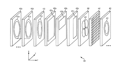
[0072] FIG. 4 illustrates a schematic view of an exemplary multi-layer
laminate panel
400 for use with a low-field MRI system, in accordance with some embodiments.
It should
be appreciated that laminate panel 400 is depicted as such to illustrate some
examples of
components that may be fabricated via laminate techniques. However, it should
be
appreciated that a laminate panel need not include all of the components
illustrated in FIG. 4,
and any one or more of the illustrated components may be omitted as desired.
That is, a
laminate panel may include any one or combination of the exemplary layers
illustrated in
FIG. 4 to form any one or combination of components (or portions thereof) in
the laminate
panel. In addition, a laminate panel may include other layers not illustrated
in FIG. 4 (e.g.,
one or more layers for thermal management, one or more interconnect layers,
one or more
layers having control electronics or other electronic components, etc.).
[0073] The illustrated components (or any desired subset) may be formed
in one or
multiple layers, and separate components may be formed on layers shared with
other
components, or formed on separate layers independent from other components. To
simplify
illustration of a multi-layer panel (and the nearly limitless combination of
layers and
configurations thereof), the magnetic components illustrated in FIG. 4 are
shown
schematically without limitation on geometry of the magnetic components, or
the number of
layers on which they may be fabricated. As such, the exemplary layers
illustrated in FIG. 4
and described herein should be understood to represent either a single
laminate layer
composed of at least one non-conductive layer and at least one conductive
layer, or multiple
such laminate layers, each composed of one or more non-conductive layers and
one or more
conductive layers. Accordingly, unless otherwise specified, a layer refers to
one or more
laminate layers.
[0074] It should be further appreciated that the illustrations in FIG.
4 showing the
various components that may be fabricated within panel 400 are used to
generically represent
18
CA 3043063 2019-05-13
WO 2016/037025 PCT/US2015/048470
the respective component and are not intended to depict any particular
geometry or
configuration. The components illustrated in FIG. 4 may be patterned according
to any
desired geometry and configuration, as the techniques described herein for
integrating one or
more magnetic components within a laminate panel are not limited for use with
any particular
geometry, configuration or arrangement. Some examples of suitable geometries
that may be
utilized are discussed without limitation in further detail below.
[0075] As shown, exemplary laminate panel 400 includes a plurality of
Bo layers
(410a, 410b) having one or more Bo coils (411a, 411b) formed thereon. The Bo
coils are
configured to generate at least a portion of a Bo field for the low-field MRI
system when an
appropriate current is applied to the coil(s). In some embodiments, each Bo
layer includes
one or more turns of a conductive trace patterned on the conductive layer to
generate a
portion of a desired Bo field. As shown, layer 410a has patterned thereon a
coil 411a, which
may be patterned according to any desired geometry. For example, coil 411a may
be
patterned according to a generally circular geometry have one or more turns of
conductive
traces. Coil 411a may be electrically connected to coil 411b patterned on
layer 410b (e.g., by
a via between the layers), which also may be of any desired geometry (e.g., a
generally
circular coil having one or more turn of a conductor).
L00761 It should be appreciated that any suitable number of layers
having Bo coils
formed thereon may be interposed between and electrically connected to layers
410a and
410b (e.g., 1, 10, 20, 50 or more layers, etc), each having one or more
respective coils formed
thereon that, when energized with a suitable current, provides at least a
portion of a Bo field
configured for use in low-field MRI. It should be appreciated that each layer
may have a
single coil or multiple coils, and each coil may be patterned to have any
number of turns
formed thereon to achieve the magnetic and/or electric properties of a desired
coil design.
[0077] The inventors have recognized and appreciated that using
laminate techniques
to design and manufacture MRI components enables the fabrication of Bo coils
having
arbitrary geometries and configurations not practicable or possible using
conventional
techniques for manufacturing Bo coils for low-field MRI systems, allowing for
coil designs of
virtually any geometry, configuration and/or arrangement. According to some
embodiments,
at least some Bo layers on which one or more coils, or portions thereof, are
formed may be
patterned using different coil geometries than other layers to achieve a
desired Bo field.
Some Bo layers may have formed thereon one or more coils that can be
independently
controlled to tune the Bo field for different applications and environments,
or to adjust the Bo
19
CA 3043063 2019-05-13
WO 2016/037025 PCT/US2015/048470
field to calibrate or otherwise achieve a Bo field of desired strength and/or
homogeneity, as
discussed in further detail below.
[0078] The selection of a particular coil geometry or combination of
coil geometries
and the arrangement and distribution of the coils within a laminate panel may
depend, at least
in part, on a desired Bo field to be generated for use with low-field MRI
applications.
Additionally, one or more laminate layers having the same or different Bo coil
design may be
connected by one or more vias connecting the conductive traces on the multiple
layers. In
some embodiments, the locations of the vias may be selected to minimize their
effect on the
homogeneity of the resultant Bo field and/or to generally optimize one or more
electrical
properties of the energized coil. Non-limiting examples of Bo coil designs
that may be used
to form, at least in part, a Bo magnet for use in low-field MRI, are described
in further detail
below.
[0079] Because laminate techniques are capable of patterning electrical
conductors
with such high precision and accuracy, a Bo magnet (or any portion thereof)
may be
fabricated in laminate panel form reliably and with high fidelity in
accordance with the
design specifications for a particular Bo magnet to achieve a Bo field of
desired strength and
homogeneity. Additionally, the ability to distribute one or more Bo coils
forming a Bo
magnet (or a portion thereof) over multiple layers of a laminate panel allows
for optimizing
the parameters of the Bo magnet to generate a desired Bo field in a manner not
possible using
conventional techniques for producing a Bo magnet. Simulations may be used to
select
among numerous geometries, configurations and/or arrangements (e.g., the
position,
geometry or other properties of electrical conductors on each layer
contributing the Bo field
may be generally optimized) to produce a desired Bo field. The resulting
design may then be
precisely and accurately fabricated using suitable laminate techniques.
[0080] According to some embodiments, one or more laminate layers may
include
passive magnetic component(s), such as one or more layers patterned with
magnetic
materials, to facilitate the generation of a desired Bo field with reduced
power requirements,
or to produce a higher Bo field using the same power requirements as needed
without the use
of magnetic materials. For example, laminate panel 400 may include one or more
laminate
layers 415 patterned with ferrous, or other magnetic materials, arranged to
form a magnetic
component 416 that contributes to the magnetic field generated by one or more
Bo coils to
achieve a desired Bo field. Because such magnetic materials produce or tailor
a magnetic field
without needing a power source to provide current to produce a magnetic field,
a desired Bo
CA 3043063 2019-05-13
WO 2016/037025
PCT/US2015/048470
field may be produced with reduced power requirements. Additionally, because
magnetic
materials can be used to produce a higher Bo field without a corresponding
increase in power
requirements, magnetic materials may facilitate the construction of a low-
field MR1 system
having a higher Bo field, potentially exceeding .2T (e.g., between .2T and
.5T).
[0081] Magnetic component(s) 416 formed on one or more layers 415 may
include
any one or combination of materials having relatively high magnetic
permeability (II) to
assist in producing or tailoring a Bo field of desired field strength and/or
homogeneity.
Magnetic component(s) 416 may be formed by one or more patterned layers,
provided as a
sheet, or other otherwise manufactured and incorporated within one or more
laminate layers
to produce a desired magnetic field. As discussed above, the use of passive
magnetic
components can reduce the power requirements needed to produce a given Bo
field. That is,
because a portion of a desired Bo can be produced passively (e.g., without
requiring a power
source to operate the components), the burden on the active magnetic
components (e.g., the
one or more a desired Bo coils) can be reduced. As a result, one or more Bo
coils can be
operated with reduced current to produce, in combination with magnetic
component(s) 16, a
Bo field having a desired field strength and/or homogeneity. Reducing the
power
requirements of the active magnetic components simplifies the cost and
complexity of the
power electronics driving the magnetic components, results in a corresponding
reduction in
the thermal output of the laminate panel, and also may otherwise ease the
constraints on the
active magnetic components in generating a Bo field of desired strength and/or
homogeneity.
[0082] As discussed above, a laminate panel may further comprise at
least one
conductive layer patterned to form one or more gradient coils, or a portion of
one or more
gradient coils, capable of producing or contributing to magnetic fields
suitable for providing
spatial encoding of detected MR signals when operated in a low-field MM
system. In the
example illustrated in FIG. 4, laminate panel 400 includes a plurality of
laminate layers
(420a, 420b, 420c) on which gradient coils (421a, 421b, 421c) are formed.
Layer(s) 420a
includes a conductive trace patterned to form all or a portion of a Z-gradient
coil 421a,
layer(s) 420b includes a conductive trace patterned to form all or a portion
of a Y-gradient
coil 421b, and layer(s) 420c includes a conductive trace patterned to form all
or a portion of
an X-gradient coil 421c. As discussed above, the depiction of gradient coils
421a, 421b and
421c in FIG. 4 is meant to generically represent gradient coils of any
suitable geometry using
any number and configuration of layers to provide the one or more desired
gradient coils.
21
CA 3043063 2019-05-13
WO 2016/037025 PCT/US2015/048470
[0083] As one non-limiting example wherein gradient coils are at least
partially
formed in a laminate panel (e.g., laminate panel 400), a Z-gradient coil may
be formed, at
least in part, in one or more layers using a generally circular geometry and
an X-gradient coil
and a Y-gradient coil may be formed, at least in part, in one or more layers
using a generally
rectangular geometry such as via one or more conductors patterned as a grid
(e.g., similar to
the geometry schematically illustrated in HG. 1). The conductors for the
gradient coils may
be distributed across one or multiple layers in any combination as desired to
produce
integrated gradient coils, either with or without other magnetic components of
a low field
MRI system, and either sharing layers with other magnetic components and/or
patterned on
separate layers of a laminate panel.
[0084] In some embodiments of a laminate panel with both Bo coils and
gradient coils
for thereon, at least one layer of the laminate panel may include both Bo
coils (or a portion
thereof) and gradient coils (or a portion thereof) that may be selectively
controlled to provide
desired magnetic field characteristics for low-field imaging applications. In
some
embodiments, at least a portion of the same conductive trace on a layer of a
laminate panel
may function as a Bo coil or as a gradient coil depending on how the coil is
operated.
According to some embodiments, a gradient coil may be distributed over
multiple layers and
according to some embodiments, multiple gradient coils (or portions thereof)
may be formed
in a single layer (e.g., one or more of X, Y and/or Z gradient coils), as the
techniques
described herein are not limited to any particular manner of distributing
magnetic
component(s) over multiple layers of a laminate panel or multiple laminate
panels. It should
be appreciated that one or more gradient coils fabricated using laminate
techniques may be
utilized in connection with one or more other magnetic components fabricated
using laminate
techniques (e.g., by integrating the one or more gradient coils in a shared or
separate laminate
panel), or may be utilized in connection with one or more other magnetic
components
fabricated using conventional techniques as part of a low field MRI system.
[0085] As also discussed above, a laminate panel may further comprise
at least one
conductive layer patterned to form one or more transmit and/or receive coils,
or a portion of
one or more transmit and/or receive coils, configured to stimulate MR response
by producing
a Bi excitation field (transmit) and/or to receive emitted MR signals
(receive) when operated
in conjunction with the coils configured to produce a Bo field and
corresponding gradient
fields. Such a laminate panel may incorporate single transmit and/or receive
coils (or
portions thereof) or multiple transmit and/or receive coils (or portions
thereof) for performing
22
CA 3043063 2019-05-13
WO 2016/037025 PCT/1JS2015/048470
single channel or parallel MRI. In the example illustrated in FIG. 4, laminate
panel 400
includes layer(s) 430 on which all or a portion of a transmit/receive coil 431
is formed.
[0086] Any suitable geometry may be used to pattern the
transmit/receive coil or set
of transmit/receive coils. For example, in some embodiments, a spiral-shape
conductor may
be patterned in one or more layers to form one or more transmit/receive coil
(or portions
thereof). According to some embodiments, a substantially rectangular geometry
may be
utilized to fabricate one or more transmit and/or receive coils using laminate
techniques.
According to some embodiments in which different coils are used for transmit
and receive,
transmit and receive coils may be formed in one or more layers using different
respective
geometries. In some embodiments, multiple layers and/or multiple laminate
panels may be
used to collectively form a transmit/receive coil and/or set of
transmit/receive coils for use in
a low field MRI system. It should be appreciated that one or more
transmit/receive coils
fabricated using laminate techniques may be utilized in connection with one or
more other
magnetic components fabricated using laminate techniques (e.g., by integrating
the one or
more other magnetic components in a shared or separate laminate panel), or may
be utilized
in connection with one or more other magnetic components fabricated using
conventional
techniques as part of a low field MRI system.
[0087] A laminate panel may further comprise at least one conductive
layer patterned
to form one or more electromagnetic shields arranged to prevent
electromagnetic energy from
the environment and/or generated from components of the MRI system from
disturbing the
magnetic fields generated by the MRI magnetics and/or for otherwise shielding
the apparatus
from electromagnetic interference. In the example illustrated in FIG. 4,
laminate panel 400
includes layer(s) 440 used to provide electromagnetic shielding. Although only
a single
shielding layer is shown, it should be appreciated that any suitable number of
shielding layers
may be used in any different number of locations, and the patterned conductive
layer(s)
forming one or more shields may be formed in separate layers or formed on
layers on which
other components are formed (e.g., patterned in electrical isolation on unused
portions of one
or more laminate layers on which other magnetic components or portions of
other magnetic
portions are formed. Shielding layer(s) 440 may be formed by patterning a
conductor mesh
in one or more layers of laminate panel 400, though it should be appreciated
that shielding
may be provided using any suitable conductor pattern to form any desired
geometry, which
geometry may be selected based on where the respective shielding is provided
and/or
23
CA 3043063 2019-05-13
WO 2016/037025 PCT/US2015/048470
characteristics of the electromagnetic interference the particular shielding
is employed to
suppress or eliminate.
[0088] Electromagnetic shielding may be configured to provide active
shielding or
passive shielding, and embodiments are not limited in this respect. In some
embodiments,
shielding formed on multiple layers of a laminate panel are connected using
one or more vias.
Accordingly, at least some shielding for a low field MRI system may be
integrated into one
or more laminate panels in which one or more magnetic components are
fabricated, either on
one or more separate layers or on one or more layers on which another magnetic
component
(or portion thereof) is formed. Electromagnetic shielding may include static
or dynamic
shielding of magnetic fields, electric fields, or both.
[0089] Shim coils arranged to facilitate the production of desired
magnetic fields may
also be patterned on one or more layers of a laminate panel. According to some
embodiments, a laminate panel may comprise at least one conductive layer
patterned to form
one or more shim coils, or a portion of one or more shim coils, arranged to
produce or
contribute to magnetic field(s) and adapted to improve the homogeneity of the
Bo field
generated by one or more Bo coils, to otherwise improve the Bo field within a
given field of
view and/or to counteract other magnetic fields that negatively impact the Bo
field. In the
example illustrated in FIG. 4, laminate panel 400 includes layer(s) 450 on
which one or more
shim coils 452 (or portions thereof) are formed. For embodiments that include
a laminate
panel with at least one Bo coil and at least one shim coil, the at least one
shim coil may be
formed by conductive layers shared with (but electrically isolated from) the
at least one Bo
coil (or portions thereof) or may be formed in one or more conductive layers
separate from
the at least one Bo coil (or portions thereof). As with the other magnetic
components
discussed, shim coils fabricated using laminate techniques may be utilized
with other
components fabricated using laminate techniques (e.g., by integrating the shim
coils in a
shared or separate laminate panel) or utilized with other components
manufactured using
conventional techniques as part of a low field MRI system.
[0090] As discussed above, multiple low-field MRI components (or
portions thereof)
may be formed on a single layer (i.e., a single laminate layer) of a laminate
panel. That is,
multiple magnetic components or portions of multiple magnetic components may
be
patterned on the same conductive layer of a single laminate layer. For
example, the
conductive layer of a single laminate layer may be patterned to form one or
more Bo coils
24
CA 3043063 2019-05-13
WO 2016/037025 PCT/US2015/048470
(either forming or contributing to a complete Bo magnet) and one or more
gradient coils or
portion of one or more gradient coils.
[0091] As a further example, a single laminate layer of a laminate panel
may be
patterned to form all or a portion of a gradient coil and all or a portion of
a transmit/receive
coil. The gradient coil and the transmit/receive coil (or portions thereof)
may share at least
some conductive elements formed on the laminate layer, or the gradient coil
and the
transmit/receive coil (or portions thereof) may be formed separately on the
same laminate
layer (e.g., electrically isolated from one another). As another example, a
single laminate
layer of a laminate panel may be patterned to form all or a portion of one or
more Bo coils
and all or a portion of one or more shim coils used to tune the homogeneity of
the Bo field for
the low-field MRI system. The shim coil(s) and the Bo coil(s) (or portions
thereof) may share
at least some conductive elements formed on the laminate layer or the shim
coil(s) and the Bo
coil (or portions thereof) may be formed separately on the same laminate layer
(i.e.,
electrically isolated from one another). It should be appreciated that any
combination of
components (or portions thereof) may be similarly fabricated in one or more
shared laminate
layers as desired according to a specific design, as the aspects are not
limited in this respect.
[0092] The inventors have recognized and appreciated that some conductors
formed
on laminate panels in accordance with some embodiments may be configured to
perform
multiple functions typically characteristic of functions performed by separate
MRI
components. By repurposing the same conductors to perform different functions
and/or by
sharing laminate layers of a laminate panel between multiple components or
portions of
multiple components, the dimensions and costs associated with manufacturing a
laminate
panel may be reduced.
[0093] It should be appreciated that the order of the laminate layers of
laminate panel
400 shown in FIG. 4 is provided merely for illustration, and any suitable
ordering of layers
may be used. That is, when multiple magnetic components (or portions thereof)
are
integrated into a laminate panel, any ordering of the laminate layers may be
used to achieve a
desired sequence of the integrated magnetic components. In some embodiments,
the
configuration of the layers and components formed thereon may be selected
based, at least in
part, on design considerations for optimizing one or more system and/or
imaging parameters
including, but not limited to, power consumption, gradient linearity, Bo field
homogeneity,
gradient strength, RF strength, thermal considerations, etc. For example, in
some
embodiments, one or more layers comprising all or a portion of one or more Bo
coils may be
CA 3043063 2019-05-13
WO 2016/037025 PCT/US2015/048470
located as the innermost layer(s) of the laminate panel to reduce power
consumption of the
low-field MRI system. In some embodiments, one or more outer layers of the
laminate panel
may be patterned to provide electromagnetic shielding. Accordingly, any
ordering of layers
of a laminate panel may be used. as the techniques described herein are not
limited for use
with any particular configuration in this respect.
[0094] As discussed above, though laminate panel 400 is shown as having
fabricated
therein all or portions of Bo coils, gradient coils, transmit/receive coils,
shim coils, and
electromagnetic shielding to illustrate exemplary components that may be
fabricated using
laminate techniques, a laminate panel may include any one or combination of
components, or
desired portions thereof. In some embodiments, at least some of the exemplary
components
are provided separate from laminate panel(s) (e.g., using conventional
manufacturing
techniques for those components). For example, some embodiments include
laminate
panel(s) having one or more Bo coils formed thereon, with other components of
the low-field
MRI system being provided separate from the laminate panel(s). Other
embodiments
include laminate panels having one or more gradient coils formed thereon, with
other
components of the low-field MRI system being provided separate from the
laminate panels.
For example, in such embodiments, the main magnetic field Bo for the low-field
MRI system
may be manufactured using conventional techniques (e.g., as described above in
connection
with the bi-planar Bo coil architecture in FIG. 1), and the transmit/receive
coil may be
provided by a helmet-based and/or surface-based coil placed around or near the
object to be
imaged. In other embodiments, laminate panels may have formed thereon both one
or more
Bo coils and one or more gradient coils (or portions thereof), with other
components of the
low-field MRI system being produced separate from the laminate panel(s).
[0095] Accordingly, it should be appreciated that laminate panels
manufactured in
accordance with techniques described herein may include any suitable number of
layers on
which any one or combination of low-field MRI components (or portions thereof)
are formed,
and such laminate panel(s) may be utilized in connection with any number of
other laminate
panel(s) or any one or combination of other components produced using other
techniques, as
the aspects are not limited in this respect. According to some embodiments, a
hybrid
approach may be used wherein one or more magnetic components are implemented
with a
portion being fabricated using laminate techniques and a portion produced
using conventional
techniques.
26
CA 3043063 2019-05-13
WO 2016/037025 PCT/US2015/048470
[0096] As discussed above, magnetic components may be fabricated, in
part or in full,
by distributing portions of the magnetic component(s) over a plurality of
layers of a laminate
panel in any number of different configurations. FIG. 5 illustrates a multi-
layer laminate
panel 500 having a Bo coil fabricated therein, in accordance with some
embodiments. FIG. 5
shows some examples of how portions of a Bo coil may be distributed across
multiple layers
of a laminate panel to produce, when energized, a magnetic field contributing
to a Bo field
suitable for performing low-field MRI. While the example layers schematically
illustrate
portions of a Bo coil fabricated therein, each layer may (but need not)
include other
components, including other magnetic components (e.g., one or more gradient
coils,
transmit/receive coils, shim coils, etc.), as discussed in further detail
below.
[0097] Exemplary laminate panel 5 comprises fourteen laminate layers
over which
portions of a Bo magnet are distributed by patterning the respective
conductive layers
accordingly. In FIG. 5, the conductive patterns provided on example layers are
illustrated by
a generally circular coil, the width of which denotes in a representative
manner the number of
turns forming the respective coil. The coils are represented with solid and
dashed lines to
indicate that, when energized, current through coils represented with solid
lines flows in the
opposite direction as current through coils represented with dashed lines
(e.g., clockwise
versus counter-clockwise, or vice versa). Example laminate panel 500 comprises
coils 510A,
510B, 510C, 510D, 510E, 510E, 510F and 510G fabricated thereon and
distributed, by way
of example only, in the manner described below.
[0098] Each of the exemplary layers 1-14 in FIG. 5 have fabricated
thereon a coil
510A comprising a plurality of turns, for example, twenty turns of conductive
traces each.
That is, as shown in the depicted layers, each of the fourteen layers may be
patterned to form
a respective outer coil having twenty turns of conductive traces. Each coil
510A may be
connected to coil 510A in the subsequent layer using a one or more vias
between the layers
(e.g., plated through-holes, pins, or other suitable conductive vias).
Alternatively, one or
more of the outer coils 510A may be electrically isolated from other coils
510A and may, for
example, be configured to be independently energized (e.g., one or more of
coils 510A may
be utilized as a shim coil). Each of the first six layers (e.g., Layers 1-6
illustrated in FIG. 5)
consist of outer coil 510A with respect to the integrated Bo coil, though
other components
(including other magnetic components) may be fabricated thereon in addition.
[0099] Each of layers 7-14 also have fabricated thereon a respective
coil 510B, which
as denoted by the dashed lines, may conduct current in an opposite direction
as coils 510A
27
CA 3043063 2019-05-13
WO 2016/037025 PCT/US2015/048470
when operated. In example laminate panel 500, each coil 510B includes a number
of turns
less than the number of turns in coils 510A formed on respective layers. As
indicated by the
decreasing line width used to represent coils 510B, the number of turns of
conductive traces
forming the respective coil may also decrease (or otherwise vary) across the
layers on which
the coils are distributed. For example, coils 510B in layers 7 and 8 may
comprise 11 turns of
conductive traces each, coils 510B fabricated in respective layers 9-11 may be
formed with
turns, coil 510B fabricated in layer 12 may be formed with 9 turns, and coils
510B
fabricated in respective layers 13 and 14 may be formed with 8 turns. It
should be
appreciated that the turn configuration is exemplary. and that the number of
turns and how
the number of turns vary (or remain constant) are not limited in any respect.
[0100] Each of layers 7-14 also have fabricated thereon a respective coil
510C, which
as denoted by the solid lines representing the coils, may conduct current in
the same direction
as coils 510A when operated. In example laminate panel 500, each coil 510C
includes a
number of turns less than the number of turns forming coils 510B in the
respective layer,
which number may vary or remain the same across laminate layers on which coils
510C are
patterned. For example, coils 510C fabricated in respective layers 7-10 may be
formed with
6 turns, coil 510C fabricated in layer 11 may be formed with 5 turns, and
coils 510C
fabricated in respective layers 12-14 may be formed with 4 turns. However,
this arrangement
is merely exemplary and the number of turns and how they vary (or remain
constant) are not
limited by this example arrangement.
[0101] Each of layers 7-11 also have fabricated thereon a respective coil
510D and a
respective coil 510E, each of layers 7-9 have fabricated thereon a respective
coil 510F, and
each of layers 7 and 9 have fabricated thereon a respective coil 510G and a
respective coil
510H. In the example illustrated in FIG. 5, successive coils alternate the
direction in which
they conduct current when operated, and each successive coil includes a number
of turns of
conductors less than the preceding coil. However, this configuration is merely
exemplary
and the direction in which current is conducted, the number of turns in each
coil, and the
number of coils on each layer of a laminate panel may be selected as desired
to produce or
contribute to a Bo field for low field MRI.
[0102] As discussed in connection with coil 510A, the conductors forming
the
exemplary coils illustrated in FIG. 5 may be connected together intra-layer
(as discussed in
further detail below) and/or connected inter-layer using conductive vias
between the layers.
Furthermore, one or more of the coils illustrated in FIG. 5 may be patterned
in isolation and
28
CA 3043063 2019-05-13
WO 2016/037025 PCT/US2015/048470
capable of being independently energized. In this manner, such coils may be
used as shim
coils that can be operated as needed to improve the homogeneity of the
resulting Bo field in a
given environment or under given loading conditions (e.g., during calibration
of the low-field
MRI system).
[0103] .. As discussed above, coils provided in a same laminate layer may be
configured such that, when operated, current flows in different directions in
different
respective coils. For example, one or more coils patterned on a given laminate
layer may
conduct current in the opposite direction of one or more other coils patterned
in the same
laminate layer. FIG. 6A illustrates an exemplary layer 605 of a laminate panel
on which a Bo
coil is patterned (e.g., layer 605 may be similar to layer 12 illustrated in
FIG. 5). Layer 605
comprises coils 610A, 610B and 610C, each having a plurality of turns of a
conductive trace
(e.g., 20 turns, 10 turns and 5 turns, respectively). FIG. 6B illustrates
region 645 indicated in
FIG. 6A enlarged to show further detail regarding the conductive trace or
track patterned on
layer 605.
[0104] .. As illustrated in FIG. 6B, coils 610A, 610B and 610C are formed by a
single
conductive trace 615 patterned such that when electrical current is provided
to conductive
trace 615, current is conducted in alternating counter-clockwise and clockwise
directions with
respect to coils 610A, 610B and 610C. In particular, coil 610A conducts
current in a counter-
clockwise direction, coil 610B conducts current in a clockwise direction and
coil 610C
conducts current in a counter-clockwise direction. It should be appreciated
that conductive
trace 615 may be patterned to implement any desired configuration with respect
to the
direction in which current is conducted. For example, layers on which multiple
coils are
fabricated may be patterned such that current is conducted in the same
direction through each
coil, or the direction of current conduction may be changed through one or
more desired
coils, as techniques described herein are not limited for use with any
particular configuration
of conductors or direction of current flow.
[0105] FIGS. 6A and 6B also illustrate exemplary vias, of which via 675 is
labeled in
6B. These vias connect conductive traces patterned on one laminate layer with
conductive
traces patterned on one or more other laminate layers (e.g., as illustrated by
exemplary vias
shown in FIGS. 3A and 3B described above). Vias may be provided to connect
conductive
traces in adjacent laminate layers and/or may be provided through multiple
layers to connect
conductive traces patterned on any number of desired laminate layers.
Accordingly, the
conductive traces patterned on different layers of a laminate panel may be
connected in any
29
CA 3043063 2019-05-13
WO 2016/037025 PCT/US2015/048470
manner to produce desired circuitry for magnetic components (or other
electronic
components) fabricated within a laminate panel.
[0106] While the exemplary coils illustrated above in connection with FIGS.
5 and 6
are substantially circular and have substantially uniform concentric turns,
other geometries
and configurations can be utilized, as the techniques described herein are not
limited for use
with any particular geometry or configuration. For example, FIGS. 7 and 8
schematically
illustrate non-limiting examples of Bo coil designs that may be realized using
the laminate
techniques described herein. Unlike Bo coil designs that can be practically
realized for low-
field MRI systems using conventional production techniques, which typically
involve
winding a square or circular conductor around a rigid support structure, other
designs may be
realized by virtue of the flexibility and precision of laminate processes. For
example,
conductive traces for a Bo coil formed using laminate techniques may be
fabricated and
patterned, generally speaking, according to any desired dimensions and
according to any
desired geometry. As such, the conductive paths can be fabricated having
relative
dimensions generally not feasible using conventional wire conductors, and can
be patterned
according to geometries that are not practical, if even possible, using
conventional
manufacturing techniques. As such, laminate techniques may facilitate the
manufacture of
more optimal coil designs, not only for the Bo magnet, but for other magnet
components as
well (e.g., gradient coils, transmit/receive coils, shim coils, etc.).
[0107] Moreover, because laminate techniques allow a coil to be distributed
over
multiple (and in some designs relatively numerous) layers, the dimensions,
position,
geometry, etc. of the portion of the coil in each given layer may be selected
to generally
optimize the resulting magnetic field. For example, the inventors have
developed simulations
to vary one or more parameters of the conductive pattern on each layer to
determine a
generally optimal solution regarding any one or combination of conductor
dimension,
position, geometry, number of turns, and/or any other parameter(s) of the
conductive pattern
on each layer that impacts the resulting magnetic field. Different MRI
applications may have
different optimal solutions such that laminate techniques may be utilized to
design and
implement low-field MRI systems tailored for particular MRI applications.
[0108] FIGS. 7A-7C illustrate spiral Bo coil designs comprising a plurality
of turns,
which may for example, be patterned on a single layer of a laminate panel or
distributed over
multiple laminate layers and connected using appropriately placed vias. FIG.
7A illustrates a
relatively wide spiral trace of conductive material patterned on one or more
laminate layers.
CA 3043063 2019-05-13
WO 2016/037025
PCT/US2015/048470
FIG. 7B shows a spiral Bo coil design wherein the width of the conductive path
is thinner
than the conductive path illustrated in FIG. 7B, but the number of turns is
greater. FIG. 7C
shows a spiral Bo coil design having a non-uniform density of turns of the
spiral (i.e., the
spiral geometry becomes tighter as it moves inward). Using one or more
variable density
spiral Bo coils may reduce the amount of power required to produce a desired
strength Bo
field compared to a given circular coil designs. Manufacture of such variable
spiral density
Bo coils are typically impractical or not feasible using conventional wire-
wrapping
techniques. It should be appreciated that other spiral-based Bo coil designs
are also possible
and the geometries and configurations illustrated herein are merely exemplary
of possible coil
designs.
[0109] FIGS. 8A-
8C illustrate concentric ring Bo coil designs comprising a plurality
of turns that may be patterned on a single laminate layer of a laminate panel
or distributed
over multiple laminate layers using appropriately placed vias. FIG. 8A
illustrates a plurality
of connected circular traces of conductor material formed on one or more
laminate layers and
having a uniform density with respect to the turns of the conductor. FIG. 8B
shows a Bo coil
design where both the number and density of the turns of the Bo coil formed on
the laminate
layer are increased compared to the design of FIG. 8A, while maintaining a
uniform density
of the turns. FIG. 8C shows a Bo coil design having a non-uniform density of
turns of the
concentric coils. It should be appreciated that other circular-based Bo coil
designs are also
possible, for example, the exemplary Bo coil configurations described above in
connection
with FIGS. 5, 6 and 10, and embodiments are not limited in this respect.
[0110] As
discussed in connection with FIG. 4, laminate techniques may be used to
produce gradient coils integrated within a laminate panel, either in part or
in full and/or alone
or in combination with one or more other magnetic components. Gradient coils
may be
patterned according to any desired geometry suitable for a particular
implementation. FIGS.
9A-9C illustrate exemplary x-gradient, y-gradient and z-gradient coils in
accordance with
some embodiments. For example, FIG. 9A illustrates an example of an x-gradient
coil 920A
that may be patterned on a single laminate layer or distributed over multiple
laminate layers
of a laminate panel. X-gradient coil 920A may, for example, be configured to
perform
frequency encoding. Similarly, y-gradient coil 920B may be patterned on a
single or multiple
laminate layers and, for example, be configured to provide phase encoding, and
z-gradient
coil 920C may be patterned on one or more laminate layers and, for example, be
configured
to provide localization of image slices. However, the gradient coils may be
arranged and
31
CA 3043063 2019-05-13
WO 2016/037025 PCT/US2015/048470
configured to perform any suitable spatial encoding. It should be appreciated
that patterns
illustrated in FIG. 9A-9C are merely exemplary and any configuration or
geometry may be
used to implement gradient coils for a low field MRI, as the techniques
described herein are
not limited to any particular design or configuration for implementing
gradient coils.
[0111] FIG. 10 illustrates an example wherein gradients coils are
fabricated on at
least some of the same layers as coils that form, at least in part, a Bo
magnet. In particular,
FIG. 10 illustrates six laminate layers of a laminate panel wherein x-gradient
coils 1020A, y-
gradient coils 1020B, and z-gradient coils 1020C are patterned in the same
layers as portions
of a Bo magnet (e.g., layers having patterned thereon one or more Bo coils or
portions
thereof). With respect to the Bo magnet, coils 1010A may be similar to coils
510A illustrated
in FIG. 5. The inventors have appreciated that regions of a laminate layer in
the center of
such Bo coils may be utilized to pattern one or more gradient coils, or
portions thereof. For
example, x-gradient coils 1020A may be patterned on layers 1000A and 1000B, y-
gradient
coils 1020B may be patterned on layers 1000C and 1000D, and z-gradient coils
1020C may
be patterned on layers 1000E and 1000F along with Bo coils 1020A patterned on
respective
layers of the laminate panel. It should be appreciated that gradient coils may
be integrated in
a same laminate panel with Bo coils for a low-field MRI Bo magnet in other
ways, including
patterning gradient coils, in whole or in part, on at least some separate
laminate layers of the
laminate panel, as integrating multiple magnetic components in a laminate
panel is not
limited to any particular manner of doing so. By sharing layers between
magnetic
components, the number of layers may be reduced, thus reducing the cost of
manufacturing a
laminate panel.
[0112] As also discussed above in connection with FIG. 4, one or more
shim coils
may be fabricated within a laminate panel along with one or more other
magnetic
components of a low field MRI system. FIGS. 11A and 11B illustrate example
shim coils
that may be patterned on one or more layers of a laminate panel to produce a
magnetic field
to contribute to or assist in providing a B0 field of desired strength and
homogeneity. As one
non-limiting example, shim coil 1150A may be patterned in one or more laminate
layers to
produce, when energized, a corresponding magnetic field. Coil 1150A may be
configured to
be independently energized by. for example, electrically isolating coil 1150A
from other
active components provided within the same laminate panel or the same laminate
layer so
that coil 1150A can be powered separately. Coil 1150B illustrated in FIG. 11B
shows a
different exemplary geometry for providing a shim coil integrated within a
laminate panel.
32
CA 3043063 2019-05-13
WO 2016/037025 PCTIUS2015/048470
Similar to shim coil 1150A, shim coil 1150B may be configured to be
independently
operated.
[0113] It should be appreciated that shim coils may be provided in any
manner and
configuration to contribute magnetic fields that facilitate the production of
a Bo field of
desired strength and homogeneity. For example, coil 1150A and/or coil 1150B
may be
patterned on a single layer or distributed across multiple layers, and each
coil may be
patterned on a layer alone or may share one or more layers with one or more
other
components, or portions thereof. Moreover, any number of shim coils having any
desired
geometry may be fabricated within a laminate panel, as the aspects are not
limited in this
respect. According to some embodiments, one or more shim coils are fabricated
within a
laminate panel separate from other magnetic components of a low field MRI
system.
According to some embodiments, shim coils may be provided in different
geometries and/or
locations such that different combinations of shims coils may be selectively
activated in
response to a given environment in which the system is being operated. The
ability to
dynamically choose a combination of shim coils to operate may facilitate the
production of
low field MRI systems capable of being deployed in a transportable or cartable
fashion. As
discussed above, shim coils that contribute to a Bo field (e.g., to improve
homogeneity), when
operated, are Bo coils since they in fact do contribute to the Bo field of the
MRI system.
[0114] According to some embodiments, one or more passive shims are
utilized to
produce a magnetic field to contribute to a Bo field of desired strength and
homogeneity. As
discussed above in connection with FIG. 3, magnetic materials may be utilized
to produce
magnetic fields without requiring a source of power to do so. Accordingly, one
or more
layers patterned with magnetic materials may be provided as passive shims to
assist in
producing the desired Bo field. As with other components described herein,
passive shims
may be provided in any number, arrangement and geometry, and may be patterned
on a
single or multiple layers, either alone or on layers shared with one or more
other components,
as the aspect relating to providing passive shims are not limited to any
particular
configuration, geometry or arrangement. Passive shims may be provided using
separate shim
elements comprised of magnetic materials of any desired geometry. Such shim
elements may
be incorporated into a laminate panel by affixing the elements to the panel
(e.g., using an
adhesive or by other means of attachment) at desired locations and/or such
shim elements
may be arranged separate from the laminate panel at desired locations, as the
aspects are not
33
CA 3043063 2019-05-13
WO 2016/037025 PCT/US2015/048470
limited to any particular manner of incorporating one or more passive shims
into a low-field
MRI system.
[0115] As discussed in the foregoing, laminate techniques may be used
to produce
magnetic component(s) in any number of different combinations and
configurations. For
example, the inventors have further recognized and appreciated that laminate
panel
techniques may also be used to implement a low-field MRI system according to
solenoid Bo
coil designs, wherein the Bo field generated is oriented along the axis
through the center of a
solenoid coil, a design frequently used to implement high-field MRI systems.
In particular,
according to some embodiments, one or more solenoid-based coils may be formed
on a
plurality of connected laminate panels arranged to create a field of view
through the center of
the one or more solenoid-based coils in which an object to be imaged may be
positioned.
[0116] FIG. 12 illustrates a magnetic apparatus 1200 comprising a
plurality of
laminate panels having magnetic components fabricated thereon, including a
solenoid Bo
magnet for use in a low-field MRI, in accordance with some embodiments. As
shown,
magnet apparatus 1200 comprises eight connected laminate panels forming an
octagonal tube
in which an object to be imaged may be placed. The solenoid magnet includes a
Bo coil 1210
formed by connecting a plurality of conductive segments patterned on each of
the laminate
panels. The laminate panels may be connected in any suitable way to ensure a
stable
connection between the conductive segments formed on adjacent laminate panels
(e.g., one or
more conductive adhesives, portions capable of being snapped together or
otherwise attached,
or any other suitable connectors may be used to make appropriate electrical or
mechanical
connection between adjacent laminate panels). When connected and energized
with a
suitable current, conductive segments patterned on the laminate panels form a
solenoid Bo ,
coil 1210 that generates a Bo field in the longitudinal (Z) direction of
magnetic apparatus
1200. It should be appreciated that the windings of Bo coil 1210 are schematic
to illustrate
how a solenoid coil can be implemented via a plurality of laminate panels.
[0117] In the example in FIG. 12, magnetic apparatus 1200 also includes
x-gradient
coils 1220a, 1220b formed on opposing laminate panels and configured to
generate a gradient
magnetic field in the x-direction and y-gradient coils 1230a, 1230b formed on
opposing
laminate panels and configured to generate a gradient magnetic field in the y-
direction.
Additionally, magnetic apparatus 1200 also includes z-gradient coils 1240a,
1240b having a
solenoid geometry similar to Bo coil 1210, but formed at the ends of magnetic
apparatus 1200
and configured to, for example, enable slice selection in the z-direction. The
geometry and
34
CA 3043063 2019-05-13
WO 2016/037025 PCT/US2015/048470
configuration of the gradient coils is exemplary and gradient fields may be
generated using
other patterns of conductors, as the aspects are not limited in this respect.
[0118] It should be appreciated that the laminate panels illustrated in
FIG. 12
represent laminate panels having any desired number of layers. That is, each
laminate panel
may include a single layer or each laminate panel may comprise multiple
layers, with each of
the multiple layers having formed thereon all or a portion of one or more low-
field MRI
components, as the desired magnetic components may be fabricated according to
any desired
configuration. For example, Bo coil 1210 may be formed by not only connecting
conductive
segments on multiple laminate panels as shown in FIG. 12, but by also
connecting conductive
segments formed in multiple layers of each laminate panel.
[0119] Because the laminate techniques described herein for
manufacturing
components of a low-field MRI system are highly configurable, any desired
geometry and/or
size of conductive segments may be used to provide a magnetic apparatus
according to a
desired design, and the configuration and arrangement illustrated in FIG. 12
is provided
merely to illustrate an example in accordance with some embodiments. For
example,
laminate panels can be formed to any size and shape and connected together to
create a
desired geometry. As such, a laminate panel system may be produced that
conforms to
desired portions of the body and that have patterned thereon any one or
combination of
magnetic components and/or electronic components. According to some
embodiments, the
techniques described in connection with FIG. 12 may be used to construct a
laminate-based
system for imaging desired anatomy, wherein any desired combination of
magnetic
components may be fabricated on a series of connected laminate panels having a
geometry
formed around and configured to accommodate the desired anatomy. For example,
a series
of connected laminate panels may be constructed to image the head, as
discussed in further
detail in connection with FIGS. 22A-22C described below.
[0120] As discussed in the foregoing, laminate techniques may be
utilized in
numerous ways to produce one or more magnetic components of a low-field MRI
system.
An exemplary low-field MRI system utilizing laminate panels produced using
laminate
techniques described herein is illustrated in FIG. 13. In particular, FIG. 13
schematically
illustrates components of a low-field MRI system 1300 in which laminate panels
1310a,
1310b having one or more magnetic components of the low-field MRI system
fabricated
thereon are utilized. It should be appreciated that the bi-planar arrangement
of magnetic
components illustrated in FIG. 13 is similar to that shown in FIG. 1, but with
one or more
CA 3043063 2019-05-13
WO 2016/037025 PCT/US2015/048470
magnetic components provided via laminate panels 1310a, 1310b using laminate
techniques
rather than producing the magnetic components using conventional techniques.
For example,
one or more magnetic components produced using conventional techniques such as
Bo coils
110a, 110b and/or gradient coils 120a, 120b in FIG. 1 have been replaced with
integrated
magnetics in laminate panels 1310a, 1310b.
[0121] In the exemplary system illustrated in FIG. 13, laminate panel
1310a may
integrate one or more B0 coils and/or one or more gradient coils to form one -
side" of a bi-
planar coil arrangement, and laminate panel 1310b may similarly integrate one
or more Bo
coils and/or one or more gradient coils to form the other "side" of the hi-
planar arrangement.
As such, a bi-planar Bo magnet may be produced using laminate techniques that,
when
operated, generates a Bo field between the panels suitable for performing low-
field MRI.
Gradient coils for spatially encoding emitted MR signals may also be
integrated within
laminate panels 1310a, 1310b using laminate techniques. It should be
appreciated from the
foregoing that other magnetic and/or electronic components may be fabricated
within
laminate panels 1310a, 1310b including, but not limited to, one or more
transmit/receive
coils, one or more shim coils, shielding, power electronics, thermal
dissipation components,
etc.
[0122] As discussed above, providing integrated magnetics in laminate
panel form
may avoid one or more drawbacks of conventional manufacturing techniques
including, but
not limited to, relatively difficult and sensitive coil winding and alignment,
post-production
alignment of magnetic components, portability, limitations on post-production
configuration
and calibration, etc. Furthermore, providing one or more magnetic components
integrated in
laminate panel form may also provide flexibility, reliability and/or
scalability advantages that
may simplify the design, manufacture and installation of low field MRI
systems. Integrated
magnetics using laminate techniques may offer further benefits including, but
not limited to,
flexibility of design with respect to geometry and configuration, the ability
to customize
magnetics for particular applications, reduced cost, increased portability
and/or compactness
of a low field MRI system.
[0123] It should be appreciated from the foregoing discussion that
laminate panels
(e.g., laminate panels 1310a, 1310b) may integrate any one or combination of
Bo coils,
gradient coils, transmit/receive coils, shim coils, and electromagnetic
shielding, and are not
limited for use with any particular one or combination of magnetic components
(or portions
thereof). Any one or more magnetic components that are not integrated therein,
may be
36
CA 3043063 2019-05-13
WO 2016/037025 PCT/US2015/048470
provided using any other available techniques (e.g., one or more magnetic
components may
be provided using conventional techniques for producing the respective
magnetic
component).
[0124] According to some embodiments, a magnetic component may be
produced
using a hybrid technique, wherein a portion of the magnetic component is
fabricated in
laminate panel form and a portion of the magnetic component is manufactured
using a
different technique. For example, FIG. 14A illustrates a hybrid design for a
Bo coil, in
accordance with some embodiments. The hybrid design includes a coil 1405 and a
laminate
panel 1410 having integrated therein coils 1410A, 1410B and 1410C. Coil 1405
may be a
wound coil as discussed above in connection with FIG. 1, or may be one or more
stacked
metal plates that, when energized, produces a magnetic field that contributes
to a Bo field
suitable for low field MRI. A coil formed by a wound conductor refers to a
coil produced by
winding a conductor, such as wire, to form an electromagnet, and is contrasted
by coils
produced using laminate techniques that instead pattern the conductor to form
the coil.
Similarly. coils 1410A, 1410B and 1410C patterned on layers of laminate panel
1410, when
energized, produce a magnetic field that contributes to a Bo field suitable
for low field MRI.
The example hybrid design illustrated in FIG. 14A may represent one side of a
bi-planar
design or a component or facet in any of the geometries described herein. As
such, a Bo
magnet may be constructed using laminate and non-laminate techniques to
produce a desired
Bo field suitable for performing low-field MRI.
[0125] It should be appreciated that laminate panel 1410 is illustrated
schematically
to be representative of any desired laminate panel having any number of coils
distributed over
any number of laminate layers. For example, laminate panel 1410 may include
one or more
BO coils (e.g., BO correction or shim coils), one or more gradient coils
and/or one or more
Tx/Rx coils, as the aspects are not limited in this respect. It should be
further appreciated that
laminate panel 1410 need not be sized as shown in FIG. 14A relative to coil
1405 and may be
of any size and positioned in any manner relative to coil 1405, as the hybrid
design illustrated
in FIG. 14A is merely an example of how a laminate panel may be used in
conjunction with
one or more coils formed using non-laminate techniques (e.g., a wound copper
coil, copper
plate coil, etc.) to generate a desired Bo field, desired gradient field
and/or desired RF field.
[0126] FIG. 14B illustrates a portion of a hybrid magnet, in accordance
with some
embodiments. Hybrid magnet 1400' comprises a coil 1405' configured to produce
a
magnetic field that contributes to a Bo field of a desired field strength
and/or homogeneity.
37
CA 3043063 2019-05-13
WO 2016/037025 PCT/US2015/048470
Coil 1405' may be a coil formed by a conductor (e.g., a wound copper
conductor, copper
plate, etc.) provided using a number of turns (e.g., approximately 10, 50,
100, 150, 200, 250,
500 or more turns) suitable for a particular design and/or desired field
strength, inductance,
resistance, power requirements, etc. Coil 1405' may be constructed to any
desired size. For
example, an exemplary coil 1405' may have an inner diameter ranging from 10 to
50 inches
and an outer diameter ranging from 15 to 80 inches. It should be appreciated
that these
ranges are for illustration only and coil 1405' may be constructed to be
larger or smaller than
the above provided exemplary ranges. Coil 1405' may be wound using ribbon
wire, circular
wire, square wire or any other suitable conductor and may be of any suitable
gauge. The
conductor may be copper, aluminum or any suitable material, as the aspects are
not limited in
this respect.
[0127] Hybrid magnet 1400' also includes laminate panel 1410' having a
plurality of
laminate layers with one or more magnetic components patterned respectively
thereon. For
example, according to some embodiments, laminate panel 1410' comprises a
plurality of
layers, each having a BO coil (e.g., a supplemental, con-ection or shim coil)
or portion thereof
patterned thereon that can be operated, in some cases selectively, to
contribute a respective
magnetic field to achieve a Bo field of desired strength and/or homogeneity.
Additionally or
alternately, laminate panel 1410' may comprise a plurality of layers, each
having a gradient
coil or portion thereof patterned thereon to produce a gradient magnetic field
in the x, y
and/or z direction. According to some embodiments, laminate panel 1410'
comprises one or
more layers patterned with an X- gradient coil, a Y-gradient coil and a Z-
gradient coil,
respectively, to provide gradient fields in three dimensions. Laminate panel
1410' may also
include other magnetic components (e.g., one or more radio frequency coils)
patterned on one
or more layers, as the aspects are not limited in this respect.
[0128] It should be appreciated that laminate panel 1410' may include
any one or
combination of magnetic components and/or electronic components fabricated
thereon using
any of the techniques described herein or using any other suitable technique.
For example,
laminate panel 1410' may include any of the types and combinations of magnetic
components illustrated in FIGS. 4, 5, 9A-C, 10 and 11A-B and described in the
accompanying description. Laminate panel 1410' may include other components as
well,
such as electronic components, shielding, passive elements, etc.
[0129] Laminate panel 1410' can be of any suitable geometry and
dimension. In
particular, an exemplary square laminate panel may have dimensions ranging
from 8" x 8" to
38
CA 3043063 2019-05-13
WO 2016/037025 PCT/US2015/048470
50" x 50". For example, an exemplary laminate panel may have dimensions of
approximately 16" x 16", 22" x 22" or any other suitable dimension for a given
design.
Exemplary non-square panels may be similarly dimensioned. Laminate panel 1410'
may be
fabricated with any number of layers (e.g., approximately 10, 20, 30, 50 or
more layers) on
which any desired magnetic component may be patterned, either in full or in
part. The
patterned layers may be formed from copper, aluminum or other suitable
material having a
thickness appropriate for the magnetic component(s) fabricated thereon and in
view of the
desired operating characteristics. For example, heavy copper (e.g., 5 ounce, 6
ounce, 7
ounce, 8 ounce, 10 ounce, etc.) may be used to pattern one or more magnetic
components
and/or extreme copper (e.g., 20 ounce, 25 ounce, 30 ounce, 50 ounce, etc.) may
be used to
pattern one or more magnetic components. However, other thicknesses of
conducting
material may be used, as the aspects are not limited in this respect. The
total thickness of the
laminate panel 1410' will depend, at least in part, on the number of layers
utilized, exemplary
thicknesses range from .1" to several inches.
[0130] Hybiid magnet 1400' may be a single-sided magnet or may be one
side of a
bi-planar magnet. In the latter case, the other side of the hybrid magnet may
similarly
comprise a coil 1405' and/or a laminate panel 1410' having one or more
magnetic
components patterned thereon. In some embodiments, the other side of the bi-
planar magnet
may not include a laminate panel. In this respect, the respective sides of a
bi-planar coil may
be identical in construction or may be different (e.g., may include the same
or different
components or number of components). As such, a bi-planar coil may be
symmetric or
asymmetric, as the aspects are not limited in this respect. A hybrid magnet
may be designed
to produce any desired field strength. For example, a hybrid magnet may be
configured to
produce a field strength of approximately 5 mT, 10 mT, 20 mT, 50 mT, 100 mT,
200 mT or
more.
[0131] FIG. 14C illustrates a hybrid magnet, in accordance with some
embodiments.
Hybrid magnet 1400" includes a coil 1405A, which may be similar to or the same
as coil
1405' described in connection with hybrid magnet 1400' in FIG. 14B, and
laminate panel
1410" which may be similar to or the same as laminate panel 1410' described in
connection
with hybrid magnet 1400' in FIG. 14B. In addition, hybrid magnet 1400"
includes coil
1405B, which also may be similar to or the same as coil 1405'. As a result,
hybrid magnet
1400' comprises two coils 1405A and 1405B that contribute magnetic fields to
facilitate
producing a Bo field of desired strength and/or homogeneity. As illustrated in
FIG. 14C, a
39
CA 3043063 2019-05-13
WO 2016/037025 PCT/US2015/048470
thermal management component 1430 is also provided between coils 1405A and
1405B to
remove heat from the coils and laminate panel 1410" during operation. Various
details of
thermal management component 1430 are described in a concurrently filed
application.
[0132] FIG. 14D illustrates hybrid magnet 1400" after the components
have been
affixed, attached or otherwise connected to one another. As shown, thermal
management
component 1430 is sandwiched between, and in thermal contact with, coil 1405A,
coil 1405B
and laminate panel 1410" to draw heat away from these components during
operation. For
example, a coolant (e.g., a cooling liquid or gas) may be circulated through
thermal
component 1430 via inlet 1470A and outlet 1470B to absorb heat and transfer it
away from
the magnetic components. As discussed above, hybrid magnet 1400" may be a
single-sided
magnet or may be one side of a bi-planar magnet. Some embodiments that utilize
hybrid
magnet 1400" in a bi-planar configuration are described in further detail
below. Table 1
illustrates an exemplary construction of a bi-planar magnet, in accordance
with some
embodiments.
Exemplary Hybrid Magnet
Field Strength 20 mT
Current 30.1 Amps
Total Power Dissipation -2.4 kW
Inductance 251 rnH
Wound Coils (4)
Conductor 1" x 0.016" ribbon wire
Turns 155
Inner Diameter 25.610"
Outer Diameter 31.5"
Thickness .1" to 8"
Insulation Mylar
Printed Circuit Board
Conductor 6 oz copper weight per layer (0.00084")
Shim Coils 20 layers
Gradient Coils 6 layers
Insulation Arlon 92ML and FR4 dielectric cores and
fill layers
Dimensions 16" x 16"
Total Thickness -.380"
Table 1
[0133] It should be appreciated that the construction details listed in
Table 1 are
merely exemplary and provided merely as illustration. A hybrid magnet may be
constructed
in numerous other ways to meet the design constraints of a given application
of an MRI
system. It should be further appreciated that the arrangement and geometry of
the coils
CA 3043063 2019-05-13
WO 2016/037025 PCT/US2015/048470
and/or laminate panel is not limited to those depicted. Furthermore, the
magnetic
components implemented using conventional manufacturing techniques and those
implemented using laminate panel techniques are not limited to the
combinations discussed
herein, as hybrid techniques may be used to produce the magnetic components of
a low-field
MRI system in any combination.
[0134] The inventors have further appreciated that the ability to
incorporate magnetic
components in laminate panels in any desired arrangement or combination allows
for
numerous different geometries (e.g., of different shapes and/or sizes) to be
realized to
facilitate developing low-field MRI apparatus tailored for particular MRI
applications.
Moreover, the inventors have recognized that producing magnetics using
laminate panels
may facilitate the manufacture of relatively low cost and/or cartable or
otherwise portable
low-field MRI systems. Furthermore, producing magnetics in panel form allows
for
manufacture of foldable and/or deformable MRI magnetic components, which
facilitates both
portability/cartability as well as the ability to construct MRI magnetics
specific for particular
MRI applications or to facilitate imaging specific portions of the body, as
discussed in further
detail below. Thus, producing MRI magnetics (or portions thereof) using
laminate panels as
described herein has the ability to fundamentally change how MRI can be used
in the medical
or clinical setting and revolutionize the MRI industry with far-reaching
impact, greatly
expanding the circumstances and situations for which MRI can be utilized.
[0135] Laminate panels may be produced and arranged in a variety of
geometries to
facilitate the construction of a desired low-field MRI system. For example,
FIG. 13
illustrates laminate panels arranged in a generally bi-planar arrangement. In
some
embodiments, laminate panels are arranged in different geometries, for
example, to produce
low-field magnetics configured for particular types of imaging and/or to image
particular
anatomy of interest. FIGS. 15A-C illustrate exemplary geometries in accordance
with some
embodiments. In FIGS. 15A-C, laminate panels are illustrated schematically and
it is to be
understood that the illustrated laminate panels generically represent laminate
panels having
any desired number of layers with any desired one or combination of magnetic
components
formed thereon in any desired arrangement. FIG. 15A illustrates an exemplary
laminate
panel geometry 1500A comprising four connected laminate panels arranged to
facilitate low-
field MRI of the head. The laminate panels are arranged and connected
generally to
accommodate the head so that desired portions of the head are within the field
of view of the
resulting Bo field. The laminate panels may be connected, attached or affixed
to one another
41
CA 3043063 2019-05-13
WO 2016/037025 PCT/US2015/048470
in any suitable way including, but not limited to, by an adhesive, by one or
more connectors,
by one or more hinges, and/or by any combination thereof, or any other
suitable method.
[0136] In geometry 1500A, one or more of the laminate panels
illustrated integrate
magnetics components of a low-field MRI system in any of the various
combinations
discussed herein. For example, in one implementation, each of laminate panels
1510A and
1520A may comprise at least one layer having formed thereon all or a portion
of a Bo coil
used to generate a Bo field for a low-field MRI system. In such an
implementation, the pair
of panels 1510A, 1520A may be arranged in the bi-planar geometry previously
described
with respect to FIG. 13, and sized to provide a field of view that
accommodates the head.
Laminate panels 1530A and 1540A may include one or more other components of
the low-
field MRI system (e.g., one or more gradient coils, transmit received coils,
shim coils, etc.) or
themselves may include all or a portion of a Bo coil to contribute to the
generation of a
desired Bo field. Adding additional Bo coils may allow for the relaxation of
the power
requirements for each Bo coil without compromising Bo field strength or
homogeneity.
Alternatively, one or both of panels 1530A and 1540A may not include any low-
field MRI
magnetic components, but may be fabricated to include supporting electronics,
such as power
or control electronics, may include thermal management components, shielding
and/or may
be provided for structural support.
[0137] It should be appreciated that the geometry illustrated in FIG.
15A is exemplary
and other arrangements are possible. For example, the panels may be
dimensioned to
accommodate the head such that the person being scanned faces one of the side
panels (e.g.,
panels 1510A or 1520A). Alternatively, a further panel connected to at least
one of panels
1510A, 1520A, and 1530A may be included to fully or partially enclose an
object (e.g., a
patient's head) to be imaged. Such a geometry provides an additional laminate
panel directly
opposed to panel 1540, which may be used to form one or more low-field MRI
components
thereon. In some embodiments, at least one of the laminate panels may comprise
or have
mounted thereon a visual display that enables a person being imaged to view
visual images
(e.g., pictures or video). Any suitable visual display including, but not
limited to, a liquid
crystal display, may be used for this purpose.
[0138] The general configuration illustrated in FIG. 15A can also be
used in
conjunction with a helmet comprising transmit/receive coils, for example, any
of various
form fitting helmets having generally spiral shaped coils formed on or within
the helmet to
provide a Bi field according to a desired acquisition sequence and to detect
MR signals
42
CA 3043063 2019-05-13
WO 2016/037025 PCT/US2015/048470
emitted in response. The laminate panels forming magnetic components of a low-
field MRI
system (e.g., a Bo magnet, gradient coils, etc.) may be constructed to
accommodate the
helmet such that the wearer of the helmet can be positioned inside the field
of view of the Bo
field generated when the laminate panel(s) are operated. Alternatively,
laminate panel(s)
having magnetic components for generating a Bo field and corresponding
gradient fields may
be integrated with a helmet having transmit/receive coils (e.g., a helmet
wound with
appropriate transmit/receive coils) to form the magnetics of a single
generally integrated head
scanner for low-field MRI.
[0139] FIG. 15B illustrates a further exemplary arrangement of panels
dimensioned,
for example, to accommodate other anatomy. As shown, laminate panels 1510B,
1520B,
1530B and 1540B are arranged to form an open-ended rectangular tube. The
relative
dimensions may be selected to allow a person to place all or a portion of an
extremity or
appendage (e.g., a hand, a foot, an arm, a leg, etc.) within the field of view
of the magnetic
field generated. It should be appreciated that the magnetic components may be
fabricated in
laminate panel form using any one or combination of configurations discussed
herein.
Furthermore, the laminate panels in FIG. 15B may be dimensioned to accommodate
any
desired anatomy (or other object), including increasing the size of the panels
and relative
dimensions to accommodate the torso or whole body of a person being imaged. It
should be
further appreciated that laminate panels fabricated with one or more magnetic
components
may be arranged in other configurations and geometries to produce, at least in
part, a desired
general purpose low-field MRI system, or a system configured for imaging
particular objects
or anatomy and/or to facilitate particular imaging applications, as discussed
in further detail
below.
[0140] FIG. 15C illustrates a planar configuration, in accordance with
some
embodiments. In particular, planar geometry 1500C illustrated in FIG. 15C may
be realized
by a single laminate panel 1510C having formed thereon one or more magnetic
components
for producing a Bo field suitable for low-field imaging of objects placed
proximate laminate
panel 1510C. Planar geometry 1500C facilitates, for example, performing low-
field MRI in
circumstances wherein the object being imaged cannot be conveniently placed
within or
between multiple panels and/or where multiple panel geometries are otherwise
inconvenient
or unnecessary, or a further reduced cost solution is desirable. Laminate
panel 1510C may be
sized as appropriate to produce a generally hand-held device that can be held
proximate an
object being imaged (e.g., near a particular portion of the anatomy for which
low-field MRI is
43
CA 3043063 2019-05-13
WO 2016/037025 PCT/US2015/048470
desired). Alternatively, laminate panel 1510C may be sized so that a patient
stands or sits
next to the laminate panel to perform low-field MRI. It should be appreciated
that laminate
panel 1510C may be produced in any desired size and/or shape to produce a
planar geometry
device for particular imaging applications (e.g., tailored for imaging
particular anatomy or
portions of anatomy), as the aspects are not limited in this respect.
[0141] The techniques described herein may be used to produce magnetic
components for a low-field magnetic resonance system configured to generate a
Bo field of a
given field strength (e.g., a field strength of less than or equal to
approximately .2T, less than
or equal to approximately .1T, less than or equal to approximately 50mT, less
than or equal to
approximately 20mT, less than or equal to approximately 10mT, etc). In some
embodiments
(e.g., embodiments that include ferromagnetic augmentation to increase field
strength), the Bo
field of the low-field MRI system could potentially exceed .2T.
[0142] As discussed above, the inventors have recognized that laminate
techniques
may be utilized to produce magnetics for low-field MRI systems. To describe
additional
aspects, further detail is provided in connection with an exemplary low-field
MRI system.
Briefly, referring back to FIG. 13, low-field MRI system 1300 further
illustrates a number of
other components that operate in conjunction with the magnetic apparatus to
facilitate low-
field MRI. In particular, exemplary low-field MRI system 1300 also comprises
console 1330,
which may include one or more processors programmed to generate MRI pulse
sequences
used to acquire data using low-field MRI system 1300 and/or console 1330 may
be
configured to perform any other suitable operation. In some embodiments,
console 1330 may
be configured to receive MR data detected by one or more receive coils (which
may be
integrated within laminate panels 1310a, 1310b, or provided in a different
manner such as via
a helmet worn by the user, as discussed in further detail below) and provide
the received MR
data to workstation 1360 for processing the data (e.g., to reconstruct one or
more MRI
images). Low-field MRI system 1300 also includes power management system 1340,
which
includes electronics to provide operating power to one or more components of
the MRI
system. For example, as discussed in more detail below, power management
system 1340
may include one or more power supplies, gradient power amplifiers, transmit
coil amplifiers,
and/or any other suitable power electronics needed to provide suitable
operating power to
energize and operate components of the system (e.g., power supplies needed to
provide
appropriate current to magnetic components integrated within laminate
1310a,1310b).
44
CA 3043063 2019-05-13
WO 2016/037025 PCT/US2015/048470
[0143] Additionally, low-field MRI system 1300 may also include thermal
management system 1350 configured to facilitate the transfer of thermal energy
generated by
one or more components of the MRI system away from those components. In some
embodiments, thermal management system 1350 may include components that are
integrated
with laminate panels 1310a, 1310b. For example, laminate panels 1310a. 1310b
may include
one or more laminate layers configured to dissipate heat, for example, using
any of various
heat sinks, etc. Adhesives used in the fabrication of laminate layers may be
selected to have
thermal absorption and/or dissipation properties to assist with management of
heat generated
by magnetic components. Thermal management system 1350 may include, without
limitation, thermal management components to perform water-based or air-based
cooling,
which may be integrated with or arranged in close proximity to MRI components
that
generate heat including, but not limited to, Bo coils, gradient coils, and/or
transmit/receive
coils. Components of thermal management system 1350 may include any suitable
heat
transfer medium including, but not limited to, air and water, to transfer heat
away from
components of the low-field MRI system.
[0144] FIG. 16 shows a schematic block diagram that expands on the
system diagram
shown in FIG. 13 by providing more detail on exemplary components of a low-
field MRI
system 1300, in accordance with some embodiments. System 1300 includes MR
console
1330 having control electronics to send instructions to and receive
information from power
management system 1340. MR console 1330 is configured to receive or programmed
to
implement one or more pulse sequences 1610, which are used to determine the
instructions
sent to power management system 1340 to operate the coils in a desired
sequence. MR
console 1330 also interacts with workstation 1360 programmed to perform data
acquisition
and/or image reconstruction based on received MR data. Console 1330 may
provide
information about one or more pulse sequences 1610 to workstation 1360 to
facilitate a data
acquisition and/or image reconstruction process. A user may interact with
console 1330 via
user interface 1612. Any suitable user interface may be used, and embodiments
are not
limited in this respect.
[0145] Power management system 1340 includes electronics to provide
operating
power to magnetic components 1310 of the low-field MRI system 1300 and
electronics to
amplify MR signals received from magnetics components 1310. The shading of the
components in power management system 1340 represents whether the component
has
generally lower-power requirements (light shading) or generally higher-power
requirements
CA 3043063 2019-05-13
WO 2016/037025 PCT/US2015/048470
(dark shading). As shown, power management system 1340 includes radio-
frequency (RF)
receive (Rx) pre-amplifiers, which amplify MR signals detected by one or more
RF receive
coils (e.g., RF Rx coil 1640). Power management system 1340 also includes RF
power
amplifier 1622 configured to provide power amplification to one or more RF
transmit coils
(e.g., RF Tx coil 1640).
[0146] As shown, power management system 1340 also includes gradient
power
amplifiers 1624 configured to drive one or more gradient coils 1642. As
discussed above,
MRI systems often include three sets of gradient coils arranged to provide MR
gradients in
three substantially orthogonal directions (X, Y, Z). Accordingly, in
embodiments that use
three sets gradient coils 1642, gradient power amplifiers 1624 may comprise
three gradient
power amplifiers, each to drive a respective one of the sets of gradient
coils. Any suitable
gradient power amplifiers 1624 may be used. In some embodiments, gradient
power
amplifiers 1624 may be a unipolar, pulsed gradient amplifier, however, any
suitable gradient
amplifier may be used. Power management system 1340 also includes magnet power
supply
1626 configured to drive one or more Bo coils (e.g., Bo magnet 1650) to
produce the main
magnetic field for the low-field MRI system. In some embodiments, magnet power
supply
1626 is a unipolar, continuous wave (CW) power supply, however, any suitable
power supply
may be used. Power management system 1340 may also include shim amplifiers
1628
arranged to independently operate shim coils 1644.
[0147] Low-field MRI system 1300 may also include a plurality of
interface
components interposed between power management system 1340 and magnetics 1310
including transmit/receive (Tx/Rx) switch 1630, and feed-through filters 1632
and 1634,
which may be of any suitable design and/or type. Any suitable components may
be used for
these interface components, and embodiments are not limited in this respect.
[0148] As shown, magnetics 1310 includes RF Tx/Rx coils 1640, gradient
coils 1642,
and Bo magnet 1650. As discussed above, one or more of these magnetics
components may
be formed on one or more layers of a laminate panel using the laminate
techniques described
herein. Although not shown, magnetics 1310 may have incorporated therewith
electromagnetic shielding configured to reduce electromagnetic interference
from adversely
affecting the operation of the MRI system. Any suitable shielding may be used
including, but
not limited to, using one or more shielding layers of a laminate panel, as
described above.
46
CA 3043063 2019-05-13
WO 2016/037025 PCT/US2015/048470
[0149] Low-field MRI system 1300 also may include thermal management
system
1350 configured to provide cooling for components of the system. In some
embodiments, at
least a portion of thermal management system 1350 may be integrated with one
or more
magnetics components 1310 formed on layer(s) of laminate panel(s), as
discussed above.
Thermal management system 1350 may include any suitable components including,
but not
limited to, gas-cooled (e.g., air-cooled) systems, liquid-cooled (e.g., water-
cooled) systems,
one or more fans, thermal adhesive or other substances used to manufacture
laminate panels
or other components of system 1300, etc. As shown, thermal management system
1350 is
configured to manage thermal cooling of gradient coils 1642, Bo magnet 1650,
gradient
power amplifiers 1624, and magnet power supply 1626. In some embodiments, one
or more
of these components may have at least a portion of thermal management system
1350
integrated with the component. Additionally, thermal management system 1350
may be
configured to provide thermal management functions for components other than
the
illustrated components shown in FIG. 16, as thermal management system 1350 may
be
configured to provide thermal management as needed.
[0150] FIG. 17 illustrates a thermal management component, in
accordance with
some embodiments. Thermal management component 1700 may be suitable for
transferring
heat out and away from components of a low-field MRI system, for example, by
dissipating
heat generated by exemplary laminate panels 1310a, 1310b. Thermal management
component 1700 comprises a copper tube or pipe 1710 configured in a spiral
shape and
affixed to a spiral shaped aluminum cold plate 1720. According to some
embodiments,
thermal management component 1700 is designed to be positioned to thermally
couple to one
or more laminate panels to transfer heat away from the laminate panel(s)
during operation.
According to some embodiments, copper tube 1710 is configured to connect to a
source of
water at either end 1710A or 1710B and deposit water via the other. Water (or
any other
fluid) running through copper tube 1710 absorbs heat from the one or
components to which it
is thermally coupled and carries it away to be deposited elsewhere.
[0151] The inventors have appreciated that the spiral shape of copper
tube 1710
mitigates or eliminates eddy currents that often degrade the ability of
conventional thermal
management components to remove heat from a system. Due to its spiral shape,
thermal
management component 1700 may be particularly well-suited for removing heat
from
components that include time varying magnetic fields, such as those present in
magnetic
components of an MRI system. However, thermal management component 1700 may be
47
CA 3043063 2019-05-13
WO 2016/037025 PCT/US2015/048470
utilized in connection with other types of components, as the spiral shaped
geometry is not
limited for use with any particular component.
[0152] It should be appreciated that thermal management component 1700 also
is not
limited for use with water, but can be used in conjunction with any fluid,
including fluids in
liquid or gas state, capable of absorbing and transporting heat. However, the
ability to utilize
water may facilitate deployment of a generally portable or "cartable" low-
field MRI system
having a thermal management component that can be connected to and utilize
available water
sources (e.g., any of the numerous cold water hook-ups available not only
throughout medical
facilities, but at small clinics, mobile facilities and elsewhere).
Nevertheless, other cooling
fluids such as liquid nitrogen, outgassing of solid carbon dioxide,
refrigerated and
compressed air, etc., may also be utilized by thermal management component
1700, as the
aspects are not limited in this respect.
[0153] FIG. 18 shows a more detailed block diagram of an RF signal chain
including
MR console 1330, RF Rx low noise amplifiers (LNAs) 1620, RF power amplifier
1622,
Tx/Rx switch 1630, and RF Tx/Rx coils 1640 that may be used in accordance with
some
embodiments. In a first path shown at the top of FIG. 18, control instructions
from the
console are transmitted to power amplifier 1622. In some embodiments, power
amplifier
1622 may be configured to have a power output of at least two watts. The
output of power
amplifier 1622 is sent to lowpass filter 1812. Lowpass filter 1812 may have
any desired
cutoff frequency (e.g., three MHz) to achieve the desired filtering. When
Tx/Rx switch is set
to the transmit (Tx) position, the filtered power output is provided to Tx
coil 1640 to produce
RF excitations.
[0154] During a receive operation, Tx/Rx switch 1630 switches to the
receive (Rx)
position, and RF signals detected by Rx coil 1640 are provided to low-noise
amplifier (LNA)
1820, which amplifies the signals prior to filtering by bandpass filter 1822.
Any suitable
bandpass filter 1822 may be used. Following filtering by bandpass filter 1822,
the filtered
RF signals are further amplified by driver 1824, followed by additional
bandpass filtering by
filter 1826. The output of bandpass filter 1826 is provided to the console for
further
processing including, but not limited to, sending the amplified and filtered
RF signals to
workstation 1360 for data processing and image reconstruction. In some cases
filters 1822
and 1826 may be low pass filters, high pass filters, or include a series of
filters such as a low
pass, high pass, and a notch, or any combination thereof. It should be
appreciated that the RF
signal chain illustrated in FIG. 18, and discussed above is merely one
implementation of an
48
CA 3043063 2019-05-13
WO 2016/037025 PCT/US2015/048470
RF signal chain that may be used with embodiments, and the techniques
described herein are
not limited for use with any particular RE signal chain or any particular
implementation in
this respect.
[0155] As discussed above, the inventors have recognized that
characteristics of low-
field MRI facilitate the implementation of substantially smaller installations
that can be
deployed in virtually any facility, and further allow for the development of
portable or
cartable low-field MRI systems, some embodiments of which are discussed in
further detail
below. Because such systems may be operating in different environments at
different times,
it may be advantageous to provide "in-field" and/or dynamic calibration of one
or more
components of the MRI system to adjust or optimize one or more magnetic fields
for
particular imaging application in the environment in which the MRI system is
operating.
[0156] Calibration of a Bo field of an MRI system can be accomplished,
at least in
part, by using shim coils, which can be adjusted to influence the homogeneity
of the Bo field
produced by the main field coil. In some embodiments that include shim coils,
calibration of
the Bo field may be performed in a similar manner by selectively activating
shim coils to
improve the homogeneity of the Bo field. According to some embodiments, one or
more
sensors are used to determine system characteristics (e.g., homogeneity of a
magnetic field,
stability of the system) and/or characteristics of environmental noise, and
the information
from the sensors may be provided to the console, which can, in turn, tune the
magnetic field
by adjusting the operating parameters of the magnetics.
[0157] The inventors have recognized and appreciated that aspects of
dynamic
calibration are facilitated by the use of magnetics components manufactured in
accordance
with the laminate techniques described herein. In some embodiments, all or a
portion of one
or more magnetic components may be individually-controllable to enable tuning
of magnetic
fields prior to or during operation of the MRI system. For example, one or
more layers of a
laminate panel may have patterned thereon a plurality of shim coils that can
be individually
and independently controlled. The plurality of shim coils may be distributed
in location and
geometry such that the plurality of shim coils can be selectively operated to
contribute to the
Bo field to achieve desired field strength and homogeneity for the particular
environment and
loading conditions in which the MRI system is operating. For example, in a
given
environment, the Bo field resulting from the operation of the Bo magnet may be
evaluated and
the plurality of shim coils selectively operated to contribute in such a way
as to produce a
suitable Bo field in the given environment. According to some embodiments,
measurement
49
CA 3043063 2019-05-13
=
WO 2016/037025 PCT/US2015/048470
of a Bo field and the subsequent selection of appropriate shim coils is
performed by an
automated process programmed to identify a generally optimal combination of
shim coils to
produce a Bo field of desired strength and homogeneity in a given environment
and/or under
given loading conditions.
[0158] Other aspects of a low-field MRI system may also be tuned to
address the
characteristics of a particular environment. For example, in low field MRI,
the AM
frequency broadcast band (e.g., the band around 1000 kHz) may provide a source
of
interference for the transmit/receive coils. To address this noise source, the
particular
frequency bands of interest may be evaluated for activity and the magnetic
components of the
system tuned to operate such that detected interference is avoided to the
extent possible. For
example, the field strength of the Bo field may be increased or decreased as
appropriate so
that the transmit/receive coils operate in a frequency band satisfactorily
free from
interference. That is, the system may be configured to detect noise and tune
or configure one
or more magnetic components of the MRI system to produce a desired magnetic
field that
reduces the impact of environmental noise. For example, the system may be
configured to
sweep through the electro-magnetic spectrum in a band of interest suitable for
system
operation to locate a portion of the spectrum having the least amount of
electromagnetic noise
or interference and to tune the system to operate at a frequency in this
portion of the
spectrum.
[0159] According to some embodiments, noise canceling may be
performed by
providing an auxiliary receive channel to detect ambient radio frequency
interference (RFI).
For example, one or more receive coils may be positioned proximate to, but
outside, the field
of view of the Bo field to sample the RFI but not detect MR signals emitted by
an object
being imaged. The RFI sampled by the one or more auxiliary receive coils may
be subtracted
off the signal received by the one or more receive coils positioned to detect
emitted MR
signals. Such an arrangement has the ability to dynamically handle and
suppress RFI to
facilitate the provision of a generally transportable and/or cartable low
field MRI system that
likely to be subjected to different and/or varying levels of RFI depending on
the environment
in which the low field MRI system is operated.
[0160] Some embodiments may be configured to provide dynamic
configuration of
the MRI system by enabling the console to adjust the way that MRI sequences
are used to
generate images of a desired quality and resolution. Conventional MRI consoles
typically
operate by having a user select a pre-programmed MRI pulse sequence, which is
then used to
CA 3043063 2019-05-13
WO 2016/037025 PCT/US2015/048470
acquire MR data that is processed to reconstruct one or more images. A
physician may then
interpret the resulting one or more images. The inventors have recognized and
appreciated
that operating MRI systems using pre-programmed MRI pulse sequences may not be
effective at producing an image of a desired quality. Accordingly, in some
embodiments, a
user may prescribe the type of image to acquire, and the console may be tasked
with deciding
on the initial imaging parameters, optionally updating the parameters as the
scan progresses
to provide the desired type of image based on analyzing the MR data received.
Dynamically
adjusting imaging parameters based on computational feedback facilitates the
development of
a "push-button" MRI system, where a user can select a desired image or
application, and the
MRI system can decide on a set of imaging parameters used to acquire the
desired image,
which may be dynamically optimized based on MR data obtained during
acquisition.
[0161] According to some embodiments, a low-field MRI system may
include field
sensors arranged to obtain local magnetic field measurements in connection
with magnetic
fields generated by a low-field MRI system and/or magnetic fields in the
environment. These
magnetic field measurements may be used to dynamically adjust various
properties,
characteristics and/or parameters of the low-field MRI system to improve the
performance of
the system. For example, a network of spatially distributed field sensors may
be arranged at
known locations in space to enable real-time characterization of magnetic
fields generated by
a low-field MRI system. The network of sensors are capable of measuring local
magnetic
fields of the low-field MRI system to provide information that facilitates any
number of
adjustments or modifications to the system, some examples of which are
described in further
detail below. Any type of sensor that can measure magnetic fields of interest
may be utilized.
Such sensors can be integrated within one or more laminate panels or may be
provided
separately, as concepts related to using magnetic field measurements are not
limited to the
type, number or method of providing the sensors.
[0162] According to some embodiments, measurements provided by a
network of
sensors provides information that facilitates establishment of suitable
shimming to provide a
Bo field of desired strength and homogeneity. As discussed above, any desired
number of
shim coils of any geometry and arrangement can be integrated in a laminate
panel, either
alone or in combination with other magnetic components, such that different
combinations of
shim coils may be selectively operated and/or operated at desired power
levels. As such,
when a low-field MRI system is operated in a particular environment,
measurements from the
network of field sensors may be used to characterize the magnetic field
generated by, for
51
CA 3043063 2019-05-13
WO 2016/037025 PCT/U52015/048470
example, a Bo magnet and/or gradient coils, to determine what combination of
shim coils
should be selected for operation and/or at what power levels to operate
selected shim coils to
affect the magnetic fields such that the low-field MRI system produces a Bo
field at the
desired strength and homogeneity. This capability facilitates the deployment
of generally
portable, transportable and/or cartable systems as the Bo field can be
calibrated for a given
location at which the system is being utilized.
[0163] According to some embodiments, measurements from the network of
field
sensors may be utilized to perform dynamic shimming during operation of the
system. For
example, the network of sensors may measure magnetic fields generated by a low-
field MRI
system during operation to provide information that can be used to dynamically
adjust (e.g.,
in real-time, near real-time or otherwise in conjunction with operating the
system) one or
more shim coils and/or operate a different combination of shim coils (e.g., by
operating one
or more additional shim coils or ceasing operation of one or more shim coils)
so that the
magnetic fields generated by the low-field MRI system have or are closer to
having desired
or expected characteristics (e.g., the resulting Bo field is produced at or
closer to desired field
strength and homogeneity). Measurements from a network of field sensors may
also be
utilized to notify an operator that magnetic field quality (e.g., the Bo
field, gradient fields,
etc.) fails to meet a desired criteria or metric. For example, an operator may
be alerted should
the Bo field being generated fail to meet certain requirement regarding field
strength and/or
homogeneity.
[0164] According to some embodiments, measurements from a network of
sensors
may be used to guide and/or correct reconstruction and/or processing of MR
data obtained
from operating the low-field MRI scanner. In particular, actual spatial-
temporal magnetic
field patterns obtained by the sensor network may be used as knowledge when
reconstructing
images from the acquired MR data. As a result, suitable images may be
reconstructed even in
the presence of field inhomogeneity that would otherwise be unsatisfactory for
acquiring data
and/or producing images. Accordingly, techniques for using field sensor data
to assist in
image reconstruction facilitates obtaining improved images in some
circumstances and
enabling the performance of low-field MRI in environments and/or circumstances
where field
strength and/or homogeneity is degraded.
[0165] According to some embodiments, a network of field sensors may be
used to
measure and quantify system performance (e.g., eddy currents, system delays,
timing, etc.)
and/or may be used to facilitate gradient waveform design based on the
measured local
52
CA 3043063 2019-05-13
WO 2016/037025 PCT/US2015/048470
magnetic fields, etc. It should be appreciated that measurements obtained from
a network of
field sensors may be utilized in any other manner to facilitate performing low-
field MRI, as
the aspects are not limited in this respect. In generally portable,
transportable or cartable
systems, the environment in which the MRI system is deployed may be generally
unknown,
unshielded and generally uncontrolled. As such, the ability to characterize
the magnetic
fields generated by a low-field MRI system given a particular environment
(magnetic and
otherwise) facilitates the ability to deploy such systems in a wide range of
environments and
circumstances, allowing for the systems to be optimized for a given
environment.
[0166] As discussed above, low-field MR' facilitates the design and
development of
MRI systems that are generally not feasible in the context of high-field MRI,
for example,
relatively low-cost, reduced footprint and/or generally portable or
transportable MRI systems.
FIGS. 19-22 illustrate non-limiting examples of system configurations for low-
field MRI, in
accordance with some embodiments. FIG. 19A illustrates a system 1900
configured such
that a seated patient is positioned so that relevant portions of the patient's
body are located
within the field of view of the Bo magnet. Low-field MRI system 1900
represents an open bi-
planar configuration in which a pair of laminate panels 1910A and 1910B are
mounted to a
generally U-shaped frame 1940 via support structures 1950A and 1950B
configured to hold
the laminate panels in place.
[0167] U-shaped frame 1940 also includes an adjustable seat 1935 to
facilitate
positioning patients of different stature correctly within the field of view
of the laminate
panels and/or to position the patient for imaging of desired portions of the
patient's body.
Additionally or alternatively, the laminate panels may be adjustable to
facilitate the proper
positioning of the patient relative to the laminate panels. For example,
support structures
1950A and 1950B may be raised and lowered into and out of the arms of U-shaped
frame
1940. In some embodiments, the laminate panels may be connected to articulated
and/or
hinged arms that enable the panels to be secured into a more compact position
to improve
portability of the system. For example, the arms on which the laminate panels
are mounted
may be folded down during transport, and extended up (as shown) during
operation of the
MRI system. Furthermore, the base of frame 1940 may include wheels or
removable castors
(not shown) that allow the structure to be wheeled from one location to
another.
[0168] Magnetics components formed on laminate panels 1910A and 1910B
may be
connected to power electronics 1920 via one or more cables. As shown, power
electronics
1910 may be provided on a cart or other transportable structure to facilitate
the portability of
53
CA 3043063 2019-05-13
WO 2016/037025 PCT/US2015/048470
the low-field MRI system. Separating the power electronics from the magnetics
components
of the system may reduce the effect of noise generated by the power
electronics on the
magnetic fields used to image the patient. Connections for the power
electronics (and any
other needed connections such as for the console, workstation, display, etc.)
may be provided
at the base of frame 1940 with the appropriate set of the connections wired up
through the
arms of frame 1940 to the support structures 1950A and 1950B to operate the
magnetic
components integrated within laminate panels 1910A and 1910B. FIG. 19B
illustrates
system 1900 showing a patient 1985 seated within the field of view of bi-
planar magnets
1915A and 1915B comprising the laminate panels illustrated in FIG. 19A and an
outer
covering or housing, which may further comprise other components such as
internal
shielding, electrical connections, power and control electronics, etc, and
which may generally
provide a measure of environmental protection for the laminate panels.
[0169] FIG. 20A shows a system 2000 having a reclining configuration in
which the
magnetic components formed on laminate panels 2010A and 2010B are arranged
within an
frame comprising a seating portion 2035 adjustably oriented at an angle to
accommodate a
patient being placed between the laminate panels in a reclined position. The
reclining portion
of the system may be adjustable to facilitate a desired positioning of the
patient between the
laminate panels so that the desired portion of the patient is located within
the field of view of
the magnet. Additionally or alternatively, the laminate panels may be
adjustable within
enclosure 2015 to provide additional flexibility in positioning the magnetics
relative to the
patient. Magnetic components formed on laminate panels 2010A and 2010B may be
connected via one or more suitable cables to power electronics 2020, which may
be mounted
on a rack or housed with another suitable transportable structure to
facilitate the portability of
the MRI system. FIGS. 20B and 20C illustrate reclining MRI system 2000 from
different
perspectives as well as different reclining positions for the patient.
[01701 FIGS. 21A and 21B illustrate a portable or cartable low-field
MRI system
2100, in accordance with some embodiments. System 2100 may include magnetic
and power
components, and potentially other components (e.g., thermal management,
console, etc.),
arranged together on a single generally transportable and transformable
structure. System
2100 may be designed to have at least two configurations; a configuration
adapted for
transport and storage, and a configuration adapted for operation. FIG. 21A
shows system
2100 when secured for transport and/or storage and FIG. 21B shows system 2100
when
transformed for operation. System 2100 comprises a portion 2190A that can be
slid into and
54
CA 3043063 2019-05-13
WO 2016/037025 PCT/1JS2015/048470
retracted from a portion 2190B when transforming the system from its transport
configuration
to its operation configuration, as indicated by the arrows shown in FIG. 21B.
Portion 2190A
may house power electronics 2140, console 2130 (which may comprise an
interface device
such as the touch panel display illustrated in FIGS. 21A and 21B) and thermal
management
2150. Portion 2190A may also include other components used to operate system
2100 as
needed.
[0171] Portion 2190B comprises magnetic components of low-field MRI system
2100, including laminate panels 2110A and 2110B on which magnetic components
are
integrated in any of the combinations discussed herein. When transformed to
the
configuration adapted for operating the system to perform MRI (as shown in
FIG. 21B),
supporting surfaces of portions 2190A and 2190B provide a surface on which the
patient can
lie. A slideable surface 2165 may be provided to facilitate sliding the
patient into position so
that a portion of the patient to be imaged is within the field of view of the
laminate panels
providing corresponding low-field MRI magnets. System 2100 provides for a
portable
compact configuration of a low-field MRI system that facilitates access to MRI
imaging in
circumstances where it conventionally is not available (e.g., in an emergency
room).
[0172] FIG. 21C illustrates an example of a convertible low field MRI
system 2280
that utilizes a bi-planar hybrid magnet, in accordance with some embodiments.
In FIG. 21C,
the convertible system is in a collapsed configuration convenient for
transporting the system
or storing the system when it is not in use. Convertible system 2280 includes
a slide-able bed
2284 configured to support a human patient and to allow the patient to be slid
into and out
from the imaging region between housings 2286A and 2286B in the direction of
arrows 2281.
Housings 2286A and 2286B house magnetic components for the convertible system
2280, as
discussed in further detail below in connection with the several views of the
convertible
system 2280. According to some embodiments, the magnetic components may be
produced,
manufactured and arranged using exclusively laminate techniques, exclusively
traditional
techniques, or using a combination of both (e.g., using hybrid techniques
described herein).
[0173] HG. 21D illustrates convertible system 2280 extended and with a
patient
positioned on slide-able bed 2284 prior to being inserted between housings
2286A and 2286B
to be imaged. FIG. 21E illustrates an exploded view of housings 2286A and
2286B.
According to some embodiments, each of housings 2286A and 2286B house a hybrid
magnet
coupled to a thermal management component to draw heat away from the magnetic
components. Specifically, each of housings 2286A and 2286B on opposing sides
of the
CA 3043063 2019-05-13
=
WO 2016/037025
PCT/US2015/048470
imaging region include therein BO coils 2205a and 2205b, laminate panel 2210
(2210b of
which is visible within housing 2286B in the face-up arrangement) and thermal
management
component 2230 provided between the BO coils. The magnetic components housed
in 2286A
and 2286B may be substantially identical to form a symmetric bi-planar hybrid
magnet, or
the magnetic components house in 2286A and 2286B may be different to form an
asymmetric
bi-planar hybrid magnet, as the aspects are not limited for use with any
particular design or
construction of a hybrid magnet.
[0174] FIG. 21F illustrates a close-up view of a portion of a
convertible low-field
MRI system and, more particularly, a view showing a magnet assembly 2250 for
housing and
securing a hi-planar magnet for a low-field MRI system, in accordance with
some
embodiments. The magnet assembly 2250 comprises an upper housing 2286A and a
lower
housing 2268B to position and align the upper and lower magnets forming a hi-
planar hybrid
magnet. Housing 2286A and 2286B are connected using a plurality of pillars or
posts 2290
that provide separation between magnetics components housed in the upper and
lower
housings to provide an imaging region into which a subject may be inserted.
Upper magnet
2200a housed in upper housing 2286A comprises a pair of BO coils and a
laminate panel
comprising a number of magnetic components, such as one or more gradient coils
and/or one
or more BO correction coils (only upper BO coil 2205a is visible). A thermal
management
component 2230 is provided in thermal contact with the magnetic components.
Thermal
management component 2230 includes both a cooling portion adapted to draw heat
away
from the magnetic components to which it is coupled, and mounting portions
2232, which
extend outwardly from the magnetics components to enable the magnet to be
secured to the
upper housing 2286A using bolts or any other suitable type of fastener.
[0175] FIG. 21G illustrates an exploded view of the magnet
assembly 2250 shown in
FIG. 21F. In FIG. 21G, both upper magnet 2200a and lower magnet 2200b are
illustrated
with arrows indicating the direction in which the magnets are mounted into
their respect
housings 2286A and 2286B. Upper magnet 2200a and lower magnet 2200b may be
constructed using any of the techniques described herein, or using other
suitable techniques,
and may form a symmetric or asymmetric hi-planar magnet. In the embodiment
illustrated in
FIG. 21G, each magnet includes a pair of wound BO coils 2205a and 2205b and a
laminate
panel 2210 having at least one gradient coil and at least one BO coil (e.g., a
correction or shim
coil) patterned thereon. Mounting portions 2232 shown on magnets 2200a and
2200b are
arranged and configured to be secured to mounting portions 2233 of the
respective housing
(see housing 2286A where mounting portions 2233 are visible) with bolts 2202
when the
56
CA 3043063 2019-05-13
WO 2016/037025 PCT/US2015/048470
magnetic assembly is assembled. It should be appreciated that the low-field
MRI systems
illustrated in FIGS. 21A-21G are merely examples of systems in which the
techniques
described herein may be utilized, as laminate-based and/or hybrid techniques
may be used to
provide magnetic components for any type of system, as the aspects are not
limited in this
respect.
[0176] FIGS. 22A-C illustrate helmets for low-field MRI configured to
perform brain
scans. The helmets may include a BO magnet in a solenoid geometry about the
surface of the
helmet to produce a BO field in an axially direction through the head (i.e.,
from the top of the
head to the bottom or vice versa.) The helmets may further have incorporated
therein a
gradient system having one or more gradient coils and an Rx/Tx coil array from
excitation
and detection. In the embodiment illustrated in FIG. 22A, helmet 2500 has
magnetic
components arranged for generally full clearance of the patient's face and is
therefore the
most open of the three configurations. In the embodiment illustrated in FIG.
22B, helmet
2500' includes one or more magnetic components arranged so as to provide
partial blockage
of the face (e.g., multi-channel or single-channel RF coil elements and/or BO
windings may
need to be provided in this area to meet particular design requirements). In
the embodiment
illustrated in FIG. 22C, helmet 2500" comprises magnetic components arranged
so that
openings remain around the patent's eyes to minimize claustrophobic effects,
but one or more
magnetic components are housed within helmet 2500" in the front portion over
the patient's
mouth area.
[0177] According to some embodiments, the magnetic components of the
helmets
illustrated in FIGS. 22A-22C are fabricated using laminate techniques. For
example, the
magnetic components needed to perform MM (e.g., BO coils, gradient coils,
Tx/Rx coils,
etc.) may be provided via a series of laminate panels connected together and
arranged in a
geometry about the head within the helmet. According to some embodiments, a
helmet is
constructed at least in part using techniques for providing magnetic
components across a
plurality of laminate panels (e.g., as described in connection with FIG. 12)
to form a three-
dimensional geometry about the head. The plurality of laminate panels may have
patterned
thereon BO. gradient and Tx/Rx coils to form an integrated MRI helmet for head
imaging. It
should be appreciated that techniques for fabricating magnetic components over
a plurality of
connected laminate panels may be used to form other geometries to provide an
integrated
MRI system for imaging other portions of the anatomy, as the techniques
described herein are
not limited in this respect.
57
CA 3043063 2019-05-13
WO 2016/037025 PCT/US2015/048470
[0178] Having thus described several aspects and embodiments of the
technology set
forth in the disclosure, it is to be appreciated that various alterations,
modifications, and
improvements will readily occur to those skilled in the art. Such alterations,
modifications,
and improvements are intended to be within the spirit and scope of the
technology described
herein. For example, those of ordinary skill in the art will readily envision
a variety of other
means and/or structures for performing the function and/or obtaining the
results and/or one or
more of the advantages described herein, and each of such variations and/or
modifications is
deemed to be within the scope of the embodiments described herein. Those
skilled in the art
will recognize, or be able to ascertain using no more than routine
experimentation, many
equivalents to the specific embodiments described herein. It is, therefore, to
be understood
that the foregoing embodiments are presented by way of example only and that,
within the
scope of the appended claims and equivalents thereto, inventive embodiments
may be
practiced otherwise than as specifically described. In addition, any
combination of two or
more features, systems, articles, materials, kits, and/or methods described
herein, if such
features, systems, articles, materials, kits, and/or methods are not mutually
inconsistent, is
included within the scope of the present disclosure.
[0179] The above-described embodiments can be implemented in any of
numerous
ways. One or more aspects and embodiments of the present disclosure involving
the
performance of processes or methods may utilize program instructions
executable by a device
(e.g., a computer, a processor, or other device) to perform, or control
performance of, the
processes or methods. In this respect, various inventive concepts may be
embodied as a
computer readable storage medium (or multiple computer readable storage media)
(e.g., a
computer memory, one or more floppy discs, compact discs, optical discs,
magnetic tapes,
flash memories, circuit configurations in Field Programmable Gate Arrays or
other
semiconductor devices, or other tangible computer storage medium) encoded with
one or
more programs that, when executed on one or more computers or other
processors, perform
methods that implement one or more of the various embodiments described above.
The
computer readable medium or media can be transportable, such that the program
or programs
stored thereon can be loaded onto one or more different computers or other
processors to
implement various ones of the aspects described above. In some embodiments,
computer
readable media may be non-transitory media.
[0180] The terms "program" or "software" are used herein in a generic
sense to refer
to any type of computer code or set of computer-executable instructions that
can be employed
58
CA 3043063 2019-05-13
WO 2016/037025 PCT/US2015/048470
to program a computer or other processor to implement various aspects as
described above.
Additionally, it should be appreciated that according to one aspect, one or
more computer
programs that when executed perform methods of the present disclosure need not
reside on a
single computer or processor, but may be distributed in a modular fashion
among a number of
different computers or processors to implement various aspects of the present
disclosure.
[0181] Computer-executable instructions may be in many forms, such as
program
modules, executed by one or more computers or other devices. Generally,
program modules
include routines, programs, objects, components, data structures, etc. that
perform particular
tasks or implement particular abstract data types. Typically the functionality
of the program
modules may be combined or distributed as desired in various embodiments.
[0182] Also, data structures may be stored in computer-readable media in
any suitable
form. For simplicity of illustration, data structures may be shown to have
fields that are
related through location in the data structure. Such relationships may
likewise be achieved
by assigning storage for the fields with locations in a computer-readable
medium that convey
relationship between the fields. However, any suitable mechanism may be used
to establish a
relationship between information in fields of a data structure, including
through the use of
pointers, tags or other mechanisms that establish relationship between data
elements.
[0183] When implemented in software, the software code can be executed on
any
suitable processor or collection of processors, whether provided in a single
computer or
distributed among multiple computers.
[0184] Further, it should be appreciated that a computer may be embodied in
any of a
number of forms, such as a rack-mounted computer, a desktop computer, a laptop
computer,
or a tablet computer, as non-limiting examples. Additionally, a computer may
be embedded
in a device not generally regarded as a computer but with suitable processing
capabilities,
including a Personal Digital Assistant (PDA), a smartphone or any other
suitable portable or
fixed electronic device.
[0185] Also, a computer may have one or more input and output devices.
These
devices can be used, among other things, to present a user interface. Examples
of output
devices that can be used to provide a user interface include printers or
display screens for
visual presentation of output and speakers or other sound generating devices
for audible
presentation of output. Examples of input devices that can be used for a user
interface
include keyboards, and pointing devices, such as mice, touch pads, and
digitizing tablets. As
59
CA 3043063 2019-05-13
83989658
another example, a computer may receive input information through speech
recognition or in
other audible formats.
[0186] Such computers may be interconnected by one or more networks in
any
suitable form, including a local area network or a wide area network, such as
an enterprise
network, and intelligent network (IN) or the Internet. Such networks may be
based on any
suitable technology and may operate according to any suitable protocol and may
include
wireless networks, wired networks or fiber optic networks.
[0187] Also, as described, some aspects may be embodied as one or more
methods.
The acts performed as part of the method may be ordered in any suitable way.
Accordingly,
embodiments may be constructed in which acts are performed in an order
different than
illustrated, which may include performing some acts simultaneously, even
though shown as
sequential acts in illustrative embodiments.
[0 [88]
[0189] The indefinite articles "a" and "an," as used herein in the
specification and in
the claims, unless clearly indicated to the contrary, should be understood to
mean "at least
one."
[0190] The phrase "and/or," as used herein in the specification and in
the claims,
should be understood to mean "either or both" of the elements so conjoined,
i.e., elements
that are conjunctively present in some cases and disjunctively present in
other cases.
Multiple elements listed with "and/or" should be construed in the same
fashion, i.e., "one or
more" of the elements so conjoined. Other elements may optionally be present
other than the
elements specifically identified by the "and/or" clause, whether related or
unrelated to those
elements specifically identified. Thus, as a non-limiting example, a reference
to "A and/or
B", when used in conjunction with open-ended language such as "comprising" can
refer, in
one embodiment, to A only (optionally including elements other than B); in
another
embodiment, to B only (optionally including elements other than A); in yet
another
embodiment, to both A and B (optionally including other elements); etc.
[0191] As used herein in the specification and in the claims, the
phrase "at least one,"
in reference to a list of one or more elements, should be understood to mean
at least one
element selected from any one or more of the elements in the list of elements,
but not
CA 3043063 2019-05-13
WO 2016/037025 PCT/1JS2015/048470
necessarily including at least one of each and every element specifically
listed within the list
of elements and not excluding any combinations of elements in the list of
elements. This
definition also allows that elements may optionally be present other than the
elements
specifically identified within the list of elements to which the phrase "at
least one" refers,
whether related or unrelated to those elements specifically identified. Thus,
as a non-limiting
example, "at least one of A and B" (or, equivalently, "at least one of A or
B," or, equivalently
"at least one of A and/or B") can refer, in one embodiment, to at least one,
optionally
including more than one, A, with no B present (and optionally including
elements other than
B); in another embodiment, to at least one, optionally including more than
one, B, with no A
present (and optionally including elements other than A); in yet another
embodiment, to at
least one, optionally including more than one, A, and at least one, optionally
including more
than one, B (and optionally including other elements); etc.
[0192] Also, the phraseology and terminology used herein is for the
purpose of
description and should not be regarded as limiting. The use of "including,"
"comprising," or
"having," "containing," "involving," and variations thereof herein, is meant
to encompass
the items listed thereafter and equivalents thereof as well as additional
items.
[0193] In the claims, as well as in the specification above, all
transitional phrases
such as -comprising," "including," -carrying," -having," "containing,"
"involving,"
"holding," "composed of," and the like are to be understood to be open-ended,
i.e., to mean
including but not limited to. Only the transitional phrases "consisting of"
and "consisting
essentially of" shall be closed or semi-closed transitional phrases,
respectively.
61
CA 3043063 2019-05-13