Note: Descriptions are shown in the official language in which they were submitted.
CA 03043183 2019-05-07
WO 2018/089712 PCT/US2017/060967
LOAD DISTRIBUTION SYSTEMS AND LOAD CARRYING EQUIPMENT
[0001] This application is based upon and claims priority to U.S. Provisional
Application Ser.
No. 62/419,653, filed November 9, 2016. All extrinsic materials identified
herein are
incorporated by reference in their entirety.
Field of the Invention
[0002] The field of the invention is load distribution systems (LDS) and load
carrying equipment
(LCE), and more particularly, biomechanical interfaces.
Background
[0003] The background description includes information that may be useful in
understanding the
present invention. It is not an admission that any of the information provided
herein is prior art
or relevant to the presently claimed invention, or that any publication
specifically or implicitly
referenced is prior art.
[0004] The backpack has become a preferred way to transport larger items and
possessions.
Heavy load backpacks can comfortably carry even more items than a regular
backpack, due to
the added support of an internal or external frame and better padding. For
example, heavy load
backpacks are frequently used by military organizations around the world to
move heavy
equipment across long distances and over difficult terrain that is not
accessible to vehicles. The
equipment could include weapon diagnostic and communication equipment for a
soldier, and/or
heavy tools and tool kits. Heavy load backpacks are also frequently used by
emergency response
teams to transport food, shelter materials, and clothing to areas struck and
damaged by natural
disaster. In addition, heavy load backpacks are frequently used by hikers and
mountain climbers
in the wilderness, for carrying medicinal kits, survival tools, books, and
electronic devices.
[0005] Load Carrying Equipment (LCE), such as the heavy load backpack, is an
especially
important component in the arsenal of the modern soldier, who must frequently
transport gear
and heavy payloads. Ideally, the LCE should provide both freedom of movement
and immediate
accessibility to vital equipment carried by the wearer without sacrificing
agility of motion or
speed of deployment. To date, nearly all LCEs comprise a portable backpack
which includes a
1
CA 03043183 2019-05-07
WO 2018/089712 PCT/US2017/060967
frame, pockets that may be detachable, adjustable shoulder supports and waist
belts. The frames
may be external or internal to the main backpack and are generally constructed
to provide
structure for load distribution. Considerable effort has gone in recent years
into improving and
enhancing the battlefield backpacks, concentrating for example on making the
frames lighter,
less rigid and more flexible so as to increase mobility and lower fatigue.
[0006] US patent No. 5,806,740, for example, teaches a flexible frame having a
modular
construction including storage modules mounted on a flexible pack frame such
that they can be
released without removing the entire pack frame using suitable devices affixed
to the frame. The
pack frame disclosed in this and other similar patents is also provided with
an integrated
adjustment mechanism for selectively increasing or decreasing the length of
the shoulder support
straps and rib-cage straps of the backpack, as well as the distance between
the waist belt and
pack frame so as to adapt to the wearer's torso and waist without having to
remove the backpack
from the wearer's back.
[0007] There are many other heavy load backpacks that are especially designed
to improve
ergonomics and comfort. U.S. Patent No. 7,931,178, for example, discloses a
backpack that
suspends the load from a frame so it can move up and down relative to the
wearer's body as the
wearer walks or runs, to thereby reduce the forces on the wearer's body. U.S.
Patent No.
7,967,175 teaches a backpack that has a suspension system. U.S. Patent No.
8,172,117 teaches a
backpack that has stability enhancing features. U.S. Patent No. 8,783,537
teaches a backpack
that has some unique features for ergonomics and comfort. In addition, other
publications teach
backpacks that are designed to provide better protection to electronics and
wiring harnesses that
are stowed in backpack.
[0008] Unfortunately, conventional backpacks have some limitations. For
example, as discussed
in U.S. Patent No. 7,931,178, peak forces exerted on the body can increase
dramatically when
the user is moving compared to stationary. This increase is due to the
constant acceleration and
deceleration of the load, as the load tracks the vertical movement of the hips
on every step.
These high and jarring peak forces make it difficult to move or change
direction at high speeds,
especially with larger loads. The peak forces also contribute to the muscular
and orthopedic
injury, and increases the user's metabolic rate.
2
CA 03043183 2019-05-07
WO 2018/089712 PCT/US2017/060967
[0009] Load Distribution Systems (LDS) are designed to address the limitations
of backpacks
and other LCE, by controlling peak forces using various approaches. For
example, one approach
is to provide suspension and shock absorption between the load and the user to
damper
movement without limiting mobility. Another approach is to convert the
physical movement
into electrical or mechanical energy using a motor-based system, thereby
resulting in a
suspended-load relative to the wearer that reduces the forces on the wearer's
body while moving.
While beneficial in some aspects, these approaches add further complexity and
weight to a
backpack already saddled with numerous compartments and heavy gear, and often
compromises
other features such as gear accessibility. In addition, the suspension systems
are not readily
compatible with quick disconnect systems or storage compartments, and the
straps and belts that
need to be adjusted rapidly and under duress. Furthermore, these systems do
not remedy the
hardships of accessing portions of the backpack to retrieve an item. For
example, a user may
need to rotate the backpack in order to visually see the item that is desired,
or a user may need to
rotate their body in order to reach for the compartment of the backpack
desired. Such hardships
are examples of obstacles that are undesired when carrying a load.
[0010] Furthermore, even as such ergonomically improved backpacks enter the
commercial
market and are introduced to warfighters, the equipment to be carried and
utilized keeps
increasing in both weight and complexity of handling.
[0011] Therefore there remains a need for a new load distribution system that
(1) reduces strain
on the body when carrying a load, (2) improves and enhances accessibility of
various payload
components, (3) greatly reduces the risk of injury, by improving overall
distribution of load
position, orientation and placement in relation to the individual's core and
(4) allows for easier
maneuvering and overall agility while carrying heavier loads.
[0012] These and all other extrinsic materials discussed herein are
incorporated by reference in
their entirety. Where a definition or use of a term in an incorporated
reference is inconsistent or
contrary to the definition of that term provided herein, the definition of
that term provided herein
applies and the definition of that term in the reference does not apply.
[0013] Thus, there is still a need in the art for improved load distribution
systems and methods.
3
CA 03043183 2019-05-07
WO 2018/089712 PCT/US2017/060967
Summary of the Invention
[0014] The inventive subject matter provides apparatus, systems, and methods
in which an
improved load distribution system has one or more load carrying devices (e.g.,
interfaces) that
can be worn on a user's limb to distribute and carry the load. The load
carrying devices are
designed to interface with the limb in a manner that optimizes load
distribution and load stability.
This is achieved through alternating compression areas and relief areas (or
zones) that compress
the soft tissue of the limb and reduce motion of the interface relative to the
bone structure. As
used herein, the term "lost motion" refers to the motion of the underlying
skeletal structures of a
user's limb with respect to the load carrying device when force is applied
between the two as
would occur as the user tries to move the load carrying device as a whole. In
some conventional
load carrying devices, lost motion occurs when the underlying skeletal
structures of a user moves
toward an internal wall of the load carrying device a substantial distance
before imparting force
on the wall. The result is that a user can more safely and comfortably carry a
heavier load across
longer distances and/or more difficult terrain.
[0015] The disclosed methods and apparatus systems are especially intended to
alleviate
problems associated with load carrying equipment (LCE), such as backpacks, by
distributing
some of the load to the person's extremities. The inventive subject matter
provides greater
economy of motion, higher mobility, lower dynamic forces during gait, greater
accessibility to
equipment needed without interrupting motion, and potentially greater
endurance even at faster
speeds. The invention can therefore contribute to a wide range of health and
societal benefits for
those tasked with carrying very heavy loads such as soldiers, first
responders, disaster relief
workers, fire fighters, explorers and field scientists, divers and astronauts
as well as for
recreational uses such as long range hiking and mountain climbing.
[0016] In some cases, such as that of a warfighter, the ability to access gear
can mean the
difference between life and death. In other cases, the ability to carry life-
saving equipment to a
disaster/emergency site faster could be the difference between mission success
and failure.
Furthermore, the inventive subject matter disclosed herein can greatly
contribute to lower
incidence of orthopedic and muscle injury during battlefield or strenuous
athletic activities while
permitting maximum mobility and joint flexibility. Finally, a modified aspect
of the invention
4
CA 03043183 2019-05-07
WO 2018/089712 PCT/US2017/060967
results in a new and novel fracture bracing system that permits an injured
soldier or wilderness
hiker to self-extract from the scene far enough to receive needed help.
[0017] It should be appreciated that the inventive subject matter can provide
a new type of Load
Distributing System (LDS) that can be worn on the extremities and affixed with
a variety of
components and equipment needed to execute various tasks while retaining
optimum mobility
and agility even under highly challenging terrain conditions.
[0018] The inventive subject matter can further allow utilization of the LDS
either on its own or
in conjunction with other equipment stored in backpacks, including the
ergonomic versions
developed in the prior art. In either case, the LDS serves the purpose of
redistributing weight
and at the same time, allows greater and/or faster accessibility to needed
equipment. In the case
of the warfighter, the LDS will ensure more efficient and comfortable wearable
weapon and
armor/diagnostic systems while potentially reducing injuries. In the case of
the average
consumer, the LDS provides quick accessibility to everyday items, such as a
phone, wallet, water
bottle, tools, devices, etc.
[0019] Furthermore, the inventive subject matter can provide interfaces for
load distribution
systems that are mounted on upper and/or lower extremities such that they
provide sufficient
stability to the underlying long bone, thereby facilitating mounting of
equipment essential to the
wearer's activities. As used herein, the term "interface" is used as a synonym
for load carrying
device. The LDS may be custom adjusted to the individual's anatomy a priori,
including
attachment mechanisms that allow the load to be releasably connected such that
it can be rapidly
removed or remounted.
[0020] Yet another contemplated benefit of the inventive subject matter is to
provide an LDS
that is designed to increase soldier agility and reduce physical fatigue of
the soldier from the
weight of the load being carried and to enhance the effectiveness of the
soldier's performance.
[0021] The interfaces can be further coupled with a robotic system, such as an
exoskeleton suit,
as a way of augmenting human strength, endurance, and mobility for the
warfighter of the future.
Moreover, the interfaces can augment the performance, stability, and weight
distribution of an
exoskeleton suit.
CA 03043183 2019-05-07
WO 2018/089712 PCT/US2017/060967
[0022] Various objects, features, aspects and advantages of the inventive
subject matter will
become more apparent from the following detailed description of preferred
embodiments, along
with the accompanying drawing figures in which like numerals represent like
components.
Brief Description of the Drawings
[0023] Figure 1 is a perspective view of one embodiment of a load carrying
device.
[0024] Figure 2 is a front view of the load carrying device of Fig. 1.
[0025] Figure 3 is a perspective view of the distal support member of the load
carrying device of
Fig. 1.
[0026] Figure 4 is a perspective view of the proximal support member of the
load carrying
device of Fig. 1.
[0027] Figure 5a is a side view of an elongated compression member of the load
carrying device
of Fig. 1.
[0028] Figure 5b is a perspective view of the elongated compression member of
Fig. 5a.
[0029] Figure 6a is a side view of another embodiment of an elongated
compression member.
[0030] Figure 6b is a perspective view of the elongated compression member of
Fig. 6a
[0031] Figure 7 is a perspective view of the load carrying device of Fig. 1.
on a user's arm.
[0032] Figure 8a is a side view of another embodiment of a load carrying
device to be worn on a
user's lower arm.
[0033] Figure 8b is a side view of another embodiment of a load carrying
device to be worn on
a user's upper arm.
[0034] Figure 8c is a top view of the load carrying device of Fig. 8b.
[0035] Figure 8d is a side view of the load carrying device of Fig. 8b with a
load attached
thereto.
6
CA 03043183 2019-05-07
WO 2018/089712 PCT/US2017/060967
[0036] Figure 8e is a perspective view of the quick release lever fastener
used to attach the load
in Fig. 8d.
[0037] Figure 9 is a plan view of a quick release fastener for an elongated
compression member.
[0038] Figure 10a is a side view of a load distribution system comprising two
load carrying
devices coupled together via a flexible joint.
[0039] Figure 10b is a top view of the system of Fig. 10a.
[0040] Figure 10c is a side view of the user of Fig. 10a with the right hand
and on over a liner
held in a right angle position.
[0041] Figure 11 is a perspective view of yet another embodiment of a load
distribution system
comprising an upper limb load carrying device and a lower limb load carrying
device joined by a
connector.
[0042] Figure 12 is a perspective view of yet another embodiment of a load
carrying device.
[0043] Figure 13 is a front view of the load carrying device of Fig. 12.
[0044] Figure 14 is a perspective view of the distal cuff of the load carrying
device of Fig. 12.
[0045] Figure 15 is a perspective view of the proximal cuff of the load
carrying device of Fig.
12.
[0046] Figure 16 is a perspective view of an elongated compression member of
the load
carrying device of Fig. 12.
[0047] Figure 17 is a side view of an elongated compression member of the load
carrying device
of Fig. 12.
[0048] Figure 18 is a close-up side view of the ratchet engagement of the load
carrying device
of Fig. 12.
[0049] Figure 19 is a top perspective view of the ratchet engagement of the
load carrying device
of Fig. 12.
7
CA 03043183 2019-05-07
WO 2018/089712 PCT/US2017/060967
[0050] Figure 20 is a perspective view of another embodiment of a load
carrying device having
a gun holster attached thereto.
[0051] Figure 21 is a side view of another embodiment of a load distribution
system in a bent
configuration.
[0052] Figure 22 is a side view of the load distribution system of Fig. 21 in
a straight
configuration.
[0053] Figure 23 is a side view of a user wearing a load carrying device in
combination with an
elbow strap.
[0054] Figure 24 is a side view of a load carry device that has a torsion
spring for providing
tension to a strap.
Detailed Description
[0055] The following discussion provides example embodiments of the inventive
subject matter.
Although each embodiment represents a single combination of inventive
elements, the inventive
subject matter is considered to include all possible combinations of the
disclosed elements. Thus
if one embodiment comprises elements A, B, and C, and a second embodiment
comprises
elements B and D, then the inventive subject matter is also considered to
include other remaining
combinations of A, B, C, or D, even if not explicitly disclosed.
[0056] The load distribution systems (LDS) described herein derives from
concepts and
approaches originally developed for prosthetic interfaces, collectively known
as the High
Fidelity (or HiFiTm) interface, as disclosed for example in U.S. Pat. Nos.
8,323,353, 8,656,918,
and 9,283,093, which are incorporated by references herein. The HiFiTM
Interface was initially
designed to address the challenges faced by prosthetic wearers, including
poorly fitting and
performing sockets, especially when using more advanced and heavier dexterous
arms and
powered prosthetic limbs. Thus, traditional prosthetic sockets are bucket-like
structures that
even in their most advanced versions still allow the underlying bone of the
encapsulated limb to
significantly move within the socket, resulting in a very long list of
troublesome issues including
loss of energy and stability when walking, standing or running, lifting or
reaching, pain,
8
CA 03043183 2019-05-07
WO 2018/089712 PCT/US2017/060967
significantly reduced range of motion, reduced proprioception and accelerated
osteoarthritis and
other joint degradation.
[0057] By contrast, the HiFiTm interface concept represents a paradigm-
changing interface
approach that captures the bone through a series of interleaving compression
and relief zones,
based upon the concept of OsseostabilizationTM. Through numerous studies it
was demonstrated
that by capturing and holding the underlying bone in place, the user's comfort
and control
substantially increase. The technique represents a radical departure from
approaches that focus
on global, generic surface tension, using instead a series of alternating
compression and tissue
release zones to gently displace a volume of soft tissue out of the field of
compression. By
getting closer to the target long bone, unwanted motion of the shaft of the
bone are greatly
reduced, which leads to a much more efficient transfer of energy directly to
the prosthesis itself.
[0058] The HiFiTM interface system has been found to be far more efficient and
stable, and
makes the prosthesis feel more like a part of the wearer's body, as evidenced
by numerous
patient reports and independent clinical investigations. With the bone
"captured", the wearer
feels "more connected" to the prosthesis and many report they forget they are
wearing their
prosthesis at all. Significantly, the HiFiTM approach preserves much of the
energy that is wasted
in a traditional socket, making the prosthesis feel lighter and less fatigue-
inducing. HiFiTM
patients also report increased proprioception and "feelings" in their lost
limb, a greater level of
confidence, improved range of motion, ability to wear their prostheses all
day, and there are also
indications that that HiFiTm is enhancing blood flow through improved deep
venous return. The
prosthetic success of HiFiTM technology has been clinically proven, as HiFiTM
products are
currently being worn by thousands of amputees. HiFiTm technology was also
selected by
Defense Advanced Research Projects Agency (DARPA) as the interface platform
for the DEKA
Luke Arm and for additional product development work with biodesigns.
[0059] The present inventive subject matter derives from the belief that a
HiFiTM like approach
can also provide an ideal connection for where man meets machine in many
situations requiring
individuals to carry heavy loads over uneven terrains, including warfighter
applications.
Specifically, the inventor believes that applying the HiFiTM concept to the
able individual could
provide a radically new way to attach external implements to a human operator
as a way of
9
CA 03043183 2019-05-07
WO 2018/089712 PCT/US2017/060967
offloading centrally carried mass traditionally worn in a backpack to the
extremities while
preserving full range of motion and energy. Such systems are collectively
referred to as LDS,
for Load Distributing Systems.
[0060] Figure 1 shows a load carrying device 100. Device 100 comprises a
distal support
member 105 and a proximal support member 110 connected with four elongated
compression
members 115, 116, 117, and 118.
[0061] As best seen from the front view of Figure 2, proximal support member
110 has a larger
inner diameter than distal support member 105, although this can vary
depending on the shape of
the arm. Distal support member 105 is sized and dimensioned to fit around, and
be worn on, a
distal portion of the user's limb. It is contemplated that the user's limb is
the upper limb of a
user, such as an arm. However, in other embodiments, it is contemplated that
the user's limb is
the lower limb of a user, such as a leg. Likewise, proximal support member 110
is sized and
dimensioned to fit around, and be worn on, a proximal portion of the user's
limb (relative to the
distal support member 105).
[0062] Support members 105 and 110 are also referred to herein as cuffs,
rings, and/or brackets.
Support members 105 and 110 have a general ring shape with openings 106 and
111,
respectively. Alternatively, it is contemplated that support members 105 and
110 could be a
continuous ring (e.g., a closed loop). Openings 106 and 111 allow the user to
slide a limb into
support members 105 and 110, and also allow the user to adjust (e.g., loosen
or tighten) the inner
diameter of support members 105 and 110 around the limb. For example, support
members 105
and 110 can be made of a material that has sufficient elasticity to allow
support members 105
and 110 to tighten around the limb such that elongated compression members
115, 116, 117, and
118 press the soft tissue of the limb and cause soft tissue to flow or bulge
between each
compression member. It should be appreciated that the spaces between elongated
compression
members 115, 116, 117, and 118 are relief areas that receive the displaced
tissue of the limb. By
providing relief areas that receive displaced tissue of the limb, a user is
able to tighten elongated
compression members 115, 116, 117, and 118 in an amount sufficient to minimize
motion
without sacrificing comfort to the user. Thus, the underlying skeletal
structures of the limb are
CA 03043183 2019-05-07
WO 2018/089712 PCT/US2017/060967
captured by load carrying device 100, such that the limb and load carrying
device 100 move as a
single component in a more efficient manner.
[0063] Figure 3 shows distal support member 105 separated from the other
components of load
carrying device 100. Support member 105 has four channels 115a, 116a, 117a,
and 118a, which
are configured to receive a fastener 119 for securing the distal ends of
elongated compression
members 115, 116, 117, and 118, thereto, respectively. Fastener 119 can
comprise a screw, pin,
magnet adhesive, or any other coupling suitable for removably securing the
ends of an elongated
compression member to a support member.
[0064] Figure 4 shows proximal support member 110 separated from the other
components of
load carrying device 100. Support member 110 has four channels 115b, 116b,
117b, and 118b,
which are configured to receive a fastener 119 for securing the proximal ends
of elongated
compression members 115, 116, 117, and 118, thereto, respectively. In
alternative embodiments,
one or more of the ends of the elongated compression members 115, 116, 117,
and 118 can be
permanently affixed to support member 105 and/or support member 110 (e.g.,
only one, two, or
three of the elongated compression members can be detached from support
members 105 and
110).
[0065] In some embodiments, support members 105 and 110 can be made of a
flexible material
so that they can be tightened around a limb. In yet other embodiments, support
members 105
and 110 can be made of a rigid material that has moving portions that can be
tightened around a
limb. In addition, the elongated compression members preferably have an
adjustable position to
thereby adjust the pressure on soft tissue. For example, elongated compression
members 115,
116, 117, and 118 can have an irregular cross sectional diameter so that
rotating the elongated
member about its longitudinal axis may increase or decrease pressure on the
soft tissue. In yet
other embodiments, fastener 119 could be of the type that allows for
positional adjustment at
both ends of each elongated member so that each end can be independently moved
closer to, or
farther from, the limb's center line (or the limb's bone). In other aspects,
the support members
could be one solid component or, alternatively, could be discontinuous (e.g.,
made of multiple
components that are joined together).
11
CA 03043183 2019-05-07
WO 2018/089712 PCT/US2017/060967
[0066] Figure 5a shows elongated compression member 115 separated from the
other
components of load carrying device 100. Elongated member 115 has a distal end
120, a middle
portion 125, and a proximal end 130. Distal end 120 and proximal end 130 each
have a screw or
pin hole (hole 120a in Figure 5b) for receiving fastener 119 and for removably
coupling each
end to support member 105 and support member 110. Middle portion 125 has an
angle that is
designed to match or otherwise accommodate the contours of the limb.
[0067] Figure 6a shows an alternative elongated compression member 615.
Elongated
compression member 615 has a distal end 620, a middle portion 625, and a
proximal end 630.
Distal end 620 and proximal end 630 each have a screw or pin hole (hole 620a
in Figure 6b) for
receiving fastener 119 and for removably coupling each end to support member
105 and support
member 110. Middle portion 625 is straight, unlike the angle of elongated
member 115. It is
contemplated that elongated compression member 615 can be interchangeable with
elongated
member 115 (e.g., both elongated members can removably couple with support
members 105
and 110).
[0068] The elongated compression members are alternatively referred to herein
as struts. It is
contemplated that the struts can be made of one unitary material, such as a
metal alloy, a
polymer. Alternatively, the struts can be made of different materials, or
layers of materials, to
provide a range of desirable properties. Contemplated manufacturing methods
include casting,
molding, forming (e.g., thermoforming, 3D printing, forging, rolling,
extruding, pressing,
bending, shearing, piercing, stamping), machining (e.g., milling, turning,
drilling, routing, laser
cutting, grinding, finishing, etc.), joining (e.g., welding, adhesive bonding,
fastening, press
fitting, etc.).
[0069] The struts can be made in standard sizes that a user selects using a
fitting chart. In
addition, it is contemplated that the struts can be custom manufactured to a
specific size and
shape by measuring or scanning the limb, and then fitting all struts (and/or
the support members)
of the device 100 to the limb in a manner that optimizes comfort and minimizes
lost motion
between the device and the limb. It is also contemplated that alternative
embodiments of
elongated members can have adjustable lengths to provide additional
customization. In yet other
aspects, an unassembled load carrying device can be sold in a kit that
contains struts of different
12
CA 03043183 2019-05-07
WO 2018/089712 PCT/US2017/060967
sizes to fit different limb sizes. The components preferably have quick
connect fasteners for ease
of assembly. In addition, the kit could also include cutting, shaping,
forming, and/or joining
tools that allow the user to cut a strut to the desired size to create a
custom load carrying device.
[0070] The struts of device 100 are spaced apart in equal increments (e.g.,
every 90 degrees).
However, it is contemplated that the struts can be spaced apart in unequal
increments. In some
embodiments, the radial position of the struts can be adjusted or repositioned
at different radial
locations around the limb to provide better customization. It is further
contemplated that device
100 could comprise less than, or more than, the four struts shown. It should
be appreciated that
the spaces between the struts define relief areas. The relief areas allow a
user to tighten device
100 in an amount sufficient to increase the density of the soft tissue
underlying the struts. In this
manner, device 100 creates alternating areas of high density and low density
soft tissue such that
motion between device 100 and the skeletal structure of the limb is
significantly minimized
compared to a cuff, strap, sleeve, or other device that applies more uniform
pressure.
[0071] In other words, the compression members apply enough pressure such that
the density of
underlying soft tissue is significantly increased. In this manner, the order
to impart motion onto
device 100 sufficiently increased to thereby reduce the movement of the device
relative to the
skeletal structure.
[0072] In this manner, device 100 is secured to the limb d is preferably
minimized by 50%, more
preferably at least 80%, most preferably at least 90%.
[0073] While the struts contemplated herein have an elongated dimension,
(e.g., a longitudinal
axis), it is contemplated that device 100 could comprise compression zones
that are not
longitudinal. For example, the compression members could apply a circular or
square
compression zone to the limb to lock the bone at a specific location.
[0074] Figure 7 shows a user 700 placing load carrying device 100 on the
user's right arm 710.
The method of placing or donning device 100 can include the steps of: (i)
sliding a distal portion
of the user's limb (e.g., hands, wrists) through the inner diameter of
proximal support member
110 in direction 720, and then inserting the limb (e.g., forearm) down through
opening 106 of
distal support member 105 in direction 730. Alternatively, the method of
placing device 100 can
13
CA 03043183 2019-05-07
WO 2018/089712 PCT/US2017/060967
comprise the steps of (i) inserting a portion of the limb through opening 106
of distal support
member 105 in direction 730; and (ii) inserting a portion of the limb through
opening 110 of
proximal support member 110. In yet other embodiments, the method of donning
device 100
could include the step of placing the limb above, in front of, to the side of,
or in back of, the
opening of the support member, and then inserting the limb into the support
member through the
opening. When the support member comprises a solid closed loop (e.g., a ring
structure), then
the method of donning the device can comprise the step of inserting the limb
through the inner
diameter of the support members. It is also contemplated that the support
members and/or
elongated members can expand outward to receive a limb that has a larger outer
diameter than
the inner diameter of the support members. Expandable support members and
expandable
elongated members can also be coupled with a control system (e.g., sensors,
actuators, processor,
software executable instructions) configured to automatically adjust the
expansion of the device.
[0075] Figure 8a shows a load carrying device 800 to be worn on a user's lower
arm. Device
800 has a first support member and a second support member (e.g., distal and
proximal), and
four elongated compression members, like device 100. However, the components
of device 800
are made of a composite design that includes a hard plastic layer for rigidity
and a foam layer for
cushion and comfort. The distal and proximal support members have a hook and
loop fastener
strap 801 and 802, respectively, for loosening and tightening the support
members on the user's
lower arm.
[0076] Figure 8b shows a load carrying device 810 to be worn on a user's upper
arm, either in
combination with device 800 or alone. The composite construction of device 810
is similar to
device 800, and includes hook and loop straps 811 and 812 for tightening the
proximal and distal
support members, respectively. However, the inner diameters of the support
members and the
length and shape of the elongated compression members of device 810 are sized
and
dimensioned to accommodate the contours of the upper arm, whereas device 800
is sized and
dimensioned to accommodate the contours of the lower arm.
[0077] Figure 8c shows a top view of load carrying device 810. From this
perspective, the
different layers of the device are clearly shown, including the rigid hard
plastic layer 815 and
soft foam padding layer 820.
14
CA 03043183 2019-05-07
WO 2018/089712 PCT/US2017/060967
[0078] Figure 8d shows load carrying device 810 with a load 830 removably
attached thereto.
Load 830 is depicted as a weight that can be used for endurance training.
However, it is
contemplated that load 830 could be any item that the user desires to carry
and/or use. For
example, load 830 could comprise a cell phone, GPS device, a weapon,
equipment, a piece of
armor (e.g., an armor plate), a field viewing instrument (e.g., IR viewer for
nighttime operation),
laser range finder, crowd dispersal means, a medical kit, and so forth. In
another example, the
user can be a soldier and load 830 could be treatment devices. These different
loads may be
interchangeably attached to specific points or fixtures on the load carrying
device.
[0079] Load 830 removably attaches to device 810 via a quick release lever
fastener 835.
Figure 8e shows the quick release lever fastener apart from device 810. Those
of ordinary skill
in the art will appreciate that many other types of removable couplings can be
used to attach load
830 to device 800, including, mechanical fasteners (e.g., threads and screws,
male-female
fasteners, clips, hook and loop fasteners), magnets, and adhesives, to name a
few.
[0080] Load 830 attaches to device 810 at a first attachment point. The
attachment point can be
on a support member, an elongated compression member, or a combination
thereof. Device 810
has multiple quick release lever fasteners to provide several attachment
points at different
locations.
[0081] It some applications, the attachment point is used to attach device 810
to another load
carrying device, or to a load distribution system such as an exoskeleton suit.
As used herein,
"exoskeleton suit" means a wearable rigid or semi-rigid frame that provides
support for carrying
and distributing the weight of a load. Exoskeleton suits can be powered or non-
powered. In
some embodiments, the load carrying device itself can be an exoskeleton suit
on its own.
Alternatively, the load carrying device can make up part of an exoskeleton
suit when used in
combination with other load carrying devices and/or load carrying equipment.
Exoskeleton suits
that incorporate the inventive subject matter described herein will amplify,
augment, and/or
reinforce the user's natural abilities with minimal reduction to mobility.
[0082] Figure 9 shows an end of a strut and a bracket. The end of the strut
has two flexible
prongs with tapered ends that fit inside the bracket. When fully inserted, the
prongs expand
outward around the bracket and catch on the edge of the bracket to prevent
removal. The prongs
CA 03043183 2019-05-07
WO 2018/089712 PCT/US2017/060967
and then be pinched together to remove the end of the strut from the bracket.
In this matter, the
strut can be quickly removed from a support member and can then be replaced
with a different
size or shape strut.
[0083] Figure 10a shows a side view of a load distribution system 1000, which
comprises
device 800 and device 810 connected via a flexible joint 1005. Figure 10b
shows a top view of
device 800 and device 810. Flexible joint 1005 helps distribute weight of the
load between
device 800 and 810, and also helps to maintain the position of devices 800 and
810. Flexible
joint 1005 also allows the user to transition between a straight arm
orientation (e.g., arm at a
similar angle as that shown in Fig. 22 below), and a bent arm orientation, as
shown in Figure
10c. It should also be noted that the user in Figures 10c and 10d is wearing a
liner between the
soft tissue and the load carrying devices. The liner has sufficient elasticity
to allow the soft
tissue to bulge between compression members with minimal restriction. In
addition, it is further
contemplated that the liner can include hook and loop fasteners or other types
of fasteners and/or
features that attach to the load carrying devices to maintain correct
positioning and provide
additional comfort.
[0084] In yet other alternative embodiments, it is further contemplated that
the load carrying
device can be worn over an article of clothing. The article of clothing (e.g.,
shirt, jacket, pants,
socks, etc.) can be manufactured with relief zones that allow the soft tissue
to bulge and flow
between struts. The article of clothing could also include attachment points
and fasteners for
attaching the load carrying device to the article of clothing. In yet other
embodiments, the load
carrying device can be worn under an article of clothing, and either
completely or partially
concealed. In such embodiments, the articles of clothes can have openings,
slits, or other access
features that allow the user to attach an external load to an attachment point
on the load carrying
device that is underneath clothing. It is contemplated that the article of
clothing can have
cushion to provide additional comfort to the user. Furthermore, the article of
clothing can have
portions with thicker materials where compression is anticipated and thinner,
elastic materials in
relief areas.
[0085] Figure 11 shows another load distribution system 1100 for radial and
humeral
applications. System 1100 is similar to system 1000 in many aspects. One
difference is that the
16
CA 03043183 2019-05-07
WO 2018/089712 PCT/US2017/060967
elongated members (e.g., compression paddles) attach to the support members
snap into the
support members via pins that are sized and dimensioned to press fit into
grooves in the support
member and/or elongated member. System 1100 also has a rigid hingeably
coupling 1105 as
opposed to a flexible joint 1005.
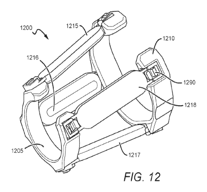
[0086] Figure 12 shows a load carrying device 1200 comprising a distal cuff
1205 and a
proximal cuff 1210 connected by elongated compression members 12. Figure 13
shows a front
view of load carrying device 1200. Load carrying device 1200 is different than
load carrying
device 100 in that elongated compression members 1215, 1216, 1217, and 1218
removably
couple with cuffs 1205 and 1210 via a ratchet engagement.
[0087] Figure 14 and Figure 15 show toothed portions 1280 and 1285 on cuffs
1205 and 1210,
respectively. The toothed portions 1280 and 1285 are sized and dimensioned to
engage toothed
portions on an elongated compression member. Figures 16 and 17 show elongated
compression
member 1215 having a toothed portion 1221 and 1222. Other mechanical
engagements are
contemplated, including a pin/screw and slot, and a double prong and bracket.
One benefit of
these mechanical engagements is they only require a very low profile of space
beyond the skin.
Figure 17 shows the profile of the elongated compression member 1215, with the
main body
being linear along its longitudinal axis and symmetrical about both the
longitudinal and
perpendicular axis. The side of the elongated compression member in contact
with the skin is
rounded along the edges for both comfort and to allow proper compression and
release of soft
tissue.
[0088] Figure 18 shows a side view of the ratchet engagement of load carrying
device 1200 and
Figure 19 shows a top perspective view of the ratchet engagement. The ratchet
engagement
allows elongated compression members to removably couple with cuffs 1205 and
1210. The
ratchet engagement also allows for adjustment and repositioning of the
elongated compression
members relative to the user's bone. This allows for adjustment of the
degree/level of
compression and can be used to fit device 1200 to a user's limb. It also
allows for the angle of
the elongated compression members to be adjusted (by independently adjusting
each end of the
compression member).
17
CA 03043183 2019-05-07
WO 2018/089712 PCT/US2017/060967
[0089] Figure 20 shows a load carrying device 2000 that has a gun holster 2075
attached thereto
for holding a gun. Holster 2075 can couple to an elongated compression member
or a cuff of
device 2000 via any fastener suitable for securing holster 2075 in place. For
example, the
elongated compression member or cuff may have various attachment mechanisms
such as a
picatinny rail, through slot, hook and loop, or angled surface for mounting
any conceivable
device or tool of reasonable size and weight.
[0090] Load carrying device 2000 also has straps to close the support cuff
openings for ease of
donning. The strap consists of a first end, which is fixed to the cuff at one
side of the opening,
and a second end, which is removably coupled with the opposing side of the
opening. This
coupling can comprise any adjustable-length connector for providing tension to
reduce the size
of the opening, including straps with buckles. The strap may also be
adjustable through means
including but not limited to a strap adjuster or tension lock. The strap may
also consist of a small
section of elastic material, to allow for a pre-determined amount of expansion
of the cuff during
flexion or other instances of an increase in cross-sectional area of the limb
at the location where
the cuff resides.
[0091] Figure 21 shows a load distribution system 2100 in a bent configuration
and Figure 22
shows system 2100 in a straight configuration. System 2100 comprises a first
limb load carrying
device 2120 and a second limb carrying device 2140 that work together. It is
contemplated that
first limb carrying device 2120 and second limb carrying device 2140 can be
disposed on either
the upper limb or lower limb. The first and second load carrying devices 2120
and 2140 are
coupled by a rigid and hinging elbow connector 2060. Connector 2060
functionally couples the
first and second load carrying devices 2120 and 2140 to help distribute weight
and provide better
stabilization.
[0092] Figure 23 shows a load carrying device 2300 worn by a user in
combination with an
elbow strap 2330. Strap 2330 goes around the user's elbow to help secure
device 2300 in place
when carrying load 2320. It is contemplated that strap 2330 has a quick
release mechanism.
Strap 2330 can be modified to provide tension and the tension could be
adjustable by the user.
[0093] Figure 24 shows an embodiment of a load carrying device 2400 for a
dynamic strap that
comprises a first end which is attached to the end of a flat spiral spring or
constant force spring
18
CA 03043183 2019-05-07
WO 2018/089712 PCT/US2017/060967
2430 inside a protective case that is attached to or integrated into the
lateral side of the proximal
support cuff. Constant force spring 2430 is wound around a spool 2410. Spool
2410 rotates
freely around the center post of the circular box, so that constant force
spring 2430, which is
fixed to spool 2410, may be unwound and rewound as necessary. The dynamic
strap is drawn
across the cubital fold anterior to the arm, turning back posteriorly above
the epicondyle, and
back anteriorly across the cubital fold to the second end, which is attached
in a static manner to
the medial side of the proximal support cuff. This arrangement allows for the
elbow strap to
maintain set tension around the forearm and epicondyle as the arm is flexed
and extended.
Additionally, it should be noted that the second end may be designed to be
adjusted initially to
the user, through perhaps a prong and hole, or other alternative.
[0094] In an alternative embodiment is a static elbow strap comprising a first
end coupled to a
point on the lateral side of the proximal support cuff. The strap is drawn
across the cubital fold
anterior to the arm, turning back posteriorly above the epicondyle, and back
anteriorly across the
cubital fold to the second end, which is coupled to the medial side of the
proximal support cuff.
These couplings at the first and second end of the static elbow strap may
conceivably be either
measured for a particular user and fixed, or consist of a manual adjustment
method such as a
strap adjuster or tension lock.
[0095] In either of these strap embodiments the second end of the strap could
either be fixed
permanently to the proximal cuff, or preferably, removably, to increase ease
of donning.
[0096] The inventive subject matter includes methods of fitting a load
carrying device to a user.
For example, the cuffs can be positioned at 1.5 inches from the styloid and at
3 inches from the
cubital fold. The distance between the styloid and cubital fold is used to
determine the
approximate length of the compression members. Alternatively, the cuffs can be
attached at a
location that will not interfere with either the motion of the wrist or
flexion of the elbow. It is
contemplated that cuffs can be custom manufactured to a specific size and
shape by measuring,
scanning, or casting the arm.
[0097] The inventive subject matter also includes load carrying devices that
comprise only one
cuff that has an inside surface comprising alternative compression and relief
zones configured to
compress the soft tissue and stabilize the bone. The width of the cuff and the
size of the
19
CA 03043183 2019-05-07
WO 2018/089712 PCT/US2017/060967
compression and relief zones can be selected based on the weight of the
expected loads. For
example, if the load carrying device is used to carry a light load, such as a
mobile electronic
device, then the compression and relief zones may be relatively small. In such
applications, the
load carrying device preferably has a quick release attachment point with a
hinging and/or
rotating joint to adjust the position of the electronic device for better
visibility and usability. In
the warfighter application, the electronic device could be configured to
monitor the weight of
your load.
[0098] In yet other aspects of alternative embodiments, the load carrying
devices described
herein can further include actuators, sensors, and control systems for
automating load
distribution. For example, the load carrying devices can be programmed to self
adjust based on
the user's movements and/or external conditions (e.g., weather, etc.).
[0099] The single cuff embodiments can optionally connect to a second cuff via
an elongated
compression member or a rigid frame structure to increase the load capacity.
[00100] The load distribution systems contemplated herein preferably comprise
modular
components that may be interchangeable for rapid replacement. The system may
be provided as
a kit which includes sets of struts, each provided with mounting locations and
associated fixtures,
adjustable straps or rigid custom designed cuffs that can be connected to the
struts to form distal
and proximal cuffs, attachment points for the ends of the struts, and
additional mountable
fixtures designed to hold selected implements where and as needed for given
application.
Different components comprising a particular LDS may be off-the-shelf or
custom designed via
a priori measurements and/or scanning. The struts, which are made of rigid
material, which can
be a composite such as carbon composites, plastics and other rigid materials
known in the art of
prosthetic sockets, are prefabricated using a variety of techniques including,
but not limited to,
3D printing for maximal cost effectiveness.
[00101] The struts exert the compression zones longitudinally, while allowing
tissue to bulge
outward, thereby creating the osseostabilization system, which captures the
bone but does not
cause discomfort to the user. This alternating compression and release
technology provides a
platform for safe and efficient mounting of loads to various locations on the
operator's
extremities. In various embodiments of the LDS, the specific compression
levels can be
CA 03043183 2019-05-07
WO 2018/089712 PCT/US2017/060967
constant, having been adjusted and customized a priori to the individual, or
they can include
dynamic adjustment means which can be mechanical, electromechanical, chemical,
or any other
suitable means. In the dynamic LDS embodiments, the adjustments may be
performed manually
by the user, or they can be automatic, responding to data input from embedded
sensors that
measure local pressure levels as a function of time.
[00102] The LDS can bring osseostabilization technology to Tactical Assault
Light Operator
Suit TALOS, allowing a more biomechanically efficient man-machine interface,
increasing
system performance and operator efficiency in the field. Improvements in the
human interface
would also enable superior performance from the warrior web, and may even
allow revisiting of
heavier suits such as HULC and XOS 2, as well as other 'smart" enhanced
human/technology
interfaces. By placing the task of connectivity on the neuromusculoskeletal
system as a unified
whole, rather than on simple soft tissue weight bearing, the human operator
and any attached
devices become a biomechanically integrated unit. The inventor believes that
by viewing the
human musculoskeletal system with externally attached devices/payloads as a
unified and
integrated system, it will be possible to eliminate bulky and cumbersome
interface elements.
[00103] As used in the description herein and throughout the claims that
follow, the meaning
of "a," "an," and "the" includes plural reference unless the context clearly
dictates otherwise.
Also, as used in the description herein, the meaning of "in" includes "in" and
"on" unless the
context clearly dictates otherwise.
[00104] Also, as used herein, and unless the context dictates otherwise, the
term "coupled to"
is intended to include both direct coupling (in which two elements that are
coupled to each other
contact each other) and indirect coupling (in which at least one additional
element is located
between the two elements). Therefore, the terms "coupled to" and "coupled
with" are used
synonymously.
[00105] Thus, specific compositions and methods of load distribution systems
have been
disclosed. It should be apparent, however, to those skilled in the art that
many more
modifications besides those already described are possible without departing
from the inventive
concepts herein. The inventive subject matter, therefore, is not to be
restricted except in the
spirit of the disclosure. Moreover, in interpreting the disclosure all terms
should be interpreted
21
CA 03043183 2019-05-07
WO 2018/089712 PCT/US2017/060967
in the broadest possible manner consistent with the context. In particular the
terms "comprises"
and "comprising" should be interpreted as referring to the elements,
components, or steps in a
non-exclusive manner, indicating that the referenced elements, components, or
steps can be
present, or utilized, or combined with other elements, components, or steps
that are not expressly
referenced.
22