Note: Descriptions are shown in the official language in which they were submitted.
CA 03043228 2019-05-07
WO 2018/102435 PCT/US2017/063749
WIRELESS RESONANT CIRCUIT AND VARIABLE INDUCTANCE VASCULAR IMPLANTS
FOR MONITORING PATIENT VASCULATURE AND FLUID STATUS AND SYSTEMS AND
METHODS EMPLOYING SAME
FIELD OF THE DISCLOSURE
[0001] The present invention generally relates to the field of vascular
monitoring. In particular,
the present invention is directed to wireless vascular monitoring implants,
systems, methods, and
software. More specifically, embodiments disclosed herein relate to fluid
volume sensing in the
inferior vena cava (IVC) using wireless, remotely or automatically actuatable
implants for
monitoring or management of blood volume.
BACKGROUND
[0002] Others have attempted to develop vascular monitoring devices and
techniques, including
those directed at monitoring vessel arterial or venous pressure or vessel
lumen dimensions.
However, many such existing systems are catheter based (not wireless) and thus
can only be utilized
in a clinical setting for limited periods of times, and may carry risks
associated with extended
catheterization. For a wireless solution, the complexity of deployment,
fixation and the
interrelationship of those factors with detection and communication have led
to, at best, inconsistent
results with such previously developed devices and techniques.
[0003] Existing wireless systems focus on pressure measurements, which in
the IVC can be less
responsive to patient fluid state than IVC dimension measurements. However,
systems designed to
measure vessel dimensions also have a number of drawbacks with respect to
monitoring in the IVC.
Electrical impedance-based systems require electrodes that are specifically
placed in opposition
across the width of the vessel. Such devices present special difficulties when
attempting to monitor
IVC dimensions due to the fact that the IVC does not expand and contract
symmetrically as do most
other vessels where monitoring may be desired. Precise positioning of such
position-dependent
sensors is a problem that has not yet been adequately addressed. IVC
monitoring presents a further
challenge arising from the physiology of the IVC. The IVC wall is relatively
compliant compared to
other vessels and thus can be more easily distorted by forces applied by
implants to maintain their
position within the vessel. Thus devices that may perform satisfactorily in
other vessels may not
necessarily be capable of precise monitoring in the IVC due to distortions
created by force of the
implant acting on the IVC wall. As such, new developments in this field are
desirable in order to
Page 1 of 84
CA 03043228 2019-05-07
WO 2018/102435 PCT/US2017/063749
provide doctors and patients with reliable and affordable wireless vascular
monitoring
implementation, particularly in the critical area of heart failure monitoring.
SUMMARY OF THE DISCLOSURE
[0004] Embodiments disclosed herein comprise wireless vascular monitoring
devices, circuits,
methodologies, and related techniques for use in assisting healthcare
professionals in predicting,
preventing, and diagnosing various conditions whose indicators may include
vascular fluid status.
Using embodiments disclosed, metrics including, for example, relative fluid
status, fluid
responsiveness, fluid tolerance, or heart rate may be accurately estimated.
[0005] In one implementation, the present disclosure is directed to a
wireless vascular
monitoring implant adapted to be deployed and implanted in a patient
vasculature and positioned at a
monitoring location in a vascular lumen in contact with the lumen wall. The
implant includes a
resilient sensor construct configured to dimensionally expand and contract
with natural movement of
the lumen wall; wherein an electrical property of the resilient sensor
construct changes in a known
relationship to the dimensional expansion and contraction thereof; and the
resilient sensor construct
produces a wireless signal indicative of the electrical property, the signal
being readable wirelessly
outside the vascular lumen to determine a dimension of the vascular lumen; the
resilient sensor
construct is configured and dimensioned to engage and substantially
permanently implant itself on or
in the lumen wall; the resilient sensor construct has a variable inductance
correlated to its
dimensional expansion and contraction along at least one dimension; and the
resilient sensor
construct produces, when energized by an energy source directed at the
construct, a signal readable
wirelessly outside the patient's body indicative of the value of the at least
one dimension, whereby a
dimension of the vascular lumen may be determined; wherein the resilient
sensor construct
comprises a coil configured to engage at least two opposed points on the
vascular lumen wall, the
coil having an inductance that varies based on the distance between the two
opposed points on the
coil corresponding a distance between the points on the lumen wall; wherein
the coil is rotationally
symmetrical about a longitudinal axis; wherein the resilient sensor construct
is configured to expand
and contract with the lumen wall along substantially any transverse axis of
the vessel to change the
variable inductance; wherein the resilient sensor construct, further comprises
a frame having at least
one resilient portion formed with at least two points configured to be
positioned opposite one
another so as to engage opposed surfaces of the vascular lumen wall when the
sensor construct is
positioned at the monitoring location in contact with the lumen wall, wherein
the coil is formed on
Page 2 of 84
CA 03043228 2019-05-07
WO 2018/102435 PCT/US2017/063749
the frame by at least one wire disposed around the frame so as to form plural
adjacent wire strands
around the frame; wherein the resilient sensor construct comprises a resonant
circuit having a
resonant frequency that varies with the variable inductance, the signal being
correlated with the
resonant frequency; wherein the coil comprises a resonant circuit having
inductance and a
capacitance defining a resonant frequency, wherein the resonant frequency
varies based on the
distance between the at least two points; and the coil is configured to be
energized by a magnetic
field directed at the coil from outside the patient's body.
[0006] In another implementation, the present disclosure is directed to a
wireless vascular
sensing system that includes a wireless vascular monitoring implant adapted to
be deployed and
implanted in a patient vasculature and positioned at a monitoring location in
a vascular lumen in
contact with the lumen wall, the implant comprising a resilient sensor
construct configured to
dimensionally expand and contract with natural movement of the lumen wall;
wherein an electrical
property of the resilient sensor construct changes in a known relationship to
the dimensional
expansion and contraction thereof; and the resilient sensor construct produces
a wireless signal
indicative of the electrical property, the signal being readable wirelessly
outside the vascular lumen
to determine a dimension of the vascular lumen; and further comprising means
for excitation of the
resilient sensor construct to produce a frequency response signal indicative
of a dimension of the
lumen at a time correlated to the excitation; an antenna module configured to
at least receive the
frequency signal from the implant, the antenna module further configured to be
disposed outside the
patient's body; and a control system communicating with the antenna module to
at least receive a
representation of the frequency signal from the antenna module and present
data interpreting the
frequency signal to estimate a dimension of the vascular lumen at the
monitoring location.
[0007] In still another implementation, the present disclosure is directed
to a system for
monitoring a patient vascular lumen dimension. The system includes a wireless
vascular sensor
configured to be positioned in a vascular lumen at a monitoring location in
engagement with the
lumen wall, the sensor including a resonant circuit with a resonant frequency
that varies correlated
to expansion and contraction of the sensor with natural movement of the lumen
wall in response to
changes in patient fluid volume; means for exciting the resonant circuit of
the sensor to produce a
frequency signal indicative of a dimension of the lumen at a time correlated
to the exciting; an
antenna module configured to at least receive the frequency signal from the
implant, the antenna
module further configured to be disposed outside the patient's body; and a
control system
Page 3 of 84
CA 03043228 2019-05-07
WO 2018/102435
PCT/US2017/063749
communicating with the antenna module to at least receive a representation of
the frequency signal
from the antenna module and present data interpreting the frequency signal to
estimate the patient
fluid status based on a sensed vascular lumen dimension; comprising a wearable
antenna comprising
a belt configured to be wrapped around a patient's waist or torso to form a
first coil around a first
axis; and a wireless sensor comprising a second coil formed around a second
axis, the wireless
vascular sensor being configured to be implanted in a vessel such that the
second axis is generally
parallel to the first axis; wherein a current in the first coil produces a
first electromagnetic field, the
first electromagnetic field passing through the second coil along the second
axis, thereby producing
a current in the second coil resulting in a signal receivable by the first
coil of the wearable antenna;
further comprising a control system configured to generate the current in the
first coil and receive the
signal from the first coil, the control system including a switch for
switching between a transmit
mode wherein a current is sent to the first coil and a receive mode wherein a
signal is received by the
first coil; wherein the second coil comprises a resonant circuit with a
resonant frequency that varies
in correlation to a physiological parameter to be measured and receivable
signal comprises a
frequency signal produced by the resonant circuit; wherein the wireless sensor
is a vascular sensor
comprising a resilient sensor construct configured to be positioned within a
vascular lumen and
substantially permanently implant itself on or in the lumen wall, the sensor
construct including a coil
configured to expand and contract with the lumen wall along substantially any
transverse axis of the
vascular lumen to change the variable resonant frequency and wherein the coil
is rotationally
symmetrical about a longitudinal axis so as to be operable at any rotational
position within the
vascular lumen.
[0008] In
still another implementation, the present disclosure is directed to a method
for
wireles sly monitoring changes in a dimension of a body lumen of a patient.
The method includes
wirelessly receiving outside the patient's body a variable inductance-based
signal from an implant
substantially permanently implanted on or in the body lumen wall wherein the
variable inductance-
based signal varies based on changes in geometry of the lumen wall; further
comprising energizing
the implant to produce the variable inductance-based signal in response to the
energizing; wherein
the body lumen comprises a patient vascular lumen and the method further
comprises delivering the
implant to a monitoring location within the vascular lumen; wherein the
delivering comprises:
placing the implant within a sheath of a delivery catheter; intravascularly
positioning a distal end of
the delivery catheter at the monitoring location; and deploying the implant
from the delivery
Page 4 of 84
CA 03043228 2019-05-07
WO 2018/102435 PCT/US2017/063749
catheter with a deployment member slideably disposed in the sheath; wherein:
the implant comprises
a resiliently expandable and collapsible sensor construct; the placing
comprises collapsing the sensor
construct to be placed within the sheath; and the deploying comprises forcing
the sensor construct
out of the distal end of the sheath such that a leading end of the sensor
construct expands to contact
the vascular lumen wall before a trailing end of the sensor construct leaves
the delivery catheter.
[0009] In yet another implementation, the present disclosure is directed to
a method for
wireles sly monitoring changes in a dimension of a body lumen of a patient.
The method includes
wirelessly receiving outside the patient's body a variable inductance-based
signal from an implant
substantially permanently implanted on or in the body lumen wall wherein the
variable inductance-
based signal varies based on changes in geometry of the lumen wall; wherein
the variable
inductance-based signal varies based on changes in geometry of the wall of a
vascular lumen within
which the implant is implanted and the method further comprises: processing
the signal to determine
variations in vascular lumen area over time, wherein the variations in
vascular lumen area are
correlateable to patient fluid status; and interpreting the determined
variations in lumen area over
time to asses patient fluid status.
[0010] In a further implementation, the present disclosure is directed to a
diagnostic method for
determining patient fluid status. The method includes wirelessly receiving
outside the patient's body
a variable inductance-based signal from an implant substantially permanently
implanted on or in a
wall of a vascular lumen wherein the variable inductance-based signal varies
based on changes in
geometry of the lumen wall; processing the signal to determine variations in
vascular lumen area
over time, wherein the variations in vascular lumen area are correlateable to
patient fluid status; and
interpreting the determined variations in lumen area over time to asses
patient fluid status.
[0011] These and other aspects and features of non-limiting embodiments of
the present
disclosure will become apparent to those skilled in the art upon review of the
following description
of specific non-limiting embodiments of the invention in conjunction with the
accompanying
drawings.
BRIEF DESCRIPTION OF THE DRAWINGS
[0012] For the purpose of illustrating the disclosure, the drawings show
aspects of one or more
embodiments of the disclosure. However, it should be understood that the
present disclosure is not
limited to the precise arrangements and instrumentalities shown in the
drawings, wherein:
Page 5 of 84
CA 03043228 2019-05-07
WO 2018/102435 PCT/US2017/063749
FIG. 1 schematically depicts an embodiment of a wireless resonant circuit-
based vascular
monitoring ("RC-WVM") system of the present disclosure;
FIG. lA schematically depicts a portion of an alternative embodiment of a RC-
WVM system of the
present disclosure;
FIGS. 2 and 2A illustrate alternative embodiments of RC-WVM implants made in
accordance with
the teachings of the present disclosure;
FIG. 2B is a schematic, detailed view of the capacitor section of the RC-WVM
implant illustrated in
FIG. 2;
FIGS. 3, 3A, 3B, 3C and 3D illustrate an embodiment of a belt antenna as
depicted schematically in
the system of FIG. 1;
FIG. 3E schematically depicts the orientation of the antenna belt and magnetic
field generated
thereby with respect to an implanted RC-WVM implant;
FIG. 4 is a block diagram illustrating an embodiment of system electronics;
FIGS. 5A and 5B illustrate fixed frequency RF burst excitation signal wave
forms;
FIGS. 6A and 6B illustrate sweep frequency RF burst excitation signal wave
forms;
FIG. 7 is a block diagram depicting a multi-channel, direct digital
synthesizer used in signal
generation modules of control systems in embodiments disclosed herein;
FIGS. 7A and 7B illustrate multi-frequency RF burst excitation signal wave
forms;
FIG. 8 illustrates waveform pulse shaping;
FIGS. 9A, 9B and 9C schematically illustrate aspects of an embodiment of a
delivery system for RC-
WVM implants as disclosed herein, wherein FIG. 9A shows an overall view of the
delivery
system and its sub-components, FIG. 9B shows a detail of the distal end with
the RC-WVM
loaded, and FIG. 9C depicts a partial deployment of an RC-WVM implant from the
delivery
sheath into the IVC;
FIGS. 10A, 10B, 10C, 10D and 10E illustrate signals obtained in pre-clinical
experiments using a
prototype system and an RC-WVM implant as shown in FIGS. 1 and 2;
Page 6 of 84
CA 03043228 2019-05-07
WO 2018/102435 PCT/US2017/063749
FIGS. 11A and 11B schematically depict components and possible arrangements of
alternative
clinical or home systems employing RC-WVM implants and control systems as
disclosed
herein;
FIGS. 12A, 12B, 12C, 13A, 13B, 13C, 13D, 14A, 14B, 15A, 15B, 16A, 16B, 17A,
17B, 18, 19A,
and 19B illustrate alternative embodiments of RC-WVM implants according to the
present
disclosure;
FIGS. 20A and 20B illustrate alternative frame structures for use in an RC-WVM
implant as
disclosed herein;
FIGS. 21A and 21B illustrate an example of a method of making an RC-WVM
implant embodiment
according to the present disclosure;
FIG. 22A illustrates an alternative system in accordance with the present
disclosure for energizing
and communicating with RC-WVM implants, including a planar antenna module with
send
and receive coils;
FIG. 22B schematically depicts a further alternative antenna module;
FIGS. 23A and 23B illustrate signals obtained in pre-clinical experiments
using the prototype
implant shown in FIG. 12A and antenna module configuration shown in FIG. 22B;
FIG. 24A is a circuit diagram of an example excitation and feedback monitoring
("EFM") circuit
that can be used with embodiments of RC-WVM implants and systems as described
herein;
FIG. 24B is a circuit diagram of another example EFM circuit that can be used
with embodiments of
RC-WVM implants and systems as described herein;
FIG. 25A is a circuit diagram of an antenna module tuning and detuning network
that can be used
with an EFM circuit like that of FIGS. 24A or 24B;
FIG. 25B schematically depicts a further embodiment of antenna module coils
arranged to provide
geometric decoupling of the transmit and receive signals;
FIG. 26A illustrates an alternative signal generation module for systems
according to embodiments
disclosed herein;
FIG. 26B illustrates an alternative receiver chain signal conditioning module
for use in systems
according to embodiments disclosed herein;
Page 7 of 84
CA 03043228 2019-05-07
WO 2018/102435 PCT/US2017/063749
FIG. 26C illustrates an alternative data conversion module for use in systems
according to
embodiments disclosed herein;
FIGS. 27A and 27B illustrate alternative belt antenna embodiments utilizing
variable length of coil
features;
FIGS. 28A and 28B illustrate alternative active and passive diode switches for
use in antenna
element embodiments disclosed herein;
FIGS. 29A and 29B illustrate alternative antenna belt embodiments;
FIGS. 30A and 30B are block diagrams illustrating alternative control systems
with an on-board,
implanted, power supply;
FIGS. 31A and 31B are perspective views of alternative embodiments of wireless
implants with an
on-board power supply and control electronics according to further embodiments
disclosed
herein;
FIG. 32 is a schematic depiction of a wireless implant including on-board
power and electronics
communicating with an implanted cardiac monitoring device; and
FIG. 33 is a block diagram depicting one possible embodiment of a computer-
based implementation
of aspects of an exemplary control system in the form of a specialized
computing device or
system.
DETAILED DESCRIPTION
[0013] Aspects of the present disclosure are directed to wireless, resonant
circuit-based vascular
monitoring ("RC-WVM") implants, systems, methods, and software, including
excitation and
feedback monitoring ("EFM") circuits that can be used to energize an RC-WVM
implant with an
excitation signal and receive characteristic feedback signals produced by the
RC-WVM implant. By
automatically or manually analyzing the feedback produced by the RC-WVM
implant, it is possible
to assist healthcare professionals in predicting, preventing, and diagnosing
various heart-related,
kidney-related, or vascular-related health conditions. For example, the
feedback produced by the
RC-WVM implant at a particular time can be compared to feedback produced by
the RC-WVM
implant at other times and/or feedback produced by a baseline RC-WVM implant
in order to
understand vessel geometry and therefore estimate relative fluid status, fluid
responsiveness, fluid
tolerance, heart rate, respiration rate and/or other metrics. One or more of
these estimations can be
Page 8 of 84
CA 03043228 2019-05-07
WO 2018/102435 PCT/US2017/063749
generated automatically or manually in order to monitor the status of a
patient and provide feedback
to a healthcare professional and/or the patient in case of any anomalies or
relevant trends.
System Overview
[0014] The unique physiology of the IVC presents some distinctive
challenges in attempting to
detect and interpret changes in its dimensions arising from changes in patient
fluid state. For
example, the IVC wall in a typical monitoring region (i.e., between the
hepatic and renal veins) is
relatively compliant compared to other vessels, which means that changes in
vessel volume can
result in different relative distance changes between the anterior-posterior
walls as compared to the
lateral-medial walls. Thus, it is quite typical that changes in fluid volume
will lead to paradoxical
changes in the geometry and motion of the vessel; that is, as the blood volume
reduces the IVC tends
to get smaller and collapse with respiration, and as the blood volume
increases the IVC tends to get
larger and the collapse with respiration is reduced. Systems and implants
disclosed herein are
uniquely configured to compensate for and interpret such paradoxical changes.
[0015] As shown in FIG. 1, systems 10 according to the present disclosure
may generally
comprise RC-WVM implant 12 configured for placement in a patient's IVC,
control system 14,
antenna module 16 and one or more remote systems 18 such as processing
systems, user
interface/displays, data storage, etc., communicating with the control and
communications modules
through one or more data links 26, which may be wired or remote/wireless data
links. In many
implementations, remote system 18 may comprise a computing device and user
interface, such as a
laptop, tablet or smart phone, which serves as an external interface device.
[0016] RC-WVM implants 12 generally comprise a variable inductance,
constant capacitance,
resonant L-C circuit formed as a resiliently collapsible coil structure,
which, when positioned at a
monitoring position within the patient's IVC, moves with the IVC wall as it
expands and contracts
due to changes in fluid volume. The variable inductance is provided by the
coil structure of the
implant such that the inductance changes when the dimensions of the coil
change with the IVC wall
movement. The capacitive element of the circuit may be provided by a discrete
capacitor or
specifically designed inherent capacitance of the implant structure itself.
Embodiments of RC-
WVM implant 12 also may be provided with anchoring and isolation means
inherently designed into
the implant structure, or with distinct additional such structures, to ensure
that the implant is securely
and properly positioned in the IVC without unduly distorting the vessel wall
so as to distort or
Page 9 of 84
CA 03043228 2019-05-07
WO 2018/102435 PCT/US2017/063749
otherwise negatively impact measurements determined by the implant. In
general, RC-WVM
implants 12 are configured to at least substantially permanently implant
themselves in the vascular
lumen wall where placed upon deployment and do not require a physical
connection (for
communications, power or otherwise) to devices outside the patient's body
after implantation.
"Substantially permanently implanted" as used herein means that in normal
usage the implant will,
throughout its useful, operational life, remain implanted in the vascular
lumen wall and may to
varying degrees become integrated into the vascular lumen wall by tissue
ingrowth, but the implant
may be intentionally removed as medically dictated by an intravascular
interventional or surgical
removal procedure specifically undertaken for the purpose of removing the
implant. Details of
alternative embodiments of implant 12, shown in FIGS. 2, 2A, 12A, 12B, 12C
13A, 13B, 13C, 13D,
14A, 14B, 15A, 15B, 16A, 16B, 17A, 17B, 18, 19A, and 19B, are provided below.
In particular, it
should be noted that any of alternative RC-WVM implants 12, specifically any
of implant
embodiments 12a- k, m, n and p, may be utilized in alternative systems 10 as
described herein
without further modification of the systems except as may be identified.
[0017] Control system 14 comprises, for example, functional modules for
signal generation,
signal processing and power supply (generally comprising the EFM circuits and
indicated as module
20) and communications module 22 to facilitate communication and data transfer
to various remote
systems 18 through data links 26 and optionally other local or cloud-based
networks 28. Details of
alternative embodiments of control system 14, modules 20 and 22, and elements
of alternative EFM
circuits are described below and illustrated in FIGS. 4, 7, 24A, 24B, 25A,
25B, 26A, 26B and 26C.
After analyzing signals received from RC-WVM implant 12 after being excited by
a transmit coil of
an EFM circuit, results may be communicated manually or automatically through
remote system 18
to the patient, a caregiver, a medical professional, a health insurance
company, and/or any other
desired and authorized parties in any suitable fashion (e.g., verbally, by
printing out a report, by
sending a text message or e-mail, or otherwise).
[0018] Antenna module 16 is connected to control system 14 by power and
communication
link 24, which may be a wired or wireless connection. Antenna module 16
creates an appropriately
shaped and oriented magnetic field around RC-WVM implant 12 based on signals
provided by the
EFM circuitry of control system 14. The magnetic field energizes the L-C
circuit of RC-WVM
implant 12 causing it to produce a "ring-back" signal indicative of its
inductance value at that
moment. Because the inductance value is dependent on the geometry of the
implant, which changes
Page 10 of 84
CA 03043228 2019-05-07
WO 2018/102435 PCT/US2017/063749
as mentioned above based on dimensional changes of the IVC in response to
fluid state heart rate
etc., the ring-back signal can be interpreted by control system 14 to provide
information as to the
IVC geometry and therefore fluid state. Antenna module 16 thus also provides a
receive
function/antenna as well as a transmit function/antenna. In some embodiments
the transmit and
receive functionality are performed by a single antenna, in others each
function is performed by a
separate antenna. Antenna module 16 is schematically depicted in FIG. 1 as an
antenna belt, which
embodiment is described in more detail below and shown in FIGS. 3A-D.
[0019] FIG. lA illustrates one alternative embodiment of antenna module 16
as antenna
pad 16a, in which transmit coil 32 and receive coil 34 are disposed in a pad
or mattress 36 on which
the patient lays on his/her back with RC-WVM implant 12 (implanted in the IVC)
positioned over
coils 32, 34. Antenna module 16 as shown in FIG. lA is functionally equivalent
to other alternative
antenna modules disclosed herein; it is connected to control system 14 by
power and
communications link 24 as described above. Further alternative embodiments and
components of
antenna module 16 are also shown in FIGS. 22A, 22B, 27A, 27B, 28A, 28B, 29A
and 29B and
described in more detail below. Planar-type antenna modules also may be
configured in wearable
configurations, e.g., wherein the antenna coil is integrated into a wearable
garment such as a
backpack or vest. Antenna module 16 may also comprise a coil adapted to be
fastened directly to
the patient's skin by tape, glue or other means, e.g. over the abdomen or
back, or integrated into
furniture such as a chair back. As will be appreciated by persons skilled in
the art, the various
embodiments of antenna module 16 as described herein may be employed with
system 10 as shown
in FIG. 1 without further changes to the system or antenna module other than
as specifically
identified herein.
[0020] The variable inductance L-C circuit produces a resonant frequency
that varies as the
inductance is varied. With the implant securely fixed at a known monitoring
position in the IVC,
changes in geometry or dimension of the IVC cause a change in configuration of
the variable
inductor, which in turn cause changes in the resonant frequency of the
circuit. These changes in the
resonant frequency can be correlated to changes in the vessel geometry or
dimension by the RC-
WVM control and communication system. Thus, not only should the implant be
securely positioned
at a monitoring position, but also, at least a variable coil/inductor portion
of the implant should have
a predetermined resilience and geometry. Thus, in general, the variable
inductor is specifically
configured to change shape and inductance in proportion to a change in the
vessel geometry. In
Page 11 of 84
CA 03043228 2019-05-07
WO 2018/102435 PCT/US2017/063749
some embodiments, an anchoring and isolation means will comprise appropriately
selected and
configured shape and compliance in the sensor coil structure of the implant so
as to move with the
vessel wall while maintaining position. Such embodiments may or may not
include additional
anchoring features as discussed in more detail below. Alternatively, an
anchoring and isolation
means may comprise a separate structure spaced and/or mechanically isolated
from a variable
inductor coil structure such that the anchoring function is physically and/or
functionally separated
from the measuring/monitoring function such that any distortion or constraint
on the vessel caused
by the anchor is sufficiently distant and/or isolated from the variable
inductor so as not to unduly
affect measurements.
[0021] RC-WVM implant 12 as a variable inductor is configured to be
remotely energized by
an electric field delivered by one or more transmit coils within the antenna
module positioned
external to the patient. When energized, the L-C circuit produces a resonant
frequency which is then
detected by one or more receive coils of the antenna module. Because the
resonant frequency is
dependent upon the inductance of the variable inductor, changes in geometry or
dimension of the
inductor caused by changes in geometry or dimension of the vessel wall cause
changes in the
resonant frequency. The detected resonant frequency is then analyzed by the RC-
WVM control and
communication system to determine the change in the vessel geometry or
dimension. Information
derived from the detected resonant frequency is processed by various signal
processing techniques as
described herein and may be transmitted to various remote devices such as a
healthcare provider
system or patient system to provide status, or in appropriate instances,
alerts or modifications in
treatment. In order to facilitate measurement of the detected resonant
frequency, it may be desirable
to provide designs with a relatively higher Q factor, i.e. resonant circuit
configurations that maintain
signal/energy for relatively longer periods, especially when operating at
lower frequencies. For
example, to realize advantages of designs employing Litz wire as further
described herein, it may be
desirable to operate in a resonant frequency range of below 5 MHz, typically
between about 1MHz
and 3MHz, in which case resonant circuit configuration with a Q factor of at
least about 50 or
greater may be desired.
An Example of a Complete System Embodiment
[0022] Details of one possible embodiment of a complete, exemplary system
10 are discussed
hereinafter with reference to FIGS. 2-8C. Thereafter, details of further
alternative embodiments of
system components are described. However, it is to be understood that the
exemplary system is not
Page 12 of 84
CA 03043228 2019-05-07
WO 2018/102435 PCT/US2017/063749
limited to use of the specific elements or components shown in FIGS. 2-7 and
9A-C and that any
alternative component thereafter described may be substituted without change
in the overall system
except as may be noted. For example, RC-WVM implant 12 or any of alternative
RC-WVM
implants 12c-k, m, n and p may be substituted for implants 12a or 12b as first
described below.
Similarly, control system 14 may be provided as shown in any of FIGS. 4, 24A,
24B, 26A, 26B,
26C, 28A, 28B, 29A and 29B and/or antenna module 16 may be provided, for
example, as a pad or
belt an antenna such as pad antennal6a, with a single switched antenna coil or
separate, decoupled
transmit and receive coils, or belt antennas 16b, 16c, 16d, 16e or 16f.
[0023] FIG. 2 illustrates one example of RC-WVM implant 12 according to the
present
disclosure as may be used in exemplary system 10. The enlarged detail in the
box of FIG. 2
represents a cross-sectional view taken as indicated. (Note that in the cross-
sectional view,
individual ends of the very fine wires may not be distinctly visible due to
their very small size). In
general, RC-WVM implants 12 comprise a resilient sensor construct generally
including an
inductive coil formed around an open center that to allow substantially
unimpeded blood flow there
through, wherein the inductive coil changes inductance with changes in the
construct geometry as a
result of forces applied to it. In this example, implant 12a is formed as a
resilient, concentric zig-zag
or linked "Z-shapes" structure with a series of straight strut sections 38
joined at their ends by
rounded crown sections 40 forming acute angles. The resultant structure may
also be considered to
be sinusoidal in appearance. This structure may be formed by wrapping
conductive wires 42 onto a
frame or core 44. In this alternative, RC-WVM implant 12a has a shape set
0.010" nitinol wire frame
44 around which 300 strands of 0.04 mm diameter gold, individually insulated,
Litz wire 42 are
wrapped in a single loop. With a single loop wrap, the strands of wire 42
appear substantially
parallel to the frame at any given point, as can be seen in the cross-section
view of FIG. 2.
Individual insulation on Litz wires 42 may be formed as a biocompatible
polyurethane coating. Also
in this particular example, discrete capacitor 46 is provided with a
capacitance of approximately
47rIF (nano-Farads); however, the capacitance may be in the range of about 180
pico-Farads to
about 10 micro-Farads, to cover all potential allowable frequency bands (from
about 148.5kHz to
about 37.5MHz) for RC-WVM implants 12. In one alternative, rather than a
relatively large number
of wire strands in a single loop, a relatively few number of strands, e.g. in
the range of about 10-20
strands, or more particularly about 15 strands, may be arranged in a
relatively larger number of
loops, e.g. in the range of about 15-25 loops, or more particularly about 20
loops. In this
Page 13 of 84
CA 03043228 2019-05-07
WO 2018/102435 PCT/US2017/063749
embodiment the discrete capacitor element is replaced with an inherent coil
capacitance that arises
based spaces between the parallel strands of wire.
[0024] With reference also to FIG. 2B, Litz wire 42 is formed around a
shape set nitinol
frame 44. The two ends of Litz wire 42, which may be covered with a layer of
PET heat shrink
tubing 60, are joined together with a capacitor 46 to form a loop circuit.
Capacitor 46 includes
capacitor terminals 52 connected to Litz wires 42 by solder connection 54 to
gold wire contacts 56.
Gold wire contacts 56 are formed by removing (or burning away) the individual
insulation from a
short section at the end of Litz wires 42 and joining those ends to form solid
contacts, which then
may be joined to capacitor terminals 52 by solder connections 54. The
capacitor, capacitor terminals
and gold wire contacts are encapsulated in an appropriate biocompatible
insulating material 58 such
as a reflowed polymer or epoxy. In alternative embodiments, the entire
structure may then be
covered by a layer of PET heat shrink insulation 60. Alternatively, if
determined that a short circuit
through the frame should not be created, a gap may be provided in the frame at
the capacitor or
elsewhere.
[0025] RC-WVM implant 12a is also optionally provided with anchors 48 to
help prevent
migration of the implant after placement in the IVC. Anchors 48 also may be
formed of nitinol laser
cut sections or shape set wire and bonded to each strut section 38. Barbs 50
extend outwardly at the
end of anchors 48 to engage the IVC wall. In one embodiment, anchors 48 are bi-
directional in both
the cranial and caudal directions; in other embodiments the anchors may be in
one direction, a
mixture of both directions or perpendicular to the vessel.
[0026] The overall structure of RC-WVM implants 12 presents a balance of
electrical and
mechanical requirements. For example, an ideal electrical sensor is as close
to a solenoid as possible
with strut lengths as short as possible and ideally zero, whereas mechanical
considerations of
deployment and stability dictate that implant strut lengths be at least as
long as the diameter of the
vessel into which it is to be deployed to avoid deployment in the wrong
orientation and maintain
stability. Dimensions of elements of RC-WVM implant 12a are identified by
letters A-F in FIG. 2,
and examples of typical values for those dimensions, suited for a range of
patient anatomies, are
provided below in Table I. In general, based on the teachings herein, persons
skilled in the art will
recognize that the uncompressed, free-state (overall) diameter of RC-WVM
implants 12 should not
significantly exceed the largest anticipated fully extended IVC diameter for
the patient in which the
Page 14 of 84
CA 03043228 2019-05-07
WO 2018/102435 PCT/US2017/063749
RC-WVM implant is to be used. RC-WVM implant height generally should be
selected to balance
implant stability at the monitoring position with
geometry/flexibility/resilience providing the ability
to fit in the intended region of the IVC without impacting either the hepatic
or renal veins in the
majority of the population, which could compromise sensing data produced by
the implant. Height
and stability considerations will be influenced, among other factors, by
specific RC-WVM implant
design configuration and whether or not distinct anchor features are included.
Thus, as will be
appreciated by persons skilled in the art, primary design considerations for
RC-WVM implants 12
according to the present disclosure are provision of structures forming
variable inductance L-C
circuits with the ability to perform the measuring or monitoring function
described herein, and which
are configured to securely anchor the structures within the IVC without
distortion of the IVC wall by
providing adequate but relatively low radial force against the IVC wall.
Table I
RC-WVM Implant 12a & 12b
Example Dimensions
Dim. Element Approximate Size (in
Name millimeters)
A Height 10-100, typically about 20
B Strut length 10-100, typically about 25
C Strut diam. 0.1-2, typically about 1.5
Anchor Length
F 1-10, typically about 5
(extending)
Anchor Length
E (barb) 0.25-3, typically about 1.8
Three Sizes:
Overall
D 20 mm/25 mm/32 mm
Diameter
+/- 3 mm
[0027] Another alternative structure for RC-WVM implant 12 is illustrated
by RC-WVM
implant 12b as shown in FIG. 2A. Once again, the enlarged detail in the box of
FIG. 2A represents a
cross-sectional view taken as indicated. In this embodiment, implant 12b has
an overall structure
that is similar to that of implant 12a, formed on a frame with straight strut
sections 38 and curved
crown sections 40. In this embodiment, the discrete capacitor for the previous
embodiment is
replaced with distributed capacitance between the bundles of strands of wire.
Multiple (for example,
approximately fifteen) strands of wire 64 are laid parallel to each other and
twisted into a bundle.
This bundle is then wrapped, multiple times, around the entire circumference
of wire frame 66
(which may be, for example, a 0.010" diameter nitinol wire) resulting in
multiple turns of parallel
Page 15 of 84
CA 03043228 2019-05-07
WO 2018/102435 PCT/US2017/063749
bundles of strands. The insulation between the bundles results in a
distributed capacitance that
causes the RC-WVM to resonate as previously. Overall dimensions are similar
and may be
approximated as shown in Table I. An outer, insulation layer or coating 60 may
be applied either as
previously described or using a dipping or spraying process In this case, the
L-C circuit is created
without a discrete capacitor, but instead by tuning the inherent capacitance
of the structure through
selection of materials and length/configuration of the wire strands. In this
case, 20 turns of 15
strands of wire are used along with an outer insulation layer 60 of silicone
to achieve a capacitance
inherent in implant 12b in the range of approximately 40-50 riF.
[0028] Unlike implant 12a, frame 66 of implant 12b is non-continuous so as
to not complete an
electrical loop within the implant as this would negatively impact the
performance. Any overlapping
ends of frame 66 are separated with an insulating material such as heat shrink
tubing, an insulating
epoxy or reflowed polymer. RC-WVM implant 12b (may or) may not include
anchors. Instead, the
implant is configured to have a compliance/resilience to permit it to move
with changes in the IVC
wall geometry or dimension while maintaining its position with minimal
distortion of the natural
movement of the IVC wall. This configuration can be achieved by appropriate
selection of
materials, surface features and dimensions. For example, the strut section
length of the frame must
balance considerations of electrical performance versus stability, wherein
shorter strut section length
may tend to improve electrical performance but longer strut section length may
increase stability.
[0029] In order to energize RC-WVM implant 12 and receive the signal back
from the implant,
antenna module 16 will functionally include a transmit and a receive antenna
(or multiple antennas).
Antenna module 16 thus may be provided with physically distinct transmit and
receive antennas, or,
as in the presently described exemplary system 10, provided by a single
antenna that is switched
between transmit and receive modes. Antenna belt 16b, shown FIGS. 3 and 3A-D,
illustrates an
example of antenna module 16 employing a single, switched antenna.
[0030] In terms of mechanical construction, belt antenna 16b generally
comprises stretchable
web section 72 and buckle 74 with a connection for power and data link 24. In
one embodiment, in
order for size antenna belt to accommodate patients of different girths (e.g.,
a patient girth range of
about 700-1200 cm), a multi-layer construction made up of a combination of
high-stretch and low-
stretch materials may be employed. In such an embodiment, base layer 76 is a
combination of high-
stretch sections 76a and low-stretch section 76b, which are joined such as by
stitching. Outer
Page 16 of 84
CA 03043228 2019-05-07
WO 2018/102435 PCT/US2017/063749
layer 78, with substantially the same profile as base layer 76, may be
comprised entirely of the high-
stretch material, which may be a 3D mesh fabric. Within each section, antenna
core wire 82 is
provided in a serpentine configuration with an overall length sufficient to
accommodate the total
stretch of the section. Core wire 82 should not itself stretch. Thus, the
stretchability of the fabric
layers is paired with the core wire total length to meet the desired girth
accomodation for a particular
belt design. Outer layer 78 is joined along the edges to base layer 76.
Stitching covered by binding
material 80 is one suitable means for joining the two layers. The layers may
be further bonded
together by a heat fusible bonding material placed between the layers. End
portions 81 of web
section 72 are configured for attachment to buckle 74.
[0031] Core wire 82, which forms the antenna element, is disposed between
the layers and
provided with an extendable, serpentine configuration so that it may expand
and contract with the
stretch of the belt. A mid-section 84 of core wire 82, which corresponds to
low-stretch section 76b,
has a greater width. This section, intended to be placed in the middle of the
patient's back with
antenna belt 16b worn approximately at chest level at the bottom of the rib
cage, provides greatest
sensitivity for reading the signal from RC-WVM implant 12. As one possible
example, core wire 82
may be made up of 300 strands of twisted 46 AWG copper wire with a total
length in the range of
approximately 0.5-3 m. For an antenna belt configured to stretch to
accommodate patient girths in
the range of about 700 to 1200 mm, the total length of core wire 82 may be
approximately 2 m.
[0032] Many ways of providing a workable buckle for such an antenna belt
may be derived by
persons of ordinary skill based on the teachings contained herein. Factors to
be considered in
designing such a buckle include physical security, ease of manipulation by
persons with reduced
dexterity and protection from electrical shock by inadvertent contact with the
electrical connectors.
As an example, buckle 74 is comprised of two buckle halves, inner half 74a and
outer half 74b.
Buckle 74 provides not only physical connection for the belt ends, but also
electrical connection for
the antenna circuit formed by core wire 82. With respect to the physical
connection, buckle 74 is
relatively large in size to facilitate manipulation by persons with reduced
dexterity. A magnetic
latch may be employed to assist closure, for example magnetic pads 86a on
inner buckle half 74a
connect to magnetic pads 86b correspondingly disposed on buckle outer half
74b. If desired, the
system can be configured to monitor for completion of the belt circuit and
therefore detect belt
closure. Upon confirmation of belt closure, the system may be configured to
evaluate the signal
strength received from the implant and an assessment made if the received
signal is sufficient for a
Page 17 of 84
CA 03043228 2019-05-07
WO 2018/102435 PCT/US2017/063749
reading to be completed. If the signal is insufficient, an instruction may be
provided to reposition the
belt to a more optimal location on the patient.
[0033] Electrical connection of core wire 82 may be provided by recessed
connector pins
disposed on opposed connector halves 88a and 88b. Connection of power and data
link 24 may be
provided, for example, through a coaxial RF cable with coaxial connectors
(e.g., SMA plugs) on
buckle 74 and control system 14. As just one possible example, a convenient
length for the power
and data link, using a conventional, 50 Ohm coax cable, is about 3 m.
[0034] As mentioned above, use of a single coil antenna as in antenna belt
16b requires
switching the antenna between transmit and receive modes. Such switching is
executed within
control system 14, an example of which is schematically depicted as control
system 14a in FIG. 4.
In this embodiment, control system 14a includes as functional modules 20 a
signal generator module
20a and a receiver-amplifier module 20b. These functional modules, along with
transmit/receive
(T/R) switch 92 provide for the required switching of antenna belt 16b between
the transmit and
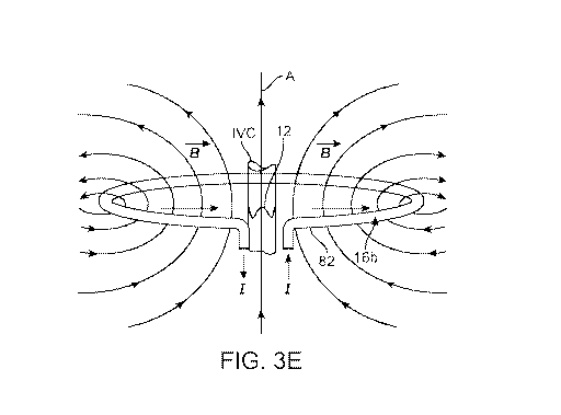
receive modes.
[0035] FIG. 3E schematically illustrates the interaction of the magnetic
field B , created by
antenna belt 16b, with RC-WVM implant 12. Both antenna belt 16b and implant 12
are generally
disposed around an axis (A). For best results with a belt-type antenna, the
axes around which each
are disposed will lie in a substantially parallel orientation and, to the
extent practicable, will lie
coincident as shown in FIG. 3E. When properly oriented with respect to one
another, current (I) in
core wire 82 of antenna belt 16b generates magnetic field B , which excites
the coil of implant 12
to cause it to resonate at its resonant frequency corresponding to its
size/geometry at the time of
excitation. An orientation between the antenna belt 16b and implant 12 as
shown in FIG. 3E
minimizes the power necessary to excite the implant coil and produce a
readable resonant frequency
response signal.
[0036] As with any RF coil antenna system, the antenna and system must be
matched and tuned
for optimum performance. Values for inductance, capacitance and resistance and
their
interrelationship should be carefully considered. For example, the coil
inductance determines the
tuning capacitance while the coil resistance (including the tuning
capacitance) determines the
matching capacitance and inductance. Given the relatively low power of the
disclosed systems,
Page 18 of 84
CA 03043228 2019-05-07
WO 2018/102435 PCT/US2017/063749
special attention is given to these aspects to ensure that an adequately
readable signal is generated by
RC-WVM implant 12 upon actuation by the driving magnetic field. With an
adjustable girth belt
such as antenna belt 16b (or with different size antenna belts), additional
considerations are
presented because of the variable or different lengths of antenna coil
controlled by the control
system. To address these considerations, separate tuning-matching circuits 94,
96, as are understood
in the art, are provided in signal generator module 20a and receiver-amplifier
module 20b,
respectively.
[0037] Using conventional coax cable for RF-power transmission, as is
described above in one
embodiment of power and data link 24, optimal RF power transfer between the
antenna and the
control system is achieved when the system and antenna impedances are matched
to 50 Ohm real
resistance. However, in the embodiment described above, resistance of antenna
belt 16b is generally
far below 50 Ohm. Transformation circuits, as part of tuning-matching
circuits, 94, 96 can be used
to transform the antenna resistance to 50 Ohm. In the case of antenna belt 16b
it has been found a
parallel capacitor transformation circuit is efficient for this purpose.
[0038] In one example of tuning using the system components heretofore
described, a series
capacitor was used, which, in conjunction with a matching capacitor, forms the
total resonance.
Using measured values as set forth below in Table II, a target resonance
frequency was computed at
2.6 MHz based on the inductance and capacitance. Considering the inductance
variation with
stretching of antenna belt 16b at 2.6 MHz, the resonance frequency was
measured to vary only from
about 2.5 MHz to about 2.6 MHz for change in length between 1200mm and 700mm
circumferences
of antenna belt 16b, respectively. Considering the resistance of 11.1 Ohm, the
Q-factor of the
cable/belt assembly computes to be 3. Such a low Q-factor translates to a full
width of the pulse at
half maximum of 600kHz. This is far less than the variation of the resonance
frequency due to
stretching of the belt from 700mm to 1200mm circumference. Tuning values for
antenna belt 16b
were thus determined at 2.6MHz with C.tch=2.2nF and C tune=2.2nF.
Table II
Example of measured values for antenna belt 16b
Belt stretched to 28 cm dia. around water bottle
Resistance Inductance
Point of measurement
[Ohm] [10-6H]
Page 19 of 84
CA 03043228 2019-05-07
WO 2018/102435 PCT/US2017/063749
Measured at buckle
terminals with no cable 0.3 1.69
connected
Measured at output of
T/R switch 92 with 3m 11.1 3.03
coax cable connected
[0039] While it could be expected that a variable length antenna, such as
included in antenna
belt 16b might present difficulties in tuning and maintaining the antenna
tuning as the length
changed, it was discovered that with the present configuration this was not
the case. As described
above, by intentionally employing a cable for power and data link 24 that has
a relatively large
inductance compared to the antenna inductance, the proportional change in the
inductance due to
changes in belt diameter are small enough not to degrade performance.
[0040] Referring again to FIG. 4, in addition to tuning-matching circuit
94, signal generator
module 20a includes components that produce the signal needed for excitation
of RC-WVM
implant 12. These components include direct digital synthesizer (DDS) 98, anti-
aliasing filter 100,
preamplifier 102 and output amplifier 104. In one embodiment, the signal
generator module 20a is
configured to produce an RF burst excitation signal with a single, non-varying
frequency tailored to
a specific RC-WVM implant that is paired with the system (exemplary waveforms
illustrated in
FIGS. 5A and 5B). The RF burst comprises a predefined number of pulses of a
sinusoidal waveform
at the selected frequency with a set interval between bursts. The RF burst
frequency value selected
corresponds to the natural frequency of the paired RC-WVM implant 12 that
would produce a lowest
amplitude in the implant reader output. By doing this, optimum excitation is
achieved for the worst
case of implant response signal.
[0041] In an alternative implementation, control system 14 excites antenna
module 16 at a pre-
determined frequency that is within an expected bandwidth of the paired RC-WVM
implant 12. The
system then detects the response from the paired RC-WVM implant and determines
the implant
natural frequency. Control system 14 then adjusts the excitation frequency to
match the natural
frequency of the paired implant and continues to excite at this frequency for
a complete reading
cycle. As will be appreciated by persons of ordinary skill, frequency
determination and adjustment
as described for this embodiment may be implemented via software using digital
signal processing
and analysis.
Page 20 of 84
CA 03043228 2019-05-07
WO 2018/102435 PCT/US2017/063749
[0042] In another alternative implementation, each individual RF burst
comprises a continuous
frequency sweep over a predefined range of frequencies equal to the potential
bandwidth of the
implant (FIG 6A). This creates a broadband pulse that can energize the implant
at all possible natural
frequencies (FIG 6B). The excitation signal can continue in this "within burst
frequency sweep
mode" or the control system can determine the natural frequency of the sensor
and adjust to transmit
solely at the natural frequency.
[0043] In a further alternative implementation, the excitation comprises a
transitory frequency
sweep over a set of discrete frequency values covering the potential bandwidth
of the paired RC-
WVM implant 12. The frequency is sequentially incremented for each RF burst
and the RMS value
of the RC-WVM implant response is evaluated after each increment. Control
system 14 then
establishes the frequency that produces the maximum amplitude in RC-WVM
implant response and
continues exciting the paired RC-WVM implant at that frequency until a drop of
a predefined
magnitude is detected and the frequency sweep is re-started.
[0044] In yet another implementation, the excitation signal is composed of
a pre-defined set of
frequencies, wherein each remain constant. Control system 14 excites antenna
module 16 (and
hence the paired implant) by applying equal amplitude at all frequency
components. The system
detects the response from the paired implant and determines its natural
frequency. Control system 14
then adjusts the relative amplitude of the excitation frequency set to
maximize the amplitude of the
excitation frequency that is closest to the natural frequency of the paired
implant. The amplitude of
the other frequencies are optimized to maximize the response of the paired
implant while meeting
the requirements of electro-magnetic emissions and transmission bandwidth
limitations.
[0045] In another implementation, direct digital synthesizer (DDS) 98,
diagrammed in FIG. 7,
may be provided as a multi-channel DDS system to generate a simultaneous pre-
defined number of
discrete frequencies belonging to the estimated operational bandwidth of the
paired RC-WVM
implant 12 as shown in FIGS. 7A and 7B. The magnitude of each frequency
component thus may be
independently controlled to provide the optimum excitation to a specific RC-
WVM implant 12 based
on its individual coil characteristics. Additionally, the relative amplitude
of each frequency
component can be independently controlled to provide optimum excitation to the
implant, i.e., the
amplitude of the frequency component is selected in such a way that in the
worst case for the paired
implant to transmit a response signal (i.e., most compressed) the excitation
signal is maximized. In
Page 21 of 84
CA 03043228 2019-05-07
WO 2018/102435 PCT/US2017/063749
this arrangement all outputs from the multi-channel DDS system 98 are summed
together using
summing amplifier 120 based on a high speed operational amplifier as shown in
FIG. 7.
[0046] In yet another implementation, signal generator module 20a can be
configured to provide
pulse shaping as illustrated in FIG. 8. Arbitrary waveform generation based on
direct digital
synthesis 98 is employed to create a pulse of a predefined shape, the spectrum
of which is optimized
in order to maximize the response of the paired RC-WVM implant 12. The
magnitude of the
frequency components that result in decreased ring back signal amplitude is
maximized while the
magnitude of the frequency components that result in increased ring back
signal amplitude is
reduced, in order to obtain an approximately constant output signal amplitude
and thus improved
response from RC-WVM implant 12.
[0047] Referring again to FIG. 4, receiver-module 20b, in addition to
tuning-matching
circuit 96, includes components, e.g., single end input to differential output
circuit (SE to DIFF) 106,
variable gain amplifier (VGA) 108, filter amplifier 110 and output filters
112, for implant response
detection, data conversion and acquisition for signal analysis. During the
receive period, the T/R
switch 92 connects the antenna belt 16b to the receiver-amplifier 20b, via the
tuning and matching
network 96. The response signal induced by the implant 12 in the antenna belt
16b is applied to a
unity-gain single ended to differential amplifier 106. Converting from single-
ended to differential
mode contributes to eliminate common mode noise from the implant response
signal. Since the
amplitude of the implant response signal is in the microvolts range, the
signal is fed, following
conversion from single-ended to differential, into a variable gain
differential amplifier 108 that is
able to provide up to 80 dB (10000 times) voltage gain. The amplified signal
is then applied to a
active band-pass filter-amplifier 110 to eliminate out-of-band frequency
components and provide an
additional level of amplification. The resulting signal is applied to passive,
high-order low pass
filters 112 for further elimination of out-of-band high frequency components.
The output of the
filter is fed into the data conversion and communications module 22. The data
conversion and
communications module 22 includes components to provide data acquisition and
transfer from the
electronic system to the external processing unit. A high-speed analog-to-
digital converter
(ADC) 114 converts the output signal of the receiver module 20b into a digital
signal of a predefined
number of bits (e.g., 12 bits). This digital signal is transferred in parallel
mode to
microcontroller 116. In one implementation, a level shifter circuit is used to
match the logic levels of
the ADC to the microcontroller. The data outputted by the ADC is sequentially
stored in internal
Page 22 of 84
CA 03043228 2019-05-07
WO 2018/102435 PCT/US2017/063749
flash memory of the microcontroller. To maximize the data throughput, direct
memory access
(DMA) is used in this process. Microcontroller 116 is synced with the direct
digital synthesizer 98,
so data acquisition starts when an RF burst is transmitted for excitation of
implant 12. Once
triggered, the microcontroller captures a predefined number of samples (e.g.
1024). The number of
samples multiplied by the sampling period defines the observation window over
which the response
signal from implant 12 is assessed. This observation window is matched to the
length of the response
signal from implant 12, which depends on the time constant of the signal
decay.
[0048] As a means of noise reduction, the response signal of the implant 12
is observed a
predefined number of times (e.g., 256), and the average response is then
computed. This approach
greatly contributes to increasing the signal-to-noise ratio of the detected
signal.
[0049] The average response is then transmitted to an external interface
device 18 (e.g., laptop
computer) by means of communications module 118. Different approaches can be
taken for this. In
one embodiment, the communication is performed using the UART interface from
the
microcontroller and external hardware is employed to convert from UART to USB.
In a second
embodiment, a microcontroller with USB driving capabilities is employed, and
in this case
connection with the external interface device is achieved by simply using a
USB cable. In yet
another implementation, the communication between the microcontroller and the
external interface
device is wireless (e.g. via Bluetooth).
[0050] The system is to be powered by a low voltage power supply unit
(PSU), consisting of a
AC-DC converter with insulation between mains input and output providing a
minimum of 2 Means
of Patient Protection (MOPP) as per Clause 8 of IEC 60601-1:2005+AMD1:2012. In
this way, the
power supply provides protection from electrocution to the user. The PSU is
able to accommodate a
wide range of mains voltages (e.g., from 90 to 264VAC) and mains frequencies
(e.g., 47 to 63 Hz) to
allow operation of the system in different countries with different mains
specifications.
[0051] Control system 14a as described above utilizes a software-based
frequency detection.
Thus, in terms of signal transmission, once the excitation frequency is
optimized, system 10
employing control system 14a with signal generator module 20a operates in open
loop mode, i.e.,
frequency or frequencies and amplitude of the transmit signal are not affected
by RC-WVM
implant 12 response. On the receive side, using amplifier-receiver module 20b,
control system 14a
detects the response signal from RC-WVM implant 12 and such signal is
digitized using a high-
Page 23 of 84
CA 03043228 2019-05-07
WO 2018/102435 PCT/US2017/063749
speed data converter. The raw digitized data is subsequently transferred to a
processing unit (e.g.,
laptop computer or other equipment microcontroller) and digital signal
analysis techniques (e.g. Fast
Fourier Transform) are applied to establish the frequency content of the
signal. Thus, one advantage
of using these software-based techniques is that phased-lock loop (PLL)
circuits or similar circuits
are not used or required in control system 14a.
[0052] A further component of the overall RC-WVM system as described herein
is the RC-
WVM implant delivery system. FIGS. 9A-C illustrate aspects of an intravascular
delivery system
for placing RC-WVM implants 12 at a desired monitoring location within the
IVC, which may
generally comprise delivery catheter 122 including outer sheath 124 and pusher
126 configured to be
received in the lumen of outer sheath 124. In general, insertion of devices
into the circulatory
system of a human or other animal is well known in the art and so is not
described in detail herein.
Those of ordinary skill in the art will understand after reading this
disclosure in its entirety that RC-
WVM implants 12 can be delivered to a desired location in the circulatory
system using, e.g., a
loading tool to load a sterile RC-WVM implant into a sterile delivery system,
which may be used to
deliver an RC-WVM implant to the IVC via a femoral vein or other peripheral
vascular access point,
although other methods may be used. Typically RC-WVM implant 12 will be
implanted using a
delivery catheter, delivery catheter 122 being an illustrative example
thereof, and the RC-WVM
implant will be optimized for delivery through as small a catheter as
possible. To facilitate this,
bends at the implant crowns (or ears as later described, collectively "sensor
construct end portions")
may be small-radius bends to facilitate a low profile when packed into the
delivery catheter as
shown, for example in FIG. 9B. In one alternative, pusher 126 may be provided
with a stepped
distal end 128 having a reduced diameter end portion 130 configured to engage
the inner perimeter
of RC-WVM implant 12 when compressed for delivery. For implant embodiments
employing
anchors (e.g., anchors 48 in FIG. 2), end portion 130 may be configured to
engage an inner perimeter
defined by the anchors in the compressed configuration as illustrated in FIG.
9B. Alternatively,
pusher distal end 128 may be provided with a straight, flat end or other end
shape configured to
cooperate with a specific RC-WVM implant and anchor design.
[0053] In one deployment option, a RC-WVM implant may be inserted from a
peripheral vein
such as the femoral or iliac vein into the IVC to be positioned at a
monitoring location between the
hepatic and renal veins. It will be understood that the implant also may be
introduced from other
venous locations. Depending on implant configuration, when placed in the IVC
for fluid status
Page 24 of 84
CA 03043228 2019-05-07
WO 2018/102435 PCT/US2017/063749
monitoring, specific orientation of RC-WVM implant 12 may be required to
optimize
communication with the belt reader antenna coil. To facilitate desired
placement or positioning, the
length and diameter of RC-WVM implant 12 may be designed so that it gradually
expands as it is
held in position with the pusher 126 and the sheath 124 is withdrawn, as
schematically illustrated in
FIG. 9C. Here, RC-WVM implant 12 is shown partially deployed with the distal
crowns already
engaging the IVC wall while the proximal crowns are still contained within
sheath 124. Such a
gradual, partial deployment helps ensure that RC-WVM implant 12 is properly
positioned in the
IVC. The sensor length to vessel diameter ratio (where the length is always
greater than the vessel
diameter) is also an important design factor to ensure that the sensor deploys
in the correct
orientation in the IVC. In a further alternative, distal end 128 of pusher 126
may be configured to
releasably retain the anchors or a proximally oriented portion of the implant
before it is fully
deployed from outer sheath 124 so that it may be retracted for repositioning
as needed. For example,
small, radially extending studs may be provided near the end of end portion
130, which engage
behind the proximal crowns of implant 12 so long as it is compressed within
outer sheath 124
whereby the implant may be pulled back in from a partially deployed position
as shown in FIG. 9C,
but self-releases from the studs by expansion when fully deployed after
positioning is confirmed.
Conventional radiopaque markers may be provided at or near the distal ends of
outer sheath 124
and/or pusher 126, as well as on RC-WVM implant 12 to facilitate visualization
during positioning
and deployment of the implant. Typically, where anchor features are employed,
the implant will be
positioned with the anchor features proximally oriented so the anchors are the
last portion deployed
in order to facilitate correct orientation within the IVC and potentially
allow for pull back and
repositioning as may be needed. Once the implant is fully deployed, delivery
catheter 122 may be
withdrawn from the patient, leaving implant 12 as a discrete, self-contained
unit in the vessel
without attached wires, leads, or other structures extending away from the
monitoring location.
Example 1
[0054] Systems as described herein have been evaluated in pre-clinical
testing using RC-WVM
implant 12a (as in FIG. 2), an antenna belt similar to antenna belt 16b (as in
FIG. 3) and control
system 14a (as in FIG. 4). The implants were deployed into ovine IVCs using
delivery systems 130
(as in FIG. 9B) using standard interventional techniques. Deployment was
confirmed
angiographically, using intravascular ultrasound and using the antenna belt.
Page 25 of 84
CA 03043228 2019-05-07
WO 2018/102435 PCT/US2017/063749
[0055] FIGS. 10A, 10B and 10C illustrate, respectively, the raw ring down
signal, detection of
the maximum frequency and conversion of this to an IVC area using a reference
characterization
curve. FIG. 10A shows the raw ring down signal in the time domain with the
resonant response of
the RC-WVM implant decaying over time. Modulation of the implant geometry
results in a change
in the resonant frequency which can be seen as the difference between the two
different plotted
traces. FIG. 10B shows the RC-WVM implant signal as converted into the
frequency domain and
plotted over time. The maximum frequency from FIG. 10A is determined (e.g.,
using fast Fourier
transform) and plotted over time. The larger, slower modulation of the signal
(i.e., the three broad
peaks) indicate the respiration-induced motion of the IVC wall, while the
faster, smaller modulation
overlaid on this signal indicate motion of the IVC wall in response to the
cardiac cycle. FIG. 10C
shows the frequency modulation plotted in FIG. 10A converted to an IVC area
versus time plot.
(Conversion in this case was based on a characterization curve, which as
determined through bench
testing on a range of sample diameter lumens following standard lab/testing
procedures.) FIG. 10C
thus shows variations in IVC area at the monitoring location in response to
the respiration and
cardiac cycles.
[0056] The ability of RC-WVM implant 12 (in this case, implant 12a) to
detect IVC area
changes as a result of fluid loading is demonstrated in FIGS. 10D and 10E. In
one example, the
results of which are shown in FIG. 10D, after placement of RC-WVM implant 12
in the ovine IVC
and confirmation of receipt of the implant signal, a fluid bolus of 100m1 at
10m1/s was added to the
animal. The grey band in FIG. 10D indicates the administration of the fluid
bolus. As reflected by
the decreasing frequency ring-back signal from RC-WVM implant 12, the added
fluid volume
caused the IVC to expand, and with it the implant, which in turn causes a
change in the inductance
of the implant thus changing the frequency of its ring-back response to
excitation. In another
example, with results shown in FIG. 10E, the operating table was tilted to
shift fluid within the
animal. Starting from the left in FIG. 10E, the first grey band indicates the
time when the table was
initially tilted. Tilting of the table caused fluid to shift away from the
IVC, causing the IVC to
reduce in diameter, and thus increasing the frequency of the ring-back signal
of RC-WVM implant
12 as it moved to a smaller diameter with the IVC. The second grey band
indicates the time when
the table was returned from tilted to flat. At this point, fluid shifts back
into the IVC, causing it to
increase in size with the added fluid volume and thus reduce the frequency of
the ring-back signal as
explained above.
Page 26 of 84
CA 03043228 2019-05-07
WO 2018/102435 PCT/US2017/063749
[0057] These output signals thus demonstrate the detection of modulation of
the IVC with
respiration. In particular, it will be appreciated that embodiments of the
present invention can thus
provide an unexpectedly powerful diagnostic tool, not only capable of
identifying gross trends in
IVC geometry variations, but also capable of discriminating in real-time
between changes in IVC
geometry arising from respiration and cardiac function.
Alternative Patient Care Systems based on RC-WVM Implants Disclosed Herein
[0058] FIG. 11A schematically illustrates an alternative system 10a
configured to provide
patient care based on fluid status monitoring using an RC-WVM implant 12
positioned at a
monitoring location in the IVC as elsewhere described herein. Using RC-WVM
implant 12,
measurements of IVC diameter or area by implant 12 may be made continuously
over one or more
respiratory cycles to determine the variation in patient fluid volume over
this cycle. Further, these
measurement periods may be taken continuously, at preselected periods and/or
in response to a
remotely provided prompt from a health care provider/patient.
[0059] Antenna module 16 may be configured to communicate via wireless or
wired
connection 24 with control system 14, as elsewhere described herein. Data and
information collected
by control system 14 may be communicated ultimately to a healthcare provider
device 131 via hard
wired links such as telephone or local area networks 132 or through Internet
or cloud-based
systems 133. Personal communication devices 134, such as smart phones or
tablets, also may be
used for communication with, or as alternatives to, other communications
devices and modes
described herein. Healthcare provider device 131 may be configured with an
appropriate user
interface, processing and communications modules for data input and handling,
communications and
processing, as well as treatment and control modules, which may include
treatment algorithms as
described herein for determining treatment protocols based on collected IVC
diameter or area
measurements, and systems for automated remote control of treatment devices
based on determined
treatment protocols as elsewhere described herein. Examples of such treatment
devices include, but
are not limited to, dialysis machine 135 and drug delivery devices 136.
Examples of treatments
include, when measured dimensions fall within the hypovolemic warning zone,
administration of
fluids or vaso-constricting drugs, and when measured dimensions fall within
the hypervolemic
warning zone, dialysis or administration of diuretics or vasodilating drugs.
Page 27 of 84
CA 03043228 2019-05-07
WO 2018/102435 PCT/US2017/063749
[0060] IVC physical dimension data and/or fluid volume state information
derived therefrom
may also be communicated directly to the patient themselves, along with
therapy advice based on
this data and using pre-determined algorithms / implanted medical devices.
Communications
protocols throughout the system may include bidirectional communications to
permit a healthcare
provider (or other appropriately trained operator at another point in the
system) to alter overall
monitoring protocols executed at the monitoring device or, for example, to
request additional queries
by the monitoring device outside the current operational protocol.
[0061] Other embodiments include systems for patient self-directed therapy,
for example with
IVC volume metrics data utilized directly by the patient with or without
clinician overview, e.g., for
self-administration of drugs or other therapies. Such systems may also be
implemented for home
dialysis and/or peritoneal dialysis. Wireless communication between the IVC
monitor and the
patient's or healthcare provider's cell phone or computer would allow
continuous or periodic
transmission of IVC data and the use of software applications to provide
alarms or reminders,
graphically present trends, suggest patient actions, drug dosage options, or
treatment system settings,
and allow communication with physicians.
[0062] FIG. 11B schematically illustrates another exemplary system, which
may, in one
alternative, incorporate patient self-directed therapy. As shown in FIG. 11B,
system 10b provides
for communication between the patient home system 137, cloud storage 133, a
patient management
system 138, a physician alert system 139, and optionally a hospital network
140. Data transmission
from the patient home system 137 to the cloud 133 for storage and access
facilitates remote access
for clinical and nursing teams. In patient self-directed therapy embodiments,
patient's home may
include home therapy devices 141, which may independently access cloud storage
133, and based on
predetermined limits/treatment algorithms, indicate patient self-
administration of medications or
drug delivery 136 or home dialysis machines 135. In such a system a patient
with wireless
implant 12 may receive prompts from a cell phone or other device in the home
at specific time
intervals or may utilize data (D) generated by other patient monitoring
devices such as blood
pressure, heart rate or respiration monitors that also communicate with the
home device as inputs to
decision-making algorithms, and may transmit data to cloud 133 for storage.
System 10b may also
include communication links (direct, networked or cloud-based) with such other
monitoring devices
to receive data (D) inputs used in setting warning zones and alert limits and
assessing patient fluid
state. Further inputs may be made by a user through a user interface, which
may be, for example,
Page 28 of 84
CA 03043228 2019-05-07
WO 2018/102435 PCT/US2017/063749
configured as part of patient management system 138. User inputs may include
additional patient-
specific information such as patient age, sex, height, weight, activity level,
or health history
indicators.
[0063] In response to a prompt from system 10b to take a reading, the
patient would position
him/herself with respect to or on antenna module 16 as appropriate to
communicate with selected
RC-WVM 12. A user interface of control system 14, or, in one possible
alternative, personal
communication device 134 may provide sequential prompts and/or instructions to
the patient.
[0064] Varying levels of response may be generated by home system 137
depending on IVC
measurements received from RC WVM implant 12 and as may be interpreted in
light of other patient
data (D). Minimal responses may be provided if the patient fluid status is
within acceptable ranges
and no action is required. Mid-level responses may include warnings or to
contact healthcare
providers or prompts for medication administration or changes in home drug
delivery, or home
dialysis. Consistently out-of-range or increasing readings would prompt
response escalation to
clinical intervention. Patient treatment protocols, in general, may be based
on the applicable
standards of care for disease state management as informed by diagnostic
information reported by
RC-WVM implant 12 and system 10. Specific examples of treatment protocols
designed to take
advantage of the unique capabilities of RC-WVM implant12 are provided in
Applicant's co-pending
international application no. PCT/U52017/046204, filed August 10, 2017,
entitled "Systems And
Methods For Patient Fluid Management", which is incorporated by reference
herein. When home
dialysis or drug delivery is prompted, it may be controlled directly in a
closed-loop system as
described above or may be controlled by the patient with prompts from the
system. Patient data (D)
and IVC measurements from RC-WVM implant 12 also may be communicated
continuously or
periodically by system 10b to cloud storage 133 and further communicated to a
remote patient
management system 138. Functionality for system 10b may be largely contained
in home system
137 or in patient management system 138 or appropriately distributed across
the network.
Optionally, patient-related data including sensor results and patient health
and fluid states also may
be communicated to or accessible by a hospital network 140. System 10b also
may receive patient-
related data, including for example, medical records related to past therapies
and medical history.
[0065] When a patient condition is recognized by system 10b as outside
acceptable limits, an
alert may be generated by physician alert system 139. Information supporting
the alert condition
Page 29 of 84
CA 03043228 2019-05-07
WO 2018/102435 PCT/US2017/063749
may be communicated, for example, through patient management system 138 to
physician alert
system 139. Physician alert system 139 may reside at a healthcare provider
office and/or may
include a mobile link accessible by the healthcare provider remotely to permit
communication 142
between the healthcare provider and the patient. Communication 142 between
healthcare provider
and patient may be network, Internet or telephone-based and may include email,
SMS (text)
messaging or telephone/voice communication. Physician alert system 139 allows
the healthcare
provider to review logs of IVC measurements and medication changes over time
and make decisions
regarding therapy titration, and in critical cases, hospital admissions,
remote from the patient.
[0066] Exemplary system embodiments 10a and 10b are each illustrated,
respectively, in
FIGS. 11A and 11B with various system functions assigned to particular
functional elements of the
systems. For the sake of clarity of the disclosure, not all possible
distributions or combinations of
functions in functional elements across the system are described. As will be
appreciated by persons
of ordinary skill, other than the function of the RC-WVM implant itself, all
functions may be
distributed among functional elements in any number of arrangements as best
suited to a home or
clinical application and the intended location of sensor reading function,
e.g., in a home or hospital
setting. For example, all system functions (except implant-specific functions
as mentioned) may be
contained in a single functional unit in the form of a stand-alone patient
management system.
Alternatively, functions may be highly distributed among mobile devices
networked with secure
cloud computing solutions. For example, control system 14 may communicate
directly with a
patient-owned smart phone to receive signals indicating IVC physical dimension
measurements and,
in turn, transmit those signals via WiFi or cell network to the cloud for
distribution to further mobile
devices in the possession of healthcare providers. Hand-held devices 134, such
as tablets or smart
phones, may communicate directly with controlled-treatment delivery devices,
or such devices may
be controlled by a self-contained patient management system. Further,
processing necessary for
operation of the system also may be distributed or centralized as appropriate,
or may be duplicated in
multiple devices to provide safety and redundancy. Thus, the specific
arrangement of the functional
elements (blocks) in the schematic presentations of the illustrative examples
in FIG. 11A and 11B
are not to be considered as limiting with respect to possible arrangements for
distribution of
disclosed functions across a network.
[0067] As mentioned above, various care algorithms may be developed based
on systems 10a
and 10b. For example, in one scenario, a first, home-care algorithm governs
interactions in the home
Page 30 of 84
CA 03043228 2019-05-07
WO 2018/102435 PCT/US2017/063749
system including periodic IVC diameter/area measurements using RC-WVM implant
12 and dictates
whether to maintain current therapies or to change therapies within the scope
of home-care team
capabilities. As long as IVC volume metrics stay within predefined limits, the
first, home-care
algorithm continues to govern monitoring and treatment. However, if monitored
parameters, for
example IVC volume metrics, exceed the predefined limits, then an alert is
generated that engages a
second, healthcare-provider algorithm. Such an alert may be generated
internally by home
system137, or may be generated in patient management system 138 (or physician
alert system 139)
based on monitored data communicated by home system 137 and received by the
other systems
either periodically or on a continuous basis. In one embodiment, an alert is
received initially by a
physician's assistant or heart failure nurse who can triage the situation
through patient management
system 138 locally or remotely. At this initial level the assistant or nurse
may elect to generate a
message for communication 142 to the patient through the network related to
modulation of therapy
or other parameters such as level of physical activity. However, if triage
indicates the alert to
represent a more critical event, the physician may be alerted through
physician alert system 139.
Multiple layers of care and review based on measured IVC volume metrics are
thus provided to
efficiently manage patient fluid status and where possible avoid
hospitalizations.
RC-WVM Implant Design Considerations and Alternative Implant Embodiments
[0068] It will be appreciated that the measurement of dimensional changes
in the IVC presents
unique considerations and requirements arising from the unique anatomy of the
IVC. For example,
the IVC is a relatively low pressure, thin-walled vessel, which changes not
simply its diameter, but
its overall shape (cross-sectional profile) in correspondence to blood volume
and pressure changes.
Rather than dilating and constricting symmetrically around its circumference,
the IVC expands and
collapses primarily in the anterior-posterior direction, going from a
relatively circular cross-section
at higher volumes to a flattened oval-shaped cross-section at lower volumes.
Thus embodiments of
RC-WVM implants 12 must monitor this asymmetrical, low-pressure collapse and
expansion in the
A-P direction without excessive radial constraint, yet must also engage the
vessel walls with
sufficient force to anchor the implant securely and prevent migration.
Accordingly, RC-WVM
implant 12 must be capable of collapsing with the vessel in the A-P direction
from a generally
circular cross-section to an oval or flattened cross-section without excessive
distortion of the vessel's
natural shape. These requirements are achieved according to various
embodiments described herein
by appropriate selection of material compliance and configuration such that
the coil measurement
Page 31 of 84
CA 03043228 2019-05-07
WO 2018/102435 PCT/US2017/063749
section of RC-WVM implant 12 is maintained in contact against the IVC wall
without undue radial
pressure that may cause distortion thereof. For example, RC-WVM implants 12
according to
embodiments described herein may exert a radial force in the range of about
0.05N ¨ 0.3N at 50%
compression. In another alternative, potentially increased security of
positioning may be achieved
without compromising measurement response by physically separating anchoring
and measurement
sections so as to move possible distortions of the vessel wall due to
anchoring a sufficient distance
spaced from the measurement section so as not to affect measurements.
[0069] RC-WVM implants 12 as described may be configured in various
structures such as
collapsible loops or tubes of formed wire with resilient sinusoidal or "Z-
shaped" bends, or as more
complex collapsible shapes with more resilient regions such as "spines" joined
by relatively less
resilient regions such as "ears." Each structure is configured based on size,
shape and materials to
maintain its position and orientation through biasing between resilient
elements of the implant to
ensure contact with the vessel walls. Additionally or alternatively, anchors,
surface textures, barbs,
scales, pin-like spikes or other securement means may be placed on the
structure to more securely
engage the vessel wall. Coatings or coverings also may be used to encourage
tissue in-growth. In
some embodiments it may be preferable to configure specific portions of the
structure, for example
the coil spines, as the position-maintaining engagement portion in order to
reduce any effect of the
biasing force on movement of the vessel walls as sensed at the coil ears, or
vice-versa. In yet other
embodiments, separate anchoring structures may be coupled to a coil-
measurement portion of the
implant. Such anchoring structures may comprise hooks, expandable tubular
elements, or other
tissue-engaging elements which engage the vessel upstream or downstream of the
coil portion so as
to minimize any interference with the natural expansion or contraction of the
vessel in the area of the
coil itself. Sensing modalities and positioning is described in more detail
below.
[0070] When RC-WVM implant 12 is energized it must generate a signal of
sufficient strength
to be received wireles sly by an external system. In the case of a variable
induction circuit, the coil
which transmits the signal to the external receiver must maintain a tubular
shape or central antenna
orifice of sufficient size, even when the vessel is collapsed, such that its
inductance is sufficient to
generate a field strong enough to be detected by an external antenna. Thus, in
some embodiments, it
may be desirable that the variable inductor have a collapsing portion which
deforms with the
expansion and collapse of the vessel, and a non-collapsing portion which
deforms relatively little as
the vessel collapses and expands. In this way, a substantial portion of the
coil remains open even
Page 32 of 84
CA 03043228 2019-05-07
WO 2018/102435 PCT/US2017/063749
when the vessel is collapsed. In other embodiments, the coil may be configured
to deform in a first
plane containing the anterior-posterior axis while deflecting relatively
little in a second orthogonal
plane containing the medial-lateral axis. In still other embodiments, a first
inductive coil may be
provided to expand and collapse with the vessel, and a separate transmit coil,
which deforms
substantially less, provided to transmit the signal to the external receiver.
In some cases the transmit
coil also may be used as an anchoring portion of the implant.
[0071] Turning to specific alternative RC-WVM implant embodiments disclosed
herein, a first
exemplary alternative embodiment is RC-WVM implant 12c, shown in FIG. 12A.
Implant 12c may
comprise a "dog-bone-like" shape as shown with coil portion 142 and capacitor
portion 144.
Implant 12c may comprise an electrically conductive wire or bundle of wires
that is wound or
otherwise formed into a single continuous coil comprising multiple turns or
loops having an oval or
rounded rectangular shape. It may be advantageous to use "Litz" wire, which
has multiple
independently insulated strands of wire, for the coil, since that may enhance
the inductance of the
implant. The coil is configured to be oriented such that the longer dimension
of the generally
rectangular loops extend longitudinally in a cranial-caudal direction within
the IVC. The wire or
group of wires may be wound multiple times in a continuous overlapping manner
such that the
rectangular loops each are defined by two or more parallel strands or bundles
of wire about their
periphery. The rectangular loops have central regions bounded by two or more
longitudinal
wires 146 forming spines 148 approximately defining a central plane running
longitudinally in a
cranial-caudal direction. This central region is configured to be disposed in
a plane generally
perpendicular to the anterior-posterior axis of the vessel, and remains
relatively un-deformed as the
vessel collapses and expands in the anterior-posterior direction. The
longitudinal elements may
engage opposing walls of the vessel. At the caudal and cranial ends of the
central regions of the
rounded rectangles, the wire or wires form two lobes or a pair of coil ears
150 that flare outwardly
away from each other and from the central plane of the implant in the anterior
and posterior
directions, as shown in FIG. 12A. Coil ears 150 are configured to engage
opposing anterior and
posterior walls of the vessel and to leave the central lumen of the vessel
completely unobstructed for
flow of blood as indicated by the arrows.
[0072] As the IVC changes shape, the longitudinal wires may move closer
together or farther
apart, and coil ears 150 may also move closer together or farther apart,
thereby changing the
inductance of the coil. The ears may be separated by about 1 cm to about 5 cm
at the apex of the
Page 33 of 84
CA 03043228 2019-05-07
WO 2018/102435 PCT/US2017/063749
curved ends of the ears. RC-WVM implant 12c, as adapted for an average IVC
size, may be about
2.5 cm to 10 cm long. It may be appreciated that as the IVC collapses in the
anterior-posterior
direction, coil ears 150 deform inwardly thereby changing the inductance of
the coil. However, the
central region of the coil remains relatively un-deformed and maintains
sufficient size that the
inductance of the coil is high enough to produce a field sufficiently strong
for external detection.
Capacitor portion 144 in this embodiment includes discrete capacitor 152 to
complete the L-C
circuit. Capacitor portion 144 may be alternatively located in a number of
locations, such as distal to
coil ears 150, or along one of spines 148.
[0073] As described above, the IVC in a typical monitoring region between
the hepatic and
renal veins is relatively compliant, and tends to collapse into a non-circular
oval-shaped cross-
section, which is wider in the medial-lateral direction than it is in the
anterior-posterior direction. A
feature of "dog-bone" style implant such as RC-WVM implant 12c is that spines
148 create more
stiffness in the plane of the central region of the coil which causes the
device to rotationally auto-
orient around the longitudinal axis of the vessel with the two spines along
the medial and lateral
walls, and coil ears 150 flaring anteriorly and posteriorly. Typically, a RC-
WVM implant 12 thusly
configured will assume an unbiased implanted configuration in which the
distance between the
spines preferably corresponds to the natural medial-lateral dimension of the
IVC at current blood
volume such that the implant does not distort the vessel from its natural
shape. In one alternative,
overall the diameter of RC-WVM implant 12 may be somewhat oversized as
compared to the vessel
diameter at its secured location so it is always relatively biased outward
against the vessel walls. In
such a case, when the IVC collapses, the A-P dimension reduces and the M-L
dimension increases,
although the M-L increase is generally much less than the A-P collapse, the
oversizing maintains
vessel wall contact and secure positioning. As elsewhere discussed, resiliency
of the coil/wires
forming the implant must be selected in this case also so as to move with the
vessel without
distorting measurements based on vessel wall movement.
[0074] A further alternative embodiment of RC-WVM implant 12 is the "x-bow"
shaped
implant 12d, shown in FIG. 12B. Like "dog-bone"-shaped RC-WVM implant 12c, "x-
bow"-shaped
RC-WVM implant 12d may comprise an electrically conductive wire or group of
wires of types
previously described formed into coil portion 154 and capacitor portion 156.
However, rather than
being formed into a rounded rectangular shape as in RC-WVM implant 12c, "x-
bow"-shaped RC-
WVM implant 12d may be wound or otherwise formed into two ellipsoid shapes
disposed in
Page 34 of 84
CA 03043228 2019-05-07
WO 2018/102435 PCT/US2017/063749
intersecting planes to form two sets of coil ears 158 as shown. In one
implementation, an "x-bow"-
shaped RC-WVM implant 12d may be formed by winding on a mandrel or otherwise
forming an
ellipsoid shape with one or more wires in a single plane and then bending one
or more turns of the
one or more wires out of that plane into an ellipsoid shape in another plane
to form an overall shape
like that illustrated in FIG. 12B. A capacitor element such as discrete
capacitor 160 may be
conveniently placed in capacitor portion 156 at one of the intersections of
the "X" or at one of the
ends of ears 158. An implant configured as RC-WVM implant 12d might preferably
be placed in the
IVC with coil ears 158 oriented as described above (against the anterior-
posterior walls of the IVC).
Blood flow through the open central lumen of the implant would follow the
direction of the large
arrows in FIG. 12B.
[0075] Similar to "dog-bone"-shaped RC-WVM implant 12c, "x-bow"-shaped RC-
WVM
implant 12d deforms with the vessel walls in the anterior-posterior direction
while having relatively
little deformation in the medial lateral direction. RC-WVM implant 12d is thus
able to deform with
the IVC as it collapses but retains an open coil shape in the medial-lateral
direction to maintain a
high level of inductance, thus being capable of producing a field of
sufficient strength to be detected
by an external receiver.
[0076] In other embodiments, a tether or stent-like structure may be used
to anchor RC-WVM
implant 12 in a predetermined location while allowing it to very gently press
against the walls of the
vessel desired to be monitored. An important issue that must be taken into
consideration is the fact
that implants in veins or arteries can modify the flexibility or resiliency of
the vein or artery to the
point that changes in the shape of the veins or arteries that may be expected
to be measurable using
such implants may not take place or may be severely attenuated due to the
shape of, function of, or
vascular response to the implant. Accordingly, it is important that the
implant have sufficient
stiffness to anchor itself in the vessel while simultaneously allowing natural
expansion and
contraction of the vessel walls at the location(s) where the implant is
measuring vessel dimension.
In the implants described above, for example, the wall-engaging ears of the
coils must have
sufficient compliance/flexibility and resilience to move in and out with the
vessel walls without
excessive distortion or attenuation of the natural wall motion.
[0077] As shown in FIG. 12C, RC-WVM implant 12e is an example of an
alternative implant
embodiment employing a stent-like structure for additional stability or
anchoring security. RC-
Page 35 of 84
CA 03043228 2019-05-07
WO 2018/102435 PCT/US2017/063749
WVM implant 12e is formed as an "x-bow" type implant similar to RC-WVM implant
12d,
discussed above, but with added sinusoidal, expandable and collapsible wire
support 162 around the
center of the implant and secured at the opposed coil wire crossing points
164. Wire support is
insulated from the coil wires forming coil ears 158 so as not to interfere
with the electrical
performance of the implant. As one example, wire support 162 may be formed of
a nitinol wire or
laser cut shape as used for the frame of the implant itself (see, e.g. frame
44 in FIGS. 2 and 2B or
frames 244 or 246 in FIGS 20A or 20B, respectively). The stent-like structure
of wire support 162
allows it to expand and collapse with the implant and assists in uniform
expansion and localization
of anchoring force away from coil ears 158.
[0078] In another RC-WVM implant 12 alternative embodiment, an "x-bow"-
shaped RC-WVM
implant similar to RC-WVM implant 12d shown in FIG. 12B may be formed with two
separate coils
in orthogonal planes to allow measurement of the vessel dimension in two axes,
i.e. in both the
anterior-posterior direction and the medial-lateral direction. FIGS. 13A, 13B
and 13C illustrate such
an alternative embodiment. As shown therein, RC-WVM implant 12f is formed with
two separate
coils 166, 168 to form two separate, independent resonant circuits tuned to
two different frequencies.
RC-WVM implant 12f thus includes two capacitors 170, 172, one for each
circuit. With two
separately tuned coils, RC-WVM implant 12f has the ability to discriminate
between changes in
dimension along two perpendicular axes, one through coil ears 174, indicated
by arrows E in FIG.
13A, and the other through coil spines 176, indicated by arrows S in FIG. 13C.
The two separate
resonant circuits can be separately energized so as to resonate independently.
The two
measurements may need to be taken using two input waveforms having different
frequencies so that
the outputs subsequently generated by RC-WVM implant 12f can be differentiated
by the external
receive antenna. Alternatively, coils of different geometry, or capacitors of
different capacitance,
could be used to produce different resonant frequencies for a given input
waveform. An antenna
module 16 with planar antenna coils, for example as shown in FIGS. 22A or 22B
may be preferred
with such a two coil type implant such as RC-WVM implant 12f. With the implant
shaped as shown
in FIGS. 13A-C, coupling is anterior-posterior. Use of two separately tuned
coils also provides an
opportunity to exploit the mutual inductance of the coils. With two coils
together as disclosed, the
inductance of each coil may stay constant or equal compared to one another.
Mutual inductance
equals the first inductance multiplied by the second inductance and a coupling
factor (M=L1*L2*k).
Page 36 of 84
CA 03043228 2019-05-07
WO 2018/102435 PCT/US2017/063749
[0079] FIG. 13D shows signal response of a prototype RC-WVM implant 12f.
The prototype
was constructed with two 0.010" Nitinol frames, each insulated with PET
heatshrink material. The
overall frame size was approximately 25-30mm diameter and approximately 60mm
long. A first
coil on one frame comprised three turns of 60 strand 46 AWG copper Litz wire,
with a soldered
connection to a 15 riF capacitor. A second coil opposite frame comprised four
turns of 60 strand 46
AWG copper Litz wire, with a soldered connection to a 5.6 riF capacitor. PET
heatshrink insulation
was provided around each coil and the two coils joined together in the x-bow
configuration shown in
FIGS. 13A-C with epoxy. The three plots in FIG. 13D represent (from left to
right) the signal
response for the uncompressed implant, the signal response for compression
along the spines
(arrows S) where the two frequency peaks increase in unison, and the signal
response for
compression at the coil ears (arrows E) where the gap between the frequency
peaks increases. The
independent response from each of the two coils is clearly represented by the
two distinct frequency
peaks in each plot and therefore the A-P and M-L distensions of the IVC can be
understood.
[0080] FIGS. 14A and 14B illustrate another alternative RC-WVM implant 12g,
also with two
separate coils that may be tuned to different frequencies. In this embodiment,
coils 178 and 180 are
mounted on resilient/compressible frame members 182 and 184. Coils 178 and 180
may be formed
on frames with multiple turns of fine Litz wire as with other RC-WVM implant
embodiments
described herein and are generally rectangular in shape with slightly upturned
ends 186 and 188.
Coils 178 and 180 run perpendicular to loops in frame members 182 and 184.
Frame members 182
and 184 also have electrical breaks as described above with respect to, e.g.,
frame 44. RC-WVM
implant 12g as shown does not include discrete capacitors and hence relies on
the inherent
capacitance of the implant coils to complete the L-C circuit. However,
discrete capacitors could be
added in each coil as an alternative.
[0081] Other embodiments of RC-WVM implant 12 may be adapted to balance the
anchoring
and measuring requirements by providing separate, longitudinally spaced
measurement and anchor
sections. Such embodiments split the anchoring and measurement into two
discrete regions
longitudinally separated from each other a sufficient distance that the
anchoring section does not
distort or constrain the vessel in the region being measured. The radial force
characteristics of the
measurement and anchoring sections will determine the spacing required, in
certain embodiments,
where the radial force of both sections is relatively low, the spacing can be
reduced to as little as
5mm. Examples of RC-WVM implant embodiments with separate measurement and
anchor
Page 37 of 84
CA 03043228 2019-05-07
WO 2018/102435 PCT/US2017/063749
sections are shown in FIGS. 15A-B, 16A-B and 17A-B. One such alternative
embodiment is RC-
WVM implant 12h, shown in FIG. 15A. As shown therein, anchor section 190 (also
an antenna
section as explained below) can be stiffer, of different geometry, with its
expanded shape set to a
larger diameter than measurement section 192 to securely anchor RC-WVM implant
12h. Anchor
section 190 may be comprised of nitinol or other suitable material to increase
resilience and/or
stiffness while still allowing collapse for deployment. In some embodiments, a
separate antenna coil
may be integrated with or coupled to the anchor section, as described below,
to enable separation of
vessel measurement from signal transmission/reception.
[0082] As mentioned, embodiments of RC-WVM implant 12 with separate anchor
and
measurement sections also may employ the anchor section as an antenna coil. RC-
WVM
implant 12h, shown in FIG. 15A, is an example of such an embodiment. Anchor
section 190 and
measurement section 192 are provided as two mechanically separate, but
electrically continuous
coils, one for vessel measurement and a second as an antenna for signal
reception and/or
transmission. Advantageously, separation of the measurement coil 194 from
antenna coil 196 allows
the antenna coil to be less affected by changes in vessel size and to have a
shape and size selected to
maximize the transmitted signal (i.e. magnetic field) generated by it.
Moreover, antenna coil 196
may be configured to anchor the implant in the vessel, or may be integrated or
coupled to an
anchoring element, without affecting the performance of measurement coil 194.
Antenna coil 196
may thus have more turns of more strands of Litz wire and a different geometry
and size than
measurement coil 194 to optimize both anchoring and communication with the
external antenna. In
the RC-WVM implant 12h example, anchor section 190 is formed as multiple loops
in a generally
oval shape, shaped to engage the inner walls of the vessel. Measurement
section 192 is formed, for
example, as a sinusoidal "z" shape, which may comprise a thinner, lower radial
force nitinol frame,
with fewer turns of higher gauge (thinner) wire, or fewer strands of Litz wire
than antenna coil 196.
Measurement section 192, forming measurement coil 196, is highly compliant and
minimizes
distortion of the vessel's natural expansion and collapse so as to accurately
perform the measurement
function. Measurement coil 194 may have a variety of other geometries, such as
sinusoidal, square
wave, or other open-cell designs, but in general will not have closed-cells or
other electrical
connections between the successive loops of the coil, which could create
problematic eddy currents.
RC-WVM implant 12h is also provided with discrete capacitor 198 on strut
section 200 joining the
anchor/antenna section and measurement section/coil.
Page 38 of 84
CA 03043228 2019-05-07
WO 2018/102435 PCT/US2017/063749
[0083] A further alternative embodiment for RC-WVM implant 12 involves the
use of two
capacitors to "double tune" the device. One example of such an embodiment is
RC-WVM
implant 12i, shown in FIG. 15B. In this embodiment, first capacitor (CT) 202
is associated with
measurement coil (Ls) 204, while second capacitor (CA) 206 is associated with
antenna coil
(LA) 208, allowing independent tuning of the measurement and antenna circuits
to optimize dynamic
range, field strength and signal duration. These capacitors can be selected
such that the deflection of
measurement coil 204, which is a low percentage of the overall inductance of
RC-WVM implant 12i
and would normally result in only a small shift of the resonant frequency, can
be made to have a
larger dynamic range and therefore produce a more detectable shift in this
frequency. At the same
time, the resonant frequency of antenna coil 208 can be optimized for
reception by the external
antenna. With such an arrangement antenna coil 208 also may be configured as
an anchor section as
discussed above.
[0084] FIGS. 16A-B illustrate further alternative RC-WVM implants 12j and
12k. RC-WVM
implant 12j, in FIG.16A, includes sinusoid element sensor 210 composed as
previously described
with respect to other similarly shaped sensor coils. Sensor element 210 is
attached via elongate
isolation connector 212 to anchor section 213. Sensor element 210 also
communicates with antenna
module 16. Anchor section 213 is provided with a curved wire anchor element
214 configured to
engage with the IVC wall and fix the implant at a monitoring location.
Isolation connector 212
isolates sensor element 210 from any distortions or irregularities that the
IVC wall may be subjected
to by anchor section 213. Alternative RC-WVM implant 12k, shown in FIG. 16B,
employs two
separate sinusoid elements 216, 217, formed in one continuous coil using
techniques as described
herein. Sinusoid element 216 exerts a lower radial force in resistance to
diameter changes and is
thus designed to operate as the RC-WVM sensor coil. Sinusoid element 217 is
configured to exert a
higher radial force and thus forms an anchor section and also may be
configured for communication
with antenna module 16. Anchor isolation means 218 may be formed as a wire
connection portion
between elements 216 and 217.
[0085] FIGS. 17A-B illustrate a further alternative RC-WVM implant 12m,
wherein FIG. 17A
shows an oblique view and FIG. 17B shows a normal view. Coil sensor element
220 is provided as
elsewhere described herein; in this case having a somewhat wider cross-section
as a result of coil
wires formed around a rectangular cross-section laser cut frame. Anchor
section 222 is displaced
from sensor element 220 by anchor isolation means 223. Both anchor section 222
and anchor
Page 39 of 84
CA 03043228 2019-05-07
WO 2018/102435 PCT/US2017/063749
isolation means 223 may be formed, for example, from nitinol wire. Locating
anchor section 222
separately from sensor element 220 allows for the use of higher radial force
in the anchor section
without impacting the sensed region of the IVC. Anchor section 222 may rely on
radial force alone
for fixation or may incorporate individual, pointed anchors. Anchor section
222 may be configured
as in many embodiments, including any other anchor/anchor section disclosed
herein. As shown in
FIGS. 17A-B, anchor section 222 employs "ears" 224 that are self-biasing
outward to widen and
engage with the vessel wall.
[0086] FIG. 18 illustrates a further alternative RC-WVM implant 12n. In
this embodiment, two
sinusoidal, "Z"-shaped coils 226, 228 are joined at connections 230 by two
pairs of elongate
members 232. Coils 226, 228 may be formed on different thicknesses frames of
nitinol wire thus
resulting in different radial forces, i.e., a lower force end for measurement
and a higher force end for
anchoring. Elongate members 232 thus also serve as anchor isolation means
between sensor and
anchor coils. The sensor coil may be a two turn coil, constructed from multi-
strand Litz wire (as
elsewhere described herein) and the anchor coil may also have a large area to
further provide strong
communication with antenna module 16.
[0087] FIGS. 19A and 19B illustrate a further alternative RC-WVM implant
12p. In this
embodiment, two turn coil 234, which may be formed from wrapped Litz wire as
elsewhere
described, is separated from dual sinusoidal nitinol anchoring structure 236,
237. Outwardly curved
"ears" 238 of coil 234 are configured to engage the IVC wall with less force
to form the sensor or
measurement element, and relatively, the large area of coil 234 optimizes
communication with
antenna module 16. Dual nitinol anchoring structures 236, 237, provide a
separated, higher radial
force, anchoring portion. Thus, a flat portion 240 of coil 234 provides an
anchor isolating function.
[0088] In any embodiment of RC-WVM implant 12 described herein, it may be
advantageous to
form the coil portion of the implant with multi-stranded wire or cable
comprising a plurality of
separately insulated strands wound or braided together to optimize the
performance with high
frequency alternating current. In some embodiments, the electrically
conductive wire or wires used
in the implant may comprise Litz wire in which the separately insulated
strands of wire are braided
or wound together in a particular prescribed pattern to optimize AC current
transmission by
optimizing for the high frequency "skin effect". The individual wire
insulation could be PTFE,
polyester, polyurethane, nylon, or polyimide, among others. An additional
insulated jacket may be
Page 40 of 84
CA 03043228 2019-05-07
WO 2018/102435 PCT/US2017/063749
provided around the entire multi-stranded wire or cable in order to provide
electrical insulation from
blood, which could otherwise render the implant suboptimal or unreliable under
some circumstances,
and to bind the Litz wire to the frame. Such additional insulation may be
provided in the form of
PET (polyethylene terephthalate), ETFE, FEP, PE/PP, TPE, polyurethane,
silicone, polyimide, or
other material, and may be provided on the wires of an RC-WVM implant and/or
to encase RC-
WVM implant 12 in its entirety. Due to the use of high frequency
electromagnetic signals, more, or
different, insulation may need to be provided for the electrical portions of
RC-WVM implant 12 than
may be required for other types of implants or electrical devices.
[0089] In some embodiments, nitinol frame such as frames 244 and 246, shown
in FIGS. 20A
and 20B, respectively, may be used to provide structural support and enhanced
anchoring, and to
facilitate the crimping or compression and deployment or expansion of RC-WVM
implant 12
into/from the delivery sheath. For example, the nitinol frame may be formed in
the desired shape of
the coil (using formed wire 244 or a laser cut tube or thin plate 246 ), and
the conductive wire may
then be wound coextensively with the nitinol frame to form the coil.
Alternatively, nitinol wire and
Litz wire may be co-wound or braided and then the composite cable used to form
the coil, so that the
electrical inductance of the nitinol wire is added to that of the Litz wire.
The structure may then be
insulated with, e.g., silicone tubing or moulding. In other embodiments, a
nitinol tube with Litz wire
disposed coaxially within it (or vice versa) could be used; such a tube may
have, for example, about
a 0.020" to 0.050" inner diameter with walls having a thickness of, for
example, about 0.005" to
0.020". In other embodiments, the coil may be formed with gold-coated nitinol
wire and/or a drawn-
filled tube. Any exposed surfaces of any non-insulated portions of RC-WVM
implant 12 are
preferably made from or plated with biocompatible polymers or metals such as
gold, platinum,
palladium/molybdenum or plated in these materials to prevent undesirable
effects or health issues.
Nitinol wire frame 244 includes strut sections 38 and crown sections 40 as
previously described. As
a wire formed frame, frame 244 has a natural break 245 that occurs where the
wire ends are brought
together. Where needed, to avoid creating an electrical loop through the
frame, the break can be
bonded together with an insulating material such as epoxy to complete the
frame structure.
[0090] Laser cut frame 246, as shown in FIG. 20B, is cut from a nitinol
tube which is expanded
and shape set to size including integral anchor elements 250, formed by laser
cutting orifices 254
and shape setting the anchor elements 250. Frame 246 is electro-polished after
cutting, before coil
wires are wrapped as described below. When formed by cutting from a tube,
frame 246 will be a
Page 41 of 84
CA 03043228 2019-05-07
WO 2018/102435 PCT/US2017/063749
continuous member and thus must be cut at location 38 during a pre-coil
wrapping stage to avoid
forming an electrical loop within the frame which could negatively impact the
performance of the
coil. The cut section may then be re-joined by bonding with an insulating
material such as epoxy or
over-moulding with a polymer. Anchors 250 may be located on extending posts
252 with
openings 254 from which anchor elements 250 are formed. Such anchor elements
may extend bi-
directionally as shown or only in a single direction. While relatively short
compared to other frame
dimensions, anchor elements 250 should be long enough to protrude past wire
and insulation when
added to frame 246 to engage with the vessel wall for fixation. Typically,
when anchor
elements 250 are formed only on one end of the fame, they will be on the
proximal end of the frame
so as to deploy last when deployed from the delivery catheter as explained
above. However,
alternatively, anchor elements 250 may be formed on both ends of the frame. As
shown in
FIG. 20B, anchor attachment elements 250 are provided on each proximal crown
section 40 joining
strut sections 38 of frame 246. Alternatively, extending posts 252 o4 other
anchor attachment points
may be provided on fewer than all crown sections, for example on every other
crown section.
[0091] FIGS. 21A and 21B illustrate aspects of one example of a method for
making an RC-
WVM implant using a wire frame such as wire frame 244 shown in FIG. 20A. After
formation of
the frame, it is expanded on a fixture, such as by hooks 256, to approximately
a maximum diameter.
The selected wire, such as Litz wire 42, is then wrapped around the frame.
Multiple parallel wraps
may be made, which may have turns between crown sections 40 to distribute the
wire evenly and
cover the frame. The wrapping objective is to achieve an evenly distributed
wire, covering the strut
and crown sections 38, 40 with a consistent but thin wire coating. In one
alternative technique, the
first and last wraps may be radial to bind wire 42 to the frame. After
wrapping is complete, the
structure is insulated by a dip, spray or heatshrink process. Typical
insulation materials may include
silicone, TPU, TPE or PET. The method steps heretofore described contemplate
use of individually
insulated Litz wire strands. If uninsulated wire strands are to be used, then
an additional pre-
wrapping step of insulating the frame itself before applying the wire may be
desired. FIG. 21B
illustrates the wrapped frame 244 after it is removed from fixture hooks 256.
Another technique
involves laying the multiple strands of thin wire next to each other in a
continuous loop with as
many turns as called for in the design. Such loops may be wrapped around the
frame only a small
number of times compared to the method above, e.g. as few as one or two times.
The entire
assembly may then be held together with a suitable external insulation as
described.
Page 42 of 84
CA 03043228 2019-05-07
WO 2018/102435 PCT/US2017/063749
[0092] The number of turns of wire used to form a coil portion of RC-WVM
implant 12
embodiments may be optimized to provide enough conductive material to allow
the use of lower
capacitance value capacitors in order to enable the use of a physically
smaller capacitor, thereby
minimizing implant size. The preferred number of turns will depend on various
factors including the
diameter of the coil, the size and number of strands of wire or cable, the
strength of the field
produced by the transmit antenna, the sensitivity of the receive antenna, the
Q value of the capacitor,
and other factors. Such coils could have anywhere from 1 to 10 or more turns
(each turn being a
complete 360 degree loop of the wire around the frame), and preferably have at
least 2 such turns.
For example, Litz wire used in an RC-WVM implant 12 embodiment may have 180
strands of 46
AWG (0.04 mm wire), but could include anywhere from 1 to 1000 strands, and the
strands could be
about 0.01 to 0.4 mm in diameter.
Alternative System Embodiments, Components and Modules
[0093] Alternative embodiments 16c and 16d for antenna module 16 are
illustrated,
respectively, in FIGS. 22A and 22B. As shown, in FIG. 22A, control system 14
generates input
waveforms and receives signals back from RC-WVM implant 12 as elsewhere
described herein. In
particular, signal generator module within control system 14 drives figure-
eight transmit coil 258,
which energizes RC-WVM implant 12. Due to the LC circuit formed by the wires
of RC-WVM
implant 12, the implant will then resonate and produce magnetic fields of its
own as a consequence
of the induced current. The magnetic fields produced by RC-WVM implant 12 can
then be
measured using receive coil 260, which is monitored via amplifier-receiver
module within control
system 14, which may then deliver data to remote system 18. In alternative
antenna
embodiment 16c, receive coil 260 comprises a single, square coil lying in the
same general plane as
the transmit coils so as to be properly oriented to generate a current when a
magnetic field is
generated by the implant. Under the well-known right-hand rule, when a current
flows through the
transmit coils, a magnetic field will be generated in a direction
perpendicular to the plane of each
coil. By causing the current to flow in opposite directions around each
transmit coil, the magnetic
field forms a toroidal shape flowing from one transmit coil into the patient's
body, through the
inductive coil of the implant, and back out of the patient through the other
transmit coil. This
arrangement produces a geometric decoupling of the transmit and receive coils,
as is described in
greater detail below in connection with FIG. 25B. Also, as discussed elsewhere
in more detail, it
will be noted that the implant should be oriented such that the field produced
by the transmit coils
Page 43 of 84
CA 03043228 2019-05-07
WO 2018/102435 PCT/US2017/063749
passes through the center of the implant's inductive coil. This generates a
current flowing through
the inductive coil which, due to the capacitor in the circuit, resonates at a
specific frequency based
upon the size and shape of the coil. This current in turn generates a field
which passes out of the
implant perpendicular to the plane of the inductive coil, and through the
external receive coil,
generating a current therein. The frequency of this current can be measured
and correlated with
vessel diameter. In alternative antenna embodiment 16d, transmit coil 262 also
comprises two
square coils, but in this case receive coil 264 comprises two round coils, one
each disposed within a
transmit coil. Again, the transmit and receive coils are disposed in the same
plane as described
above.
Example 2
[0094] Systems as described herein have been evaluated in pre-clinical
testing using RC-WVM
implant 12c as shown in FIG. 12A, and antenna module 16d as schematically
depicted in FIG. 22B.
The implants were deployed into porcine IVCs using femoral access and standard
interventional
technique. Deployment was confirmed angiographically and using intravascular
ultrasound. External
antenna module 16d was placed under the animal and ring-back signal obtained.
[0095] FIG. 23A illustrates the raw ring-back signal obtained in pre-
clinical testing at multiple
time points, and FIG. 23B illustrates how this signal can be converted from
frequency to time
domain using Fourier transform. The coil resonance modulation can then be
converted to vessel
dimension through calibration. In FIG. 23B, the frequency modulates between
approximately1.25 to
1.31 MHz. It was then possible to correlate this frequency shift to an IVC
dimensional change by
characterizing the compression of the coil under specific displacements (and
their associated
resonant frequencies) as described below. The step nature of the frequency
signal may be improved
by increasing the Q of the signal, providing longer ring-down and facilitating
better resolution of the
signal. The strength of the signal will also be optimized with iterations of
Litz wire and insulation.
[0096] The raw voltage signal in FIG. 23A is as received from the RC-WVM
implant, which
was positioned in an anterior-posterior orientation of the spines. An antenna
module as depicted
schematically in FIG. 22B, employing a figure-eight circular shape coil was
used as transmit coil
and a figure-eight square coil as receive coil "TX" and "RX", respectively.
These were coupled and
an Arduino controller (or any other microcontroller could be used) was used to
switch the receive
coil on and off resonance to improve transmit and receive decoupling. The
decompressed resonance
Page 44 of 84
CA 03043228 2019-05-07
WO 2018/102435 PCT/US2017/063749
frequency of the implant coil was 1.24MHz at 25mm diameter. Fully compressed,
the resonance
frequency of the implant coil was 1.44MHz. FIG. 23B shows the resonance
frequency as
determined for each measurement as a function of time with a clear variation
of frequencies in the
expected compression range between 1.24 and 1.44MHz ¨ 1.25MHz being nearly
fully
decompressed (24mm diameter = only lmm of compression) and 1.31MHz being about
50%
compressed (16.25mm diameter = 8.75mm of compression). Based on these results,
modulation of
resonant frequency of the RC-WVM correlated with IVC diameter variation was
observed.
[0097] Further alternative examples of configurations and components for
control system 14
and antenna module 16 are shown in FIGS. 24A through 26C. FIG. 24A and 24B
illustrate
examples of excitation and feedback monitoring ("EFM") circuits that can be
used to excite the L-C
circuit in a RC-WVM implant and monitor the response of the RC-WVM implant to
that excitation.
These circuits may be used as components in alternative control systems 14.
After the receive coil in
an EFM circuit receives signals corresponding to the response of the RC-WVM
implant to the
excitation previously generated using the EFM circuit, those signals may be
processed digitally to
convert the signal to the frequency domain using a Fast Fourier Transform
("FFT") algorithm, a
zero-crossing algorithm, or other methods. After such processing is complete,
the frequency having
the highest magnitude within the calibration frequency range of the implant
(i.e. all possible
frequencies that the implant can contain such as for instance 1.4 to 1.6Mhz)
is determined and
should correspond to the resonant frequency of the LC circuit in the RC-WVM
implant. By
continually monitoring the frequency having the highest magnitude in signals
received from the LC
circuit of the RC-WVM implant in response to discrete excitations of a
transmit coil connected to the
EFM circuit, the EFM circuit can be calibrated to translate a frequency shift
in signals received from
the L-C circuit of the RC-WVM implant into a dimension, area and/or
collapsibility index of the
vein or artery in which the RC-WVM implant is disposed. In some
implementations, a heartbeat
and/or other physiological signals (e.g. respiration, cardiac heart beat) can
be derived from small
variations in frequency or magnitude or shape of signals received from the RC-
WVM implant after
being excited by a transmit coil attached to an EFM circuit. In some
embodiments, magnitude
variations in the signals received from the RC-WVM implant can be used to
validate frequency
variations in the signals received from the RC-WVM implant through cross-
correlation or other
methods of correlating signals. FIG. 25A illustrates one example of a tuning
and detuning network,
which may be used in antenna module 16 in conjunction with excitation and
feedback monitoring
Page 45 of 84
CA 03043228 2019-05-07
WO 2018/102435 PCT/US2017/063749
("EFM") circuits as exemplified by FIGS. 24A and 24B, discussed. In an antenna
module 16 with
this configuration, TX coil transmits the excitation signal to RC-WVM implant
12 and RX coils
receives the ring-back signal from the implant.
[0098] In some embodiments, where a single antenna-coil may be used for
both the transmit and
receive signals, antenna module 16 includes a switching mechanism to alternate
between
transmission and reception, thereby eliminating interference between the
transmitted signal and the
received signal. Examples of such switches are the passive and active diode
switches shown in
FIGS. 28A and 28B. In other embodiments, in which antenna module 16 employs
separate transmit
and receive coils, the receive coil may be geometrically decoupled from the
transmit coil to
eliminate interference between the two, even when operating simultaneously. In
one such
embodiment, shown in FIG. 25B, receive coil 278 forms a single square shape
surrounding all or a
portion of both transmit coils 280 resulting in a geometric decoupling of the
coils. (A similar
arrangement is also depicted schematically in FIG 22A.) Use of a smaller
antenna for transmit
reduces emissions, while use of a larger receiver coil maximizes signal-to-
noise ratio. Such an
arrangement exploits the optimum geometry for transmitting from a planar,
figure-eight loop into an
orthogonally oriented RC-WVM implant while the receive function can be used to
maximize the
magnetic flux caught from the implant in the receive coil. This arrangement
can be helpful where
loop-to-loop coupling is not possible, e.g., when a belt antenna is not used.
The coils are tuned to
resonance frequency and matched to source impedance (e.g., 50 Ohm).
[0099] Advantageously, this allows simultaneous transmission and reception
of fields to/from
the implant to maximize signal strength and duration, and potentially
eliminate complex switching
for alternating between transmission and reception. Notably, in some
implementations, single or
plural circular or other-shaped transmit and/or receive coils may be used, the
transmit and receive
coils may be disposed in the same plane or different planes, and the area
enclosed by the transmit
coil may be larger or smaller than the area enclosed by the receive coil. The
transmit and receive
coils may be formed using copper tape or wire or could be implemented as a
portion of a printed
circuit board.
[0100] The transmit and receive coils used for exciting RC-WVM implant 12
and receiving the
implant ring-back signal in response to that excitation, respectively, should
be tuned (matched and
centered) on the particular RC-WVM implant's L-C circuit resonant frequency
range. In exemplary
Page 46 of 84
CA 03043228 2019-05-07
WO 2018/102435 PCT/US2017/063749
embodiments, a signal generator may be used to generate a sine wave burst of 3
to 10 cycles at 20
Vpp with a frequency selected to maximize the response of the RC-WVM implant L-
C circuit. The
signal generator may transmit a burst at whatever rate provides a clinically
adequate measurement of
the variation in the vessel dimensions; this could be every millisecond, every
ten milliseconds, or
every tenth of a second. It will be understood that a variety of waveforms may
be used including
pulse, sinusoidal, square, double sine wave, and others so long as the
waveform contains the spectral
component corresponding to the resonant frequency of the implant. Geometric
decoupling,
damping, detuning, and/or switching may be used to prevent the transmit pulse
signals from being
picked up by the receive coil while the transmit coil is transmitting.
[0101] FIG. 26A schematically depicts an alternative signal generation
module 20a as excitation
waveform generator 282, which generates the RF energizing signal transmitted
to RC-WVM
implant 12 (not shown) by antenna module 16 (not shown). In this embodiment,
Direct Digital
Synthesis (DDS) waveform synthesizer 284 (with clock signal from clock 285)
provides a low
voltage RF burst signal the parameters of which are configurable by external
input through
microcontroller 286 using frequency adjustment control 288. Microcontroller
286 also includes sync
connection 289 to receiver-amplifier module 20b. LCD controller 290
communicates with
microcontroller 286 to cause LCD display 292 to display the selected
frequency. Microcontroller
286 thus initializes and programs the DDS 284 allowing configuration of output
waveform
parameters (e.g., frequency, number of cycles per RF burst, interval between
burst, frequency sweep,
etc.). Output from DDS 284 (low amplitude RF signal) is applied to high order,
anti-aliasing low
pass filter 294. The filtered signal from filter 294 is applied to an
amplification chain, which may
comprise preamplifier 296 and output amplifier 298 in order to present a flat
frequency response
over the frequency band of interest.
[0102] FIG. 26B schematically depicts an alternative receiver-amplifier
module 20b as receiver
chain 300, which conditions the ring-back signal received from RC-WVM implant
12 (not shown)
by antenna module 16 (not shown) after excitation by signal generation module
20a. In this
example, a single-ended low-noise preamplifier (not shown) provides flat
response over the
frequency band of interest and input to low noise amplifier 302 is matched to
the receiver antenna of
antenna module 16 (not shown). Unity gain amplifier 304 provides single-ended
to differential
conversion of the signal into a programmable gain, differential to
differential stage in order to
provide a high level of amplification. Variable gain amplifier 306 is
controlled by the Digital-to-
Page 47 of 84
CA 03043228 2019-05-07
WO 2018/102435 PCT/US2017/063749
analog (DAC) output 308 of microcontroller 310, which is synced to signal
generation module 20a,
for example excitation wave form generator 282 shown in FIG. 26A, at sync
connection 312 so that
the gain is minimized during the excitation period to minimize coupling of
excitation signal in the
receiver circuitry. A low-pass or band-pass differential filter/amplifier 314
of an order of at least four
(4) provides rejection of noise and unwanted signals. Output differential
amplifier 316, the gain of
which is selectable so that the magnitude of the output signal covers as much
dynamic range as
possible of the data conversion stage communicates with hardware-based
frequency detection 318 to
assert the frequency of the response signal provided by the sensor. Frequency
detection 318
provides an output to an analog-to-digital converter (not shown).
[0103] FIG. 26C schematically depicts an alternative communication module
22 as data
converter 320, which processes the signal from receiver-amplifier module 20b
to allow for
interpretation of the measurement signals from RC-WVM implant 12 (not shown).
In this example,
data conversion is achieved by means of high-speed, high-resolution, parallel
output Analog-to-
Digital converter (ADC) 322. Coupling from receiver-amplifier module 20a to
ADC 322 is
performed by coupling transformer 324 to minimize noise. ADC 322 may be
specified to provide
LVCMOS or CMOS compatible output to easily interface with a wide range of
commercially
available microcontrollers. In one embodiment, low voltage CMOS (LVCMOS) to
CMOS level
shifter 326 is employed for interfacing purposes with microcontroller 328. ADC
322 provides a
conversion complete signal to sync with the data capture stage.
[0104] FIGS. 27A and 27B show further alternative embodiments for antenna
module 16 as
alternative belt antennas 16c and 16d, respectively. In order to accommodate
patients of different
girth, belt antenna 16c includes fixed portion 330 and one or more extension
portions 332 of varying
lengths. Fixed portion 330 includes male and female connectors 334, 336, which
may connect
directly to form a smallest size belt by both mechanically securing the belt
and electrically
completing the antenna coil. Extension portions also include male and female
connectors 334, 336
so they may be connected into a fixed belt portion thus providing different
sizes and completing
mechanical and electrical connections. In order to tune the antenna and match
it to the RC-WVM
implant and signal generation circuitry (e.g. modules 20a), one option is to
provide fixed portion 330
and each different length extension portion 332 with a fixed inductance,
resistance and capacitance
such that total parameters for the completed belt antenna 16c are known
corresponding to each set
length. Signal generation module 20a of control system 14 (not shown) can thus
be adjusted as
Page 48 of 84
CA 03043228 2019-05-07
WO 2018/102435 PCT/US2017/063749
needed for a particular length belt and patient girth to provide necessary
tuning and matching.
Instead of different length extension portions, belt antenna 16d uses multiple
connection points 340
for closure portion 342. Each connection point 340 corresponds to a different
length belt to
accommodate a range of patient girths. At one end, main portion 344 and
closure portion 342 include
clasp 346 with male and female connectors to provide mechanical closure and
electrical circuit
completion. Closure portion 342 includes connector 348 opposite clasp 346,
which is connectable to
each connection point 340 to change the belt length. Each connection point 340
also includes fixed
compensation inductor circuit 350 matched and tuned to the corresponding belt
length to provide
automatic tuning and matching without the need to compensate with control
system 14.
[0105] FIGS. 28A and 28B illustrate diode switches suitable as
transmit/receive (T/R) switch 92
of control system 14 for use when an antenna module 16 is employed with a
single coil antenna as
discussed above. Passive diode switch 352 in FIG. 28A comprises crossed diodes
354, 356. The
diodes are automatically switched open by larger voltages applied during
transmit and closed when
smaller voltages are read during receive. In one example, the switch threshold
is set at about 0.7V
such that the switch is open at voltages above the threshold and closed at
voltages below it. Active
diode switch 360 in FIG. 28B comprises PIN diode 362, direct current (DC)
blocking
capacitors 364, RF blocking choke coils 366, and DC power supply 368. Diode
362 is switched
open and closed by externally controlled logic (not shown). The DC voltage
change is confined to
the PIN diode 362 and an RF choke path created by blocking capacitors 364. As
a result, the RF
signal cannot penetrate the DC current path due to the RF chokes and the
signal to antenna module is
thus turned off during a receive mode.
[0106] FIGS. 29A and 29B illustrate further alternative belt antenna
embodiments of antenna
module 16. FIG. 29A shows an embodiment in which antenna module 16 does not
employ a wired
connection for power and comm link 24, but instead wireles sly connects
alternative belt antenna 16e
to control system 14. In this embodiment power and comm link 24 and antenna
belt 16e utilize a
second pair of coupling coils 370, 372 to transmit the signals between the
belt and the power and
comm link. Apart from its second coupling coils 372 for communication with
matched coil 370 on
power and comm link 24, antenna belt 16e may be configured as described for
any previous antenna
belt embodiment. FIG 29B describes a further alternative embodiment in which
control system 14
is powered by battery and incorporated into belt antenna 16f to provide an
overall system that is less
restrictive for the patient. In this embodiment, control system 14 contains a
wireless module which
Page 49 of 84
CA 03043228 2019-05-07
WO 2018/102435 PCT/US2017/063749
is used to communicate the required information to base station 374, which in
turn communicates
with a remote system (i.e. cloud data storage / wired network) as previously
described. The belt-
mounted battery in this embodiment may be charged via non-contact near field
communication,
wireless charging by being placed on charging pad 376, which in turn would
receive its power
directly from base station 374 or from AC power source 378. Also in this
embodiment other aspects
of antenna belt 16f may be configured as described above for other antenna
belt embodiments.
RC-WVM Embodiments with On-Board Power and Electronics and Related Control
Systems
[0107] In some situations it may be desirable to remove the necessity for
external transmit and
receive antennas, increase the communications distance of the RC-WVM implant
and/or
communicate with another implanted monitor/device. FIGS. 30A and 30B are block
diagrams
illustrating two alternative on-board electronics systems. FIGS. 31A and 31B
depict alternative
wireless implants 12q and 12r, including electronics modules, which may
contain on-board
electronics systems, for example, as shown in FIGS. 30A and 30B.
[0108] In one alternative, as exemplified by FIG. 30A, on-board electronics
system 380 include
primary battery 382 to increase communication distance. Other modules of
electronics system 380
may include power management module 384, driver circuit 386 to drive the
wireless implant coil at
pre-programmed intervals and frequencies, and current amplifier/buffer 388 to
interface with the
wireless implant coil. In this case, battery 382 provides energy used to
excite the implant coil and
cause it to resonate at its resonant frequency (or to produce a measurable
inductance change as
explained below), but with higher power due to the power supply being on board
(rather than using
an external transmit coil/antenna). A stronger signal may allow a receive coil
of an antenna module
to be located further away (for example, under or beside the bed) from the
primary coil of an RC-
WVM implant, thus giving greater flexibility in positioning of patient and
external device. In such
an embodiment, there may be no need for the external transmit coil, only an
external receive coil of
the antenna module is used. In an optional alternative, RF power harvesting
390 may be employed
to capture and harness an external RF signal, power a super capacitor and then
perform as above.
Further features possible in such an embodiment may include battery capacity
and power budget
estimation, or battery down select from available implant batteries.
[0109] In another alternative, as exemplified in FIG. 30B, on-board
electronics system 392
includes primary battery 394 to provide energy to excite or otherwise power
the wireless implant
Page 50 of 84
CA 03043228 2019-05-07
WO 2018/102435 PCT/US2017/063749
coil. Excitation or power delivery may be manually initiated or in response to
a signal from
optional wake-up circuit 396. Power management module 398 communicates with
microcontroller 400, which is interfaced with inductance measurement circuit
402 (which may
include ADC and firmware to measure inductance), and serial data port 404 to
send digital data,
optionally through wireless transmitter 406 if required. In one option,
microcontroller 400 interfaces
to an analog to digital controller ("ADC") and inductance measurement circuit
402 digitizes the
inductance and ports this data to a serial data port 404 for wireless
transmission to a sub-cutaneous
body implant (e.g., implant 420 in FIG. 32). Additional features in such an
embodiment may
include battery capacity and power budget estimation.
[0110] Illustrative examples of wireless implants 12q and 12r employing on-
board electronics
systems are shown in FIGS. 31A and 31B. Both implants 12q and 12r include an
electronics
module 410 contained within a sealed capsule/container 412, which is secured
to the resilient sensor
construct to electrically communicate with the implant coil. Wireless implant
12q is depicted as
employing a sinusoidal or "zig-zag" coil 414 with a similar construction and
function to the coils of
implants 12a and 12b, shown in FIGS. 2 and 2A. Wireless implant 12r is
depicted as employing a
"dog-bone" configured coil 416 with ears 417 having a similar construction and
function to
implant 12c shown in FIG. 12A. Note that the arrow in FIG. 31B illustrates
direction of blood flow
through the implant. Alternatively, any other implant 12 disclosed herein may
be adapted with an
electronics module such as module 410.
[0111] Another advantage of on-board electronics systems, such as system
392, is that the on-
board system may be used to determine the resonant frequency and transmit a
signal to a sub-
cutaneous cardiac monitor/device (such as Medtronic LINQ or Biotronik
BioMonitor). The
subcutaneous cardiac monitor/device may be preexisting in the patient or may
be implanted along
with the RC-WVM implant. This architecture allows the device to potentially
take multiple readings
at pre-set time points or as indicated by triggers such as an accelerometer.
FIG. 32 schematically
depicts wireless implant 12q or 12r wirelessly communicating 418 with
subcutaneous
cardiac monitor/device 420. In this depiction, the wireless implant may
include within electronics
module 410 an on-board electronics system such as system 392 as described
above. The on-board
electronics system may be configured to communicate directly with the
communications interface of
device 420 without necessitating changes in that interface.
Page 51 of 84
CA 03043228 2019-05-07
WO 2018/102435 PCT/US2017/063749
[0112] In yet a further alternative embodiment, when utilized with an on-
board power supply as
a part of an on-board electronics system, such as systems 380 or 392) wireless
implants such as
implants 12q, 12r, or other configurations disclosed herein, may be configured
as a variable inductor
without the necessity to include a specifically matched capacitance to create
a tuned resonant circuit.
In this case, the on-board electronics system applies a current to the implant
sensor coil and then
measures changes in inductance as a result of the coil-changing geometry in
response to movement
of the vascular lumen wall at the monitoring location where the implant is
positioned. Signals based
on the varying inductance measurements can then be transmitted by a
communications module of the
on-board electronics system, again, without the necessity of specially tuned
antennas. Implants
employing direct, variable inductance instead of a resonant circuit with a
variable resonant frequency
may be mechanically constructed as elsewhere described herein with respect to
the exemplary
embodiments of RC-WVM implants 12, except that a specific capacitance or
capacitor to produce a
resonant circuit is not required.
Hardware and Software Examples for Computer-Implemented Components
[0113] It is to be noted that any one or more of the aspects and
embodiments described herein,
such as, for example, related to communications, monitoring, control or signal
processing, may be
conveniently implemented using one or more machines (e.g., one or more
computing devices that
are utilized as a user computing device for an electronic document, one or
more server devices, such
as a document server, etc.) programmed according to the teachings of the
present specification, as
will be apparent to those of ordinary skill. Appropriate software coding can
readily be prepared by
skilled programmers based on the teachings of the present disclosure, as will
be apparent to those of
ordinary skill in the software art. Aspects and implementations discussed
above employing software
and/or software modules may also include appropriate hardware for assisting in
the implementation
of the machine executable instructions of the software and/or software module.
In general, the term
"module" as used herein refers to a structure comprising a software or
firmware implemented set of
instructions for performing a stated module function, and, unless otherwise
indicated, a non-
transitory memory or storage device containing the instruction set, which
memory or storage may be
local or remote with respect to an associated processor. A module as such may
also include a
processor and/or other hardware devices as may be described necessary to
execute the instruction set
and perform the stated function of the module.
Page 52 of 84
CA 03043228 2019-05-07
WO 2018/102435 PCT/US2017/063749
[0114] Such software may be a computer program product that employs a
machine-readable
storage medium. A machine-readable storage medium may be any medium that is
capable of storing
and/or encoding a sequence of instructions in a non-transitory manner for
execution by a machine
(e.g., a computing device) and that causes the machine to perform any one of
the methodologies
and/or embodiments described herein. Examples of a machine-readable storage
medium include, but
are not limited to, a magnetic disk, an optical disc (e.g., CD, CD-R, DVD, DVD-
R, etc.), a magneto-
optical disk, a read-only memory "ROM" device, a random access memory "RAM"
device, a
magnetic card, an optical card, a solid-state memory device, an EPROM, an
EEPROM, and any
combinations thereof. A machine-readable medium, as used herein, is intended
to include a single
medium as well as a collection of physically separate media, such as, for
example, a collection of
compact discs or one or more hard disk drives in combination with a computer
memory. As used
herein, a machine-readable storage medium does not include transitory forms of
signal transmission.
[0115] Such software may also include information (e.g., data) carried as a
data signal on a data
carrier, such as a carrier wave. For example, machine-executable information
may be included as a
data-carrying signal embodied in a data carrier in which the signal encodes a
sequence of instruction,
or portion thereof, for execution by a machine (e.g., a computing device) and
any related information
(e.g., data structures and data) that causes the machine to perform any one of
the methodologies
and/or embodiments described herein.
[0116] Examples of a computing device include, but are not limited to, an
electronic book
reading device, a computer workstation, a terminal computer, a server
computer, a handheld device
(e.g., a tablet computer, a smartphone, smart watch, etc.), a web appliance, a
network router, a
network switch, a network bridge, any machine capable of executing a sequence
of instructions that
specify an action to be taken by that machine, and any combinations thereof. .
[0117] FIG. 33 shows a diagrammatic representation of one possible
embodiment of a
computer-based implementation of one or more aspects of control system 14 in
the form of
specialized computing device or system500 within which a set of instructions
for causing the various
modules, such as signal generation module 20a, receiver-amplifier module 20b
and communications
module 22, among other systems and devices disclosed herein, to perform any
one or more of the
aspects and/or methodologies of the present disclosure may be executed. It is
also contemplated that
multiple computing devices may be utilized to implement a specially configured
set of instructions
Page 53 of 84
CA 03043228 2019-05-07
WO 2018/102435 PCT/US2017/063749
for causing one or more of the devices to perform any one or more of the
aspects and/or
methodologies of the present disclosure. Exemplary control system 500 includes
processor 504 and
memory 508 that communicate with each other, and with other components, via
communication
bus 512. Communication bus 512 comprises all communications related hardware
(e.g. wire, optical
fiber, switches, etc.) and software components, including communication
protocols. For example,
communication bus 512 may include any of several types of bus structures
including, but not limited
to, a memory bus, a memory controller, a peripheral bus, a local bus, and any
combinations thereof,
using any of a variety of bus architectures, and may comprise communications
module 22.
[0118] Memory 508 may include various components (e.g., machine-readable
media) including,
but not limited to, a random access memory component, a read only component,
and any
combinations thereof. In one example, a basic input/output system 516 (BIOS),
including basic
routines that help to transfer information between elements within control
system 14, 500, such as
during start-up, may be stored in memory 508. Memory 508 may also include
(e.g., stored on one or
more machine-readable media) instructions (e.g., software) 520 embodying any
one or more of the
aspects and/or methodologies of the present disclosure. In another example,
memory 508 may
further include any number of program modules including, but not limited to,
an operating system,
one or more application programs, other program modules, program data, and any
combinations
thereof.
[0119] Exemplary control system 500 may also include a storage device 524.
Examples of a
storage device (e.g., storage device 524) include, but are not limited to, a
hard disk drive, a magnetic
disk drive, an optical disc drive in combination with an optical medium, a
solid-state memory
device, and any combinations thereof. Storage device 524 may be connected to
bus 512 by an
appropriate interface (not shown). Example interfaces include, but are not
limited to, SCSI,
advanced technology attachment (ATA), serial ATA, universal serial bus (USB),
IEEE 1394
(FIREWIRE), and any combinations thereof. In one example, storage device 524
(or one or more
components thereof) may be removably interfaced with control system 500 (e.g.,
via an external port
connector (not shown)). Particularly, storage device 524 and an associated
machine-readable
medium 528 may provide nonvolatile and/or volatile storage of machine-readable
instructions, data
structures, program modules, and/or other data for RC-WVM control and
communication system
500. In one example, software 520 may reside, completely or partially, within
machine-readable
Page 54 of 84
CA 03043228 2019-05-07
WO 2018/102435 PCT/US2017/063749
medium 528. In another example, software 520 may reside, completely or
partially, within
processor 504.
[0120] Exemplary control system 500 may also optionally include an input
device 532. In one
example, a user of control system 500 may enter commands and/or other
information into the via
input device 532. Examples of an input device 532 include, but are not limited
to, frequency
adjust 288 (FIG. 26A), as well as other alpha-numeric input devices (e.g., a
keyboard), pointing
devicesõ audio input devices (e.g., a microphone, a voice response system,
etc.), cursor control
devices (e.g., a mouse), a touchpad, an optical scanner, video capture devices
(e.g., a still camera, a
video camera), a touchscreen, and any combinations thereof. Input device 532
may be interfaced to
bus 512 via any of a variety of interfaces (not shown) including, but not
limited to, a serial interface,
a parallel interface, a game port, a USB interface, a FIRE WIRE interface, a
direct interface to
bus 512, and any combinations thereof. Input device 532 may include a touch
screen interface that
may be a part of or separate from display 536, discussed further below. Input
device 532 may be
utilized as a user selection device for selecting one or more graphical
representations in a graphical
interface as described above.
[0121] A user may also input commands and/or other information to exemplary
control
system 500 via storage device 524 (e.g., a removable disk drive, a flash
drive, etc.) and/or network
interface device 540. A network interface device, such as network interface
device 540, may be
utilized for connecting control system 500 to one or more of a variety of
networks, such as network
or cloud 28, and one or more remote devices 18 connected thereto. Examples of
a network interface
device include, but are not limited to, a network interface card (e.g., a
mobile network interface card,
a LAN card), a modem, and any combination thereof. Examples of a network
include, but are not
limited to, a wide area network (e.g., the Internet, an enterprise network), a
local area network (e.g.,
a network associated with an office, a building, a campus or other relatively
small geographic space),
a telephone network, a data network associated with a telephone/voice provider
(e.g., a mobile
communications provider data and/or voice network), a direct connection
between two computing
devices, and any combinations thereof. A network, such as network 28, may
employ a wired and/or
a wireless mode of communication. In general, any network topology may be
used. Information
(e.g., data, software 520, etc.) may be communicated to and/or control system
500 via network
interface device 540.
Page 55 of 84
CA 03043228 2019-05-07
WO 2018/102435 PCT/US2017/063749
[0122] Exemplary control system 500 may further include display adapter 552
for
communicating a displayable image to a display device, such as display device
536. Examples of a
display device include, but are not limited to, LCD frequency display 292
(FIG. 26A), as well as
other display types such as a cathode ray tube (CRT), a plasma display, a
light emitting diode (LED)
display, and any combinations thereof, which may display, for example, user
prompts, alerts, or
wave forms for excitation or response signals as shown in FIGS. 5A-B, 6A-B, 7A-
B, 8, 10A-C and
23A-B. Display adapter 552 and display device 536 may be utilized in
combination with
processor 504 to provide graphical representations of aspects of the present
disclosure. In addition
to a display device, control system 500 may include one or more other
peripheral output devices
including, but not limited to, an audio speaker, a printer, and any
combinations thereof. Such
peripheral output devices may be connected to bus 512 via a peripheral
interface 556. Examples of a
peripheral interface include, but are not limited to, a serial port, a USB
connection, a FIRE WIRE
connection, a parallel connection, and any combinations thereof.
Disclosure Summary
[0123] The present disclosure describes plural embodiments of implantable
wireless monitoring
sensors configured to sense changes in a dimension of a body lumen within
which the sensor is
implanted, as well as systems and methods employing such sensors. Aspects of
disclosed sensors,
systems and methods include one or more of the following, which may be
combined in multiple
different combinations as described herein.
[0124] For example, wireless sensor implants may be optionally configured
with any of the
following aspects of resilient sensor constructs, coils, variable inductance
or resonance, anchor
elements or electrical characteristics:
o Resilient sensor constructs may
= Resilient metal frame
= Shaped wire
= Laser cut
o Nitinol
= Coil
= Plural Wire strands wrapped on frame
o Litz wire
o Bare wire
Page 56 of 84
CA 03043228 2019-05-07
WO 2018/102435 PCT/US2017/063749
= Frame insulated
o A single wrap around frame
o Multiple wraps around frame
= Coil shapes
o Rotationally symmetric shape
= Allows placement at any rotational orientation without
effecting responsiveness
o Asymmetric shape to correspond to variations in collapse of
IVC in A-P and M-L directions
= Allows for discrimination between changes in A-P
lumen dimension versus M-L lumen dimension
= Different radial force in different directions to facilitate
proper placement
= Variable inductance
= Resonant circuit
o Variable inductance with fixed capacitance
= Discrete capacitor added to circuit
= Capacitance inherent in structure
= Anchor elements
= Barbs or Wires
o Cranially oriented
o Caudally oriented
o Bidirectionally oriented
= Coils as anchors
= Anchor isolation structures to separate anchoring aspects from sensing
aspects to avoid distortion of lumen wall at sensing location
o Electrical characteristics of implant or resilient sensor construct
configurations
= Capacitance selected with high Q
= Frequency
= Frequencies in range of 1 MHz
o Frequency selected to Maximize Q
o Quality factor of signal related to length of ring back signal
Page 57 of 84
CA 03043228 2019-05-07
WO 2018/102435 PCT/US2017/063749
= High frequencies
o Permit smaller antennas
o Require more insulation
[0125] Wireless Implant sensors or resilient sensor construct
configurations based on one of the
above frame related aspects and one of the above coil related aspects to
provide one of a variable
inductance or a resonant circuit employing variable inductance and fixed
capacitance, optionally
with one of the above anchor element aspects may take any of the following
configurations:
= Rotationally symmetric, sinusoidal or linked "Z-shape" configurations as
shown in FIGS. 2 and 2A.
= "Dog bone" shaped configurations as shown in any of FIGS. 12A, 19A and
19B
= "X-bow" shaped configurations as shown in any of FIGS. 12B and 12C
= Separate coil configurations as shown in any of FIGS. 13A, 13B and 13C
= Configurations with decoupled anchoring and sensing functions as shown in
any of FIGS. 12C, 14A, 14B, 15A, 15B, 16A, 16B, 17A, 17B, 19A, 19B,
= Configurations employing separate coils for anchoring and sensing,
wherein
the anchoring coil may also serve as an antenna as shown in any of FIGS.
16B and 18A
[0126] Systems and methods employing any of the above listed wireless
sensor implants or
resilient sensor constructs may further include any of the following antennas
and/or deployment
systems:
o Antennas
= Belt antenna systems
= Single coil switched between transmit and receive
o Diode switching
= Stretchable belt containing constant length antenna wire
= Orientation of axis of antenna coil aligned with or parallel to axis of
sensor coil
= Planar antenna systems
= Separate transmit and receive coils
Page 58 of 84
CA 03043228 2019-05-07
WO 2018/102435 PCT/US2017/063749
= Decoupling of transmit and receive coils to avoid interference
o Geometric decoupling
o Deployment
= Delivery catheter
= Delivery sheath
= Pusher element within sheath
= Gradual deployment of implant so as to partially contact lumen wall
while partially contained within sheath
= Retraction of partially deployed implant so as to permit relocation
[0127] The foregoing has been a detailed description of illustrative
embodiments of the
invention. It is noted that in the present specification and claims appended
hereto, conjunctive
language such as is used in the phrases "at least one of X, Y and Z" and "one
or more of X, Y, and
Z," unless specifically stated or indicated otherwise, shall be taken to mean
that each item in the
conjunctive list can be present in any number exclusive of every other item in
the list or in any
number in combination with any or all other item(s) in the conjunctive list,
each of which may also
be present in any number. Applying this general rule, the conjunctive phrases
in the foregoing
examples in which the conjunctive list consists of X, Y, and Z shall each
encompass: one or more of
X; one or more of Y; one or more of Z; one or more of X and one or more of Y;
one or more of Y
and one or more of Z; one or more of X and one or more of Z; and one or more
of X, one or more of
Y and one or more of Z.
[0128] Various modifications and additions can be made without departing
from the spirit and
scope of this invention. Features of each of the various embodiments described
above may be
combined with features of other described embodiments as appropriate in order
to provide a
multiplicity of feature combinations in associated new embodiments.
Furthermore, while the
foregoing describes a number of separate embodiments, what has been described
herein is merely
illustrative of the application of the principles of the present invention.
Additionally, although
particular methods herein may be illustrated and/or described as being
performed in a specific order,
the ordering is highly variable within ordinary skill to achieve aspects of
the present disclosure.
Accordingly, this description is meant to be taken only by way of example, and
not to otherwise
limit the scope of this invention.
Page 59 of 84
CA 03043228 2019-05-07
WO 2018/102435 PCT/US2017/063749
[0129] Exemplary embodiments have been disclosed above and illustrated in
the accompanying
drawings. It will be understood by those skilled in the art that various
changes, omissions and
additions may be made to that which is specifically disclosed herein without
departing from the
spirit and scope of the present invention.
Page 60 of 84