Note: Descriptions are shown in the official language in which they were submitted.
CA 03043458 2019-05-09
Storage container for a storage and dispensing station for drug
portions
The present invention relates to a storage container for
drugs and in particular a storage container for a storage and
dispensing station for drugs.
Modern blister packing machines, as disclosed in
WO 2013/034504 Al, for example, comprise several hundred storage
and dispensing stations depending on the scale of the blister
packing machine. These machines store a plurality of drug
portions of a specific drug and can dispense individual drug
portions upon request. With blister packing machines, the drug
portions stored in the storage and dispensing stations are
gathered and blister packed on an individual basis for each
patient according to the physician-prescribed drug
administration times.
For gathering multiple drug portions, corresponding storage
and dispensing stations for dispensing one or more drug portions
are activated by means of a blister packing machine control
device. For dispensing a drug portion, a drug portion stored in
the storage container is separated by a sorting mechanism of the
storage and dispensing station and transferred to a dispensing
opening of a guide apparatus of the blister packing machine. The
drug portion being dispensed is conveyed via the guide
apparatus, if necessary with the interposition of a collection
apparatus, to a packing apparatus, which blister packs
individual or multiple drug portions.
The sorting mechanism arranged in a section of the storage
container is usually realized in the form of a rotor. The outer
circumference of the rotor is defined by a plurality of
projections. Realized between each pair of projections is a
channel extending parallel to the rotational axis of the rotor.
The width and radial depth of these projections is adapted
precisely to the drug portions to be separated. In a channel,
drug portions can thus be situated only over one another, but
not next to one another. Depending on their axial length, the
channels can accommodate only one or more drug portions.
Above the sorting mechanism, a housing of the storage
container defines a receiving space for the drug portions to be
1
CA 03043458 2019-05-09
sorted. The sorting mechanism or, as the case may be, the
central main body of the sorting mechanism comprises a top
surface, which abuts the receiving space with the drug portions
to be sorted. The top surface is usually of conical design for
the purpose of guiding the drug portions to the channel
openings. Moreover, an appropriate design of the top surface
prevents the drug portions from remaining stationary thereon and
not being available for sorting.
For dispensing a drug portion, a channel, which contains at
least one dispensable drug portion when proper function is
present, is rotated by means of a partial rotation of the
sorting mechanism over the dispensing opening, the drug portion
falling under the force of gravity from the channel and through
the dispensing opening and then being conveyed further. To
prevent multiple drug portions being dispensed if a channel is
oriented in relation to a channel accordingly, detention means
are provided over or inside the channel.
Despite the conical design of the top surface of the main
body of the sorting mechanism, it can occur that drug portions
can situate themselves on this top surface such that they do not
slip or make their way into a channel, i.e. a channel does not
receive the drug portion to be dispensed. This results in no
drug portion being dispensed when a typical dispensing procedure
is performed (partial rotation of the sorting mechanism).
To avoid errors when assembling multiple drug portions, it
is thus necessary to detect the actual dispensing of a drug
portion. If a failure to dispense (a non-dispensing of a drug
portion) is detected, another dispensing procedure must be
performed, thereby delaying the assembly of multiple drug
portions. The speed at which a blister packing machine can
assemble and blister pack drug portions decreases depending on
the frequency of failure to dispense.
The present invention seeks to furnish a storage container
for storage and dispensing stations with a reduced frequency of
failure to dispense.
According to the invention, this problem is solved by a
storage container for storage and dispensing stations as claimed
in claim 1. The storage container according to the invention
2
CA 03043458 2019-05-09
comprises a housing, which has a circularly cylindrical section
and accommodates a receiving space for drug portions, and a
sorting mechanism with a cylindrical main body rotatably
arranged in the circularly cylindrical section of the housing.
The cylindrical main body features an, at least in sections,
conical top surface and a main body casing surface on which a
plurality of projections is realized, which define channels with
a circumferential width KB and a radial depth KT and the outer
contours of which define a circularly cylindrical outer casing
surface usually interrupted by the channels.
According to the invention, a projection with a height VH
and an outer contour VAK is arranged centrally on the conical
top surface, the projection being realized such that a maximum
radial distance VAmax between outer contour VAK and outer casing
surface is less than two times the circumferential width KB of a
channel.
The result of the arrangement and configuration of the
projection is that no two drug portions can lie flat radially
next to one another on the top surface in the area between outer
contour VAK and the circularly cylindrical section of the
housing (provided that the channel width, as is common in the
prior art, is only slightly larger than the largest drug
diameter).
A corresponding arrangement of two drug portions would
appear, particularly in the case of flat, circularly round drug
portions, to be the reason for failure to dispense, since a
plurality of drug portions lie on the drug portions arranged
radially next to one another owing to their circumference and
exert a corresponding pressure on the two drug portions arranged
radially next to one another, resulting in the drug portions
abutting the housing not being able to enter a channel of the
sorting mechanism likewise abutting the housing.
By virtue of the maximal radial distance between the outer
contour VAK of the projection and the outer casing surface being
smaller than two times the circumferential width KB of a
channel, a radial arrangement of two drug portions next to one
another causing a failure to dispense is prevented, [and] the
drug portions can enter the channels unhindered.
3
CA 03043458 2019-05-09
If the criteria presented above are satisfied, the exact
configuration of the projection depends on the particular shape
of the drug portions to be sorted. The outer contour of the
projection in turn depends on the exact shape of the projection.
The maximum radial distance between outer contour and outer
casing surface can be uniform (for example, in the case of a
circularly cylindrical projection) or angle-dependent (in the
case of a cylindrical projection with angular bottom surface). A
cylindrical configuration of the projection is preferred, since
a projection of this type is especially relatively easy to
realize when manufacturing the sorting mechanism.
In a preferred refinement, it is envisioned that the
projection has a circular bottom surface. This allows a
projection that, at least in sections, is circularly cylindrical
or conical. If projections are realized accordingly, there would
be no risk of drug portions lying at the outer contour becoming
damaged when the rotational motion necessary for sorting is
performed.
As already stated, a cylindrically configured projection is
preferred. In an especially preferred embodiment, the projection
is designed to be vertical, at least in sections. At the
transition between the conical top surface and the projection, a
curved transition can be provided that, for example, prevents
the accumulation of dust and/or drug debris.
In a preferred embodiment of the storage container, the
projection has an at least partly conical top surface. A top
surface designed accordingly prevents a drug portion from
remaining thereon and directs the drug portion into the outer
area of the sorting mechanism and to the opening of the
channels.
As demonstrated above, the sense and purpose of the
projection is to prevent two drug portions from being situated
radially next to one another. Depending on the exact form of the
drug portions, it can suffice for the height of the projection
to be only a fraction of the radius of the drug portion.
However, it is preferable, particularly if "flat", disc-
shaped drug portions are to be sorted, that the projection has a
height VH that is greater than one half the radial depth KT of a
4
CA 03043458 2019-05-09
channel. In this way, it is ensured that a drug portion does not
slip at least partly onto the projection if appropriate pressure
is applied, thereby resulting in two drug portions being
arranged radially next to one another on the top surface and the
projection.
The channels for receiving drug portions to be sorted are
usually open to the outer casing surface of the sorting
mechanism defined by the outer contours of the projections, and
the radial channel depth is adapted to the maximum "height" of
the drug portion.
In the case of a preferred embodiment that can be employed
particularly for flat, disc-shaped drug portions, realized above
the projections is an annular space, which is bordered by the
cylindrical main body, the radial width of the annular space
preferably corresponding to the radial channel depth.
The annular space facilitates the drug portions being
oriented toward the entrance into the channels, since owing to
the configuration thereof the drugs can enter only in the
direction in which they also make their way into the channels.
An annular space of this type is sensible particularly in the
case of disc-shaped drug portions, since it would otherwise be
difficult for the disc-shaped drug portions to make their way
from the conical top surface into the channels.
As already mentioned, it regularly occurs that disc-shaped
drug portions are oriented with their flat side facing the
conical top surface. Whether or not the drug portions lie in a
stationary manner on the top surface or the latter rotates away
from the overlying drug portions depends on the fill level of
the storage container.
If fill level is high, the pressure of the overlying drug
portions is great; the overlying drug portions impede movement
into the channels or the annular space. To facilitate a
"tipping" of the disc-shaped drug portions into the channels or
annular space, it is provided in a preferred embodiment that
multiple elevations are arranged on the conical top surface of
the cylindrical main body, it being especially preferable that
these elevations are oriented radially to the channels.
5
CA 03043458 2019-05-09
Below, a preferred embodiment of the storage container
according to the invention is described with reference being
made to the drawing in which
Figures la and lb show oblique views of the preferred
embodiment of the storage container according to the invention;
Figures lc and ld show a top view of the preferred
embodiment of the storage container,
Figures 2a-2d show various sectional views of the preferred
embodiment,
Figures 3a-3c show different views of a sorting mechanism
according to the preferred embodiment, and
Figure 4 shows the arrangement of the sorting mechanism in a
circularly cylindrical housing section.
Figures la and lb show oblique views of a preferred
embodiment of the storage container 1 according to the invention
for a storage and dispensing station for drug portions. Figures
lc and ld show top views of the storage container, the sorting
mechanism 30 visible from above in Figure lc being omitted in
Figure ld. In Figures lb-ld a cover 13, which is visible in
Figure la, is left out for better view of the interior of the
storage container.
The storage container 1 according to the preferred
embodiment shown here comprises a housing 10 surrounding a
receiving space 2 for drug portions and having a circularly
cylindrical section 11 and a lower section 12. The housing 10
comprises a removable lid 13 and is defined on the bottom by a
bottom surface 20 having a dispensing opening 21 for drug
portions (see in particular Figure 1d). The bottom surface 20
has a further central recess 22 in which a coupling means 37
interacting with the sorting mechanism 30 is arranged (see
likewise Figure 1d). While in the embodiment shown here, the
coupling means 37 is realized as a separate component, it can
also be integrally formed onto the sorting mechanism 30. This
coupling means 37 interacts with a storage and dispensing
station drive (not illustrated), by means of which the sorting
mechanism is rotated for furnishing separate drug portions.
In the embodiment shown the drive is arranged not in the
storage container itself, but rather in a control unit (not
6
CA 03043458 2019-05-09
shown) of the storage and dispensing station. The storage
container is usually realized as a separate component from the
control unit, so that the storage container can be taken off by
means of a handle piece 14 for refilling or filling with a new
type of drug, while the control unit usually remains on the
blister packing machine.
As is visible in Figure lc, the sorting mechanism 30 is
arranged in the circularly cylindrical section 11 of the
housing. The sorting mechanism 30 comprises a cylindrical main
body (see, for example, Figure 3a) having a conical top surface
32 and a main body casing surface on which a plurality of
projections 34 defining a plurality of channels 35 are realized.
The outer contours of the projections 34 form a circularly
cylindrical outer casing surface interrupted by channels 35 and
abutting the housing wall of the circularly cylindrical section
11.
In the embodiment shown, the sorting mechanism is realized
as a type of rotor, and, owing to the arrangement and
configuration of the projections 34, the channels 35 are
arranged on the casing surface. In other embodiments, the
channels can also be realized such that they do not open to the
casing surface of the sorting mechanism.
In the embodiment shown, the projections are realized as a
single piece with the main body. Alternatively, these
projections can also be securable as separate components to the
main body to enable the sorting mechanism itself to be adapted
to different drug portions if necessary.
As Figure lc shows, a plurality of elevations 39 are
arranged on the conical top surface 32, namely always adjacent
to a channel 35. These elevations 39 facilitate a tipping of
drug portions into channels 35, as is described in greater
detail using the following Figures.
As Figure lb shows, a retaining means 15 is indicated on the
circularly cylindrical section 11 of the housing, this retaining
means having a retaining section, which extends through a slit
16 into the circularly cylindrical section 11 of the housing 10.
A storage and dispensing station comprising the storage
container 1 according to the invention further comprises
7
CA 03043458 2019-05-09
components which regulate or control, as the case may be, the
dispensing or sorting, as the case may be, of drug portions.
While the aforementioned drive for moving the sorting mechanism
30 as well as a (likewise not shown) sensor for monitoring the
dispensing of a drug portion are usually arranged the control
unit not shown, they can also be part of the storage container
in an alternative embodiment, where they would then usually be
arranged in the bottom housing section 12 of the storage
container.
As is indicated in Figure lc, the sorting mechanism
comprises centered on the conical top surface an elevation 40,
which is explained in greater detail below using the following
Figures.
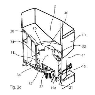
Figures 2a-2d show various sectional views of the embodiment
of the storage container according to the invention described in
greater detail here. The sorting mechanism 30 comprises a
projection 40 centered on the main body 31. The projection 40 is
realized as a single piece with the main body 31. In other
embodiments, the projection 40 can be realized as a separate
component and be screwed onto the main body 31, for example. The
projection 40 comprises a circular bottom surface and is
designed to be circularly cylindrical parallel to the rotational
axis of the sorting mechanism in a middle section 42.
In the embodiment shown, the projections 34 are of two-piece
construction and surround a gap 34a in axial direction. A
detention section 15a of the detention means 15 engages this gap
34a. The detention means 15 is arranged on the circularly
cylindrical section 11 of the housing 10, such that the
detention section 15a is always arranged over the dispensing
opening 21 (see in particular Figures 2c and 2d). This
arrangement of the detention section 15a of the detention means
15 ensures that drug portions arranged above the detention
section in a channel 35 are held back when a channel of the
sorting mechanism is oriented toward the dispensing opening 21.
Only the drug portion arranged below the retaining section is
dispensed when a channel is oriented toward the dispensing
opening.
8
CA 03043458 2019-05-09
The conical top surface 32 does not directly adjoin the
surface of the projections 34, but rather the projections are
offset downward, thus forming above the top surfaces of the
projections an annular space 38 defined on the inside by the
cylindrical main body 31 and on the outside by the cylindrical
section 11 of the housing 10. This annular surface facilitates
the guiding of drug portions to the channels 35, as is described
in greater detail using the following Figures.
The Figures 3a-3c show detailed views of the sorting
mechanism 30 of the storage container according to the
invention. The sorting mechanism 30 comprises a cylindrical main
body 31 with a conical top surface 32 and a main body casing
surface on which are realized multiple projections 34, which
define channels having a circumferential width KB and a radial
depth KT. In the embodiment shown, the projections are realized
as a single piece with the cylindrical main body 31. The outer
contours of the projections form a circularly cylindrical outer
casing surface 36 interrupted by channels 35 and represented as
a dashed-line circle in Figure 3b.
As Figures 3a and 3c show, the projections 34 have a
circumferentially running annular gap 34a in which, as was
described using Figures 2a-2d, a detention section of a
detention means can engage.
In the embodiment shown, the projections 34 are offset
downward relative to the conical top surface, thus forming above
the projections an annular space 38, which is defined on the
inside by the main body casing surface and on the outside by the
circularly cylindrical section 11 of the housing (see Figure 4).
Arranged on the conical top surface is a plurality of
elevations 39, which can support a tipping of a drug portion
into a channel. This is indicated in Figure 3c, in which a drug
portion 5 is indicated, namely lying on an elevation 39. Owing
to this elevation, the flat-shaped drug portion is tipped by the
"left" side into the annular space. The elevations thus
facilitate the drug portions being situated quickly and in a
simple manner in the annular space and finally the channels.
In addition, realized centered on the conical top surface is
a projection 40 with a circular bottom surface and a vertically
9
CA 03043458 2019-05-09
oriented circularly cylindrical section 42, which is completed
by a conical top surface 43. In the embodiment shown, the
vertical circularly cylindrical section 42 forms the outer
contour VAK/41 of the projection 40. The outer contour 41 of the
projection 40 determines the maximum radial distance VAmax
between the outer contour VAK and the outer casing surface 36
defined by the projections. Depending on the configuration of
the projection, this maximum radial distance can vary with the
angle (if the cylindrical section has for example, a square
bottom surface) or be uniform (as illustrated in the case of the
circularly cylindrical configuration).
Figure 3c shows in the lower section another coupling means
37 via which the sorting mechanism 30 is coupled to a drive (not
shown) by means of which the sorting mechanism can be rotated
incrementally for sorting drug portions. The coupling means 37
can be realized as a separate component or can be a single piece
with the main body 31 of the sorting mechanism.
According to the invention, the maximum radial distance
specified above is smaller than two times the circumferential
width Kg of a channel 35. As Figure 4 illustrates, this results
in no two drug portions 5 being able to situate themselves
radially next to one another in a flat manner on the conical top
surface, thereby preventing the drug portions from jamming on
the top surface.