Note: Descriptions are shown in the official language in which they were submitted.
-1-
DRUG DELIVERY SYSTEMS WITH SEALED AND STERILE
FLUID PATHS AND METHODS OF PROVIDING THE SAME
TECHNICAL FIELD
[0001] The present disclosure relates generally to the field of drug
delivery. In particular,
the present disclosure relates to drug delivery systems that include a sealed
and sterile fluid
path attached to a drug-loaded container. The disclosure further relates to
methods for
sterilizing the drug delivery systems without exposing the drug-loaded
container to harmful
sterilization parameters.
BACKGROUND
[0002] Conventional drug delivery systems are not optimized for post-
assembly
sterilization protocols because the sterilization modality (e.g., heat,
pressure, radiation, etc.)
can tend to degrade or destroy the drug(s) contained within such systems. The
inability to
provide a sealed and sterile fluid path attached to a drug-loaded container
requires that
conventional drug delivery systems provide the fluid path and drug-loaded
container as
separate components. A user is thus required to assemble these components into
a combined
device prior to drug administration. In addition to the increased costs
associated with
individually packaging and shipping these components, the time required to
assemble the drug
delivery system may result in significant inconvenience to the user. For
example, the time
required for an individual experiencing a severe allergic reaction to assemble
a drug delivery
system (e.g., epinephrine pens, etc.) may be the difference between life and
death. Similarly,
the time required for medical personnel to load an empty syringe with the
proper type and
dosage of drug may unnecessarily prolong the administration of the drug during
an emergency
situation.
Date Recue/Date Received 2021-09-20
-2-
[0003] A variety of advantageous medical outcomes may be realized by the
systems
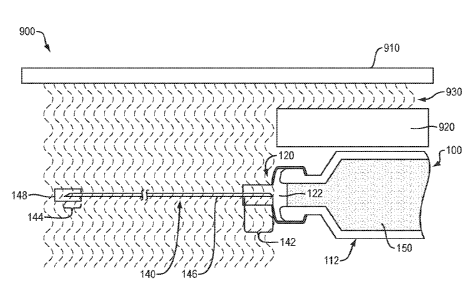
and/or methods of the present disclosure, which provide a drug delivery system
that includes a
sealed and sterile fluid path attached to a drug-loaded container.
BRIEF DESCRIPTION OF THE DRAWINGS
[0004] Non-limiting embodiments of the present disclosure are described by
way of
example with reference to the accompanying figures, which are schematic and
not intended to
be drawn to scale. In the figures, each identical or nearly identical
component illustrated is
typically represented by a single numeral. For purposes of clarity, not every
component is
labeled in every figure, nor is every component of each embodiment shown where
illustration
is not necessary to allow those of ordinary skill in the art to understand the
disclosure. In the
figures:
[0005] FIG. 1 provides a schematic view of a single-barrier drug delivery
system,
according to one embodiment of the present disclosure.
[0006] FIG. 2 provides a schematic view of an alternative single-barrier
drug delivery
system, according to one embodiment of the present disclosure.
[0007] FIG. 3 provides a schematic view of an alternative single-barrier
drug delivery
system, according to one embodiment of the present disclosure.
[0008] FIGS. 4A-4C provide schematic views of an alternative single-barrier
drug
delivery system, according to one embodiment of the present disclosure.
[0009] FIG. 5 provides a schematic view of an alternative single-barrier
drug delivery
system, according to one embodiment of the present disclosure.
[0010] FIG. 6 provides a schematic view of a double-barrier drug delivery
system,
according to one embodiment of the present disclosure.
Date Recue/Date Received 2021-09-20
-3-
[0011] FIG. 7 provides a schematic view of an alternative double-barrier
drug delivery
system, according to one embodiment of the present disclosure.
[0012] FIG. 8 provides a schematic view of an alternative double-barrier
drug delivery
system, according to one embodiment of the present disclosure.
[0013] FIG. 9 provides a schematic view of a sterilization system using a
single-barrier
drug delivery system, according to one embodiment of the present disclosure.
[0014] FIG. 10 provides a schematic view of an activated single-barrier
drug delivery
system, according to one embodiment of the present disclosure.
[0015] FIG. 11 provides a schematic view of a plunger drug delivery system,
according
to one embodiment of the present disclosure.
[0016] FIG. 12 provides a schematic view of an alternative plunger drug
delivery system,
according to one embodiment of the present disclosure.
[0017] FIGS. 13-14 provide schematic views of an activated plunger drug
delivery
system, according to one embodiment of the present disclosure.
[0018] FIGS. 15A-15B provide schematic views of a pre-loaded syringe drug
delivery
system, according to one embodiment of the present disclosure.
[0019] FIGS. 16A-18 provide schematic views of a double-barrier drug
delivery system
disposed within a shield assembly, according to one embodiment of the present
disclosure.
DETAILED DESCRIPTION
[0020] This disclosure presents various systems, components, and methods
related to a
drug delivery system and/or the sterilization of the drug delivery system.
Each of the
systems, components, and methods disclosed herein provides one or more
advantages over
conventional systems, components, and methods.
Date Recue/Date Received 2021-09-20
-4-
[0021] The present disclosure is not limited to the particular embodiments
described. The
terminology used herein is for the purpose of describing particular
embodiments only, and is
not intended to be limiting beyond the scope of the appended claims. Unless
otherwise
defined, all technical terms used herein have the same meaning as commonly
understood by
one of ordinary skill in the art to which the disclosure belongs.
[0022] Although embodiments of the present disclosure are described with
specific
reference to drug delivery, the systems and methods disclosed herein may be
used to provide
a sterile fluid path for a variety of sterile solutions, agents, materials,
biological and/or
pharmaceutical compositions from a variety of containers, cartridges,
syringes, pens, needles
and the like.
[0023] As used herein, the singular forms "a," "an," and "the" are intended
to include the
plural forms as well, unless the context clearly indicates otherwise. It will
be further
understood that the terms "comprises" and/or "comprising," or "includes"
and/or "including"
when used herein, specify the presence of stated features, regions, steps
elements and/or
components, but do not preclude the presence or addition of one or more other
features,
regions, integers, steps, operations, elements, components and/or groups
thereof.
[0024] As used herein, the terms "proximal" and "distal" refer to opposite
portions of the
devices or systems described herein, with "proximal" generally referring to
the portion closest
to the user of the devices or systems.
[0025] The present disclosure provides various drug delivery systems that
include a drug-
loaded container attached to a fluid path (e.g., transfer tube, needle,
syringe, etc.) by a cap
(e.g., plug, stopper, septum, etc.). As used herein, "drug" refers to any
therapeutic agent
administered to a user, as described herein. As used herein, "container"
refers to any suitable
space for containing a fluid drug. The cap may be configured to seal an
opening of the
Date Recue/Date Received 2021-09-20
-5-
container and establish sufficient separation between the fluid path and drug
such that
sterilization energy applied to a distal portion of the fluid path does not
contact or otherwise
act upon any portion of the drug.
[0026] Various embodiments provide drug delivery systems that can provide a
fluid path
and a drug container holding a liquid drug. The fluid path can be sterilized
by an energy
source without disturbing the liquid drug, which can be sterilized prior to
sterilizing the fluid
path. The fluid path can be coupled to the container such that after
sterilization, the drug
delivery system is immediately ready for use. Upon activation, for example
based on a user
input, the fluid path can be coupled to the stored liquid drug, thereby
providing a route for
delivery of the liquid drug to the user. The systems and methods described
herein obviates
the need for a user to transfer a liquid drug to a drug delivery system prior
to use and also
obviates the need for a user to assemble a drug delivery device prior to use ¨
accordingly,
embodiments provided herein provide fully assembled ready to use drug delivery
systems
through the arrangements and sterilizations techniques described herein.
Single-Barrier Systems
[0027] Referring to FIG. 1, in one embodiment, a drug delivery system 100
of the present
disclosure may include, in combination, a container 112, a cap 120 and a fluid
path 140. The
container 112 may include a body 114 and a neck 116 defining an interior
region 118. The
cap 120 may be disposed about at least a portion of the neck 116 to contain a
fluid drug 150
within the interior region 118. The fluid path 140 (e.g., transfer tube,
needle, syringe, etc.)
may define a lumen 146 and further include a first portion 142 with a
sharpened first end 141,
and a second portion 144 with a sharpened second end 143.
Date Recue/Date Received 2021-09-20
-6-
[0028] The cap 120 may include a "top hat" configuration secured to the
neck 116 by a
first crimp 126. For example, the cap 120 may include a first portion 122
configured to extend
at least partially into the neck 116, a second portion 123 configured to
overlap an end of the
neck 116 and a third portion 124 configured to extend distally beyond (e.g.,
away from) the
second portion 123. The neck 116 may include a flared portion 117 to provide a
surface
against which the first crimp 126 may be compressed to secure the second
portion 123 of the
cap 120 against the end of the neck 116. The first crimp 126 may include any
suitably
deformable and/or compressible material (e.g., metals, alloys, plastics,
rubbers, and the like),
as are known in the art. In various embodiments, the cap 120 may be secured to
the neck 116
by a variety of additional and/or alternative attachment mechanisms,
including, by way of
non-limiting example, corresponding threaded or luer-lock surfaces, adhesives,
glues, solders,
resins and the like.
[0029] The first portion 142 of the fluid path 140 may be disposed (e.g.,
embedded,
housed, etc.) within the third portion 124 of the cap 120 such that the
sharpened first end 141
is maintained a pre-determined distance away from the interface between the
fluid drug 150
and the first portion 122 of the cap 120. For example, the sharpened first end
141 of the fluid
path 140 may be separated from the fluid drug 150 by a distance of 10 cm or
more, more
preferably 20 cm or more, and even more preferably 30 cm or more. The third
portion 124 of
the cap 120 may also provide structural support to the first portion 142 of
the fluid path 140,
thereby preventing bending and/or moving of the fluid path during shipping,
storage and/or
use, which might comprise the integrity of the fluid-tight seal. In one
embodiment, the first
portion 142 of the fluid path 140 may be disposed within a channel 125 formed
within the
third portion 124 of the cap 120 to reduce or eliminate the potential for the
lumen 146 to
become plugged with a "core" of the cap 120 as the fluid path 140 is advanced
into the
Date Recue/Date Received 2021-09-20
-7-
interior region 118. Although the channel 125 is depicted as extending through
the length of
the third portion 124, in various embodiments the channel 125 may extend
through a portion
of the third portion 124. In addition, or alternatively, the channel 125 may
extend through the
third portion 124 into the first or second portions 122, 123 of the cap 120.
[0030] The second portion 144 of the fluid path 140 may be disposed (e.g.,
embedded,
housed, etc.) within a cover 148 such that the sharpened second end 143 is
shielded prior to
use. In one embodiment, a length of the second portion 144 may be sufficient
to penetrate the
dermal layer of a patient. For example, the second portion 144 of the fluid
path 140 may have
a length of 0.5 cm or more, more preferably 1.0 cm or more, and even more
preferably 2.0 cm
or more.
[0031] Referring to FIG. 2, in one embodiment, a drug delivery system 100
of the present
disclosure may further include a cap 220 with a "top hat" configuration like
that of FIG. 1,
with a first portion 222 configured to extend at least half-way (e.g.,
approximately 50%) into
the neck 116 to provide additional separation between the first portion 142
(and sharpened
first end 141) of the fluid path 140 and the fluid drug 150 within the
interior region 118 of the
container 112. In various embodiments, the first portion 222 may extend more
than half-way
into the neck 116, including, for example, extending completely (e.g. 100%)
into the neck.
[0032] Referring to FIG. 3, in one embodiment, a drug delivery system 100
of the present
disclosure may further include a cap 320 which includes a first portion 322
configured to
extend at least half-way (e.g., approximately 50%) into the neck 116, and a
second portion
323 configured to overlap an end of the neck 116, without a corresponding
third portion
extending distally beyond the second portion 323. The neck 116 may include a
flared portion
117 to provide a surface against which the first crimp 126 may be compressed
to secure the
second portion 323 of the cap 320 against the end of the neck 116.
Date Recue/Date Received 2021-09-20
-8-
[0033] Referring to FIGS. 4A-4C, in one embodiment, a drug delivery system
100 of the
present disclosure may further include a cap 420 with a "top hat"
configuration like that of
FIG. 1, with a third portion 424 configured to extend distally beyond (e.g.,
away from) a
second portion 423, and a first portion 422 configured to extend at least
partially into the neck
116. The third portion 424 may include a chamber 429 which defines an open
area or space
configured to house the first portion 142 of the fluid path 140 (FIG. 4A). The
open area or
space defined by the chamber 429 may provide various benefits as compared to a
completely
solid cap. For example, the chamber 429 may reduce the amount of resistance
required to
advance the first portion 142 of the fluid path 140 into the interior region
118 of the container
112 (FIG. 4B). In addition, the chamber 429 may extend proximally beyond the
sharpened
first end 141 of the fluid path 140 to further reduce or eliminate the
potential for the lumen
146 to become plugged with a "core" of the cap 420 as the fluid path 140 is
advanced in the
direction of the arrow 105 into the interior region 118. In addition, or
alternatively, the
chamber 429 may reduce the amount of resistance required to advance the first
portion 142 of
the fluid path 140 in the direction of the arrow 105 into the interior region
by moving to a
collapsed configuration (FIG. 4C). Although the chamber 429 is depicted
entirely within the
third portion 424 of the cap 420, in various embodiments, the chamber 429 may
extend into
the second portion 423 or first portion 422 of the cap 420.
[0034] Referring to FIG. 5, in one embodiment, a drug delivery system 100
of the present
disclosure may further include a cap 520 with a "top hat" configuration, which
includes a first
portion 522 configured to overlap an end of the neck 116, and a second portion
523
configured to extend distally beyond (e.g., away from) the neck 116, without
any portion of
the cap extending into the neck 116. The neck 116 may include a flared portion
117 to
Date Recue/Date Received 2021-09-20
-9-
provide a surface against which the first crimp 126 may be compressed to
secure the first
portion 522 of the cap 520 against the end of the neck 116.
[0035] In any of the embodiments of FIGS. 1-4C, the first portion 122, 222,
322, 422 of
the respective cap 120, 220, 320, 420, which extends into the neck 116 may
include one or
more compliant or semi-compliant materials, as are known in the art (e.g.,
polymers, rubbers,
silicones, etc.), which are sufficiently compressible to establish a friction
or interference fit
with an inner wall of the neck 116 with sufficient force to resist movement
(e.g., creeping) of
the cap, and provide a fluid-tight seal. In addition, at least the interface
surface of the first
portion 122, 222, 322, 422, 522 of the cap 120, 220, 320, 420, 520, which
contacts the fluid
drug 150 may preferably include a material which is compatible with (e.g.,
does not react with
or otherwise alter) the fluid drug 150.
[0036] As illustrated in FIG. 1, in any of the embodiments of FIGS. 1-5, a
length Li of the
first portion 142 of the fluid path 140 disposed within the cap 120 may be
greater than a
distance L2 between the sharpened first end 141 and an interface of the fluid
drug 150 and the
first portion 122 of the cap 120. As will be understood by those of skill in
the art, the length
Li may be sufficient to allow only the first portion 142 of the fluid path 140
embedded within
the cap 120 to be placed in contact with the fluid drug 150 when the fluid
path 140 is
advanced, thereby preventing a potentially non-sterile portion of the fluid
path 140 extending
distally beyond the cap 120 from contacting the fluid drug 150. As will be
understood by one
of skill in the art, single-barrier system embodiments of FIGS. 1-5 may
include a cap to
maintain separation between the portion of the fluid path disposed within the
cap (including
the first sharpened end) and the fluid drug inside the container.
Double-Barrier Systems
Date Recue/Date Received 2021-09-20
-10-
[0037] Referring to FIG. 6, in one embodiment, a drug delivery system 200
of the present
disclosure may include, in combination, a container 212, a septum 630, a cap
620 and a fluid
path 240. The container 212 may include a body 214 and a neck 216 defining an
interior
region 218. The septum 630 may be disposed about at least a portion of the
neck 216 to retain
a fluid drug 250 (e.g., drug, biological composition, pharmaceutical
composition, etc.) within
the interior region 218. The cap 620 may be disposed against at least a
portion of the septum
630. The fluid path 240 (e.g., transfer tube, needle, syringe, etc.) may
define a lumen 246 and
further include a first portion 242 with a sharpened first end 241, and a
second portion 244
with a sharpened second end 243.
[0038] The septum 630 may be secured to the neck 216 by a first crimp 626.
For example,
the septum 630 may include a first portion 632 configured to extend at least
partially into the
neck 216, and a second portion 633 configured to overlap an end of the neck
216. The neck
216 may include a flared portion 217 to provide a surface against which the
first crimp 626
may be compressed to secure the second portion 633 of the septum 630 against
the end of the
neck 216. The first crimp 626 may include any suitably deformable and/or
compressible
material (e.g., metals, alloys, plastics, rubbers, and the like), as are known
in the art. Although
the first portion 632 of the septum 630 is depicted as extending into a
portion of the neck 216,
in various embodiments, the first portion 632 may extend into the entire
portion (e.g., 100%)
of the neck, less than the entire portion of the neck (e.g., approximately
50%), no portion
(e.g., 0%) of the neck, or any variation thereof. The septum 630 may include
one or more
compliant or semi-compliant materials, as are known in the art (e.g.,
polymers, rubbers,
silicones, etc.), which are sufficiently compressible (e.g., crimpable) to
establish a fluid-tight
seal between an inner surface of the first crimp 626 and the end of the neck
216. In addition,
at least the portion (e.g., interface surface) of the septum 630, which
contacts a fluid drug 250
Date Recue/Date Received 2021-09-20
-1 I -
may preferably include a material which is compatible with (e.g., does not
react with or
otherwise alter) the fluid drug 250.
[0039] The cap 620 may be secured to the neck 216 by a second crimp 627
disposed
around a portion of the first crimp 626. For example, the cap 620 may include
a "top hat"
configuration which includes a first portion 622 configured to overlap at
least a portion of the
septum 630 and the first crimp 626, and a second portion 623 configured to
extend distally
beyond (e.g., away from) the first portion 622. The second crimp 627 may
include any
suitably deformable and/or compressible material (e.g., metals, alloys,
plastics, rubbers, and
the like), as are known in the art. In various embodiments, the cap 620 may be
secured to the
septum 630 by a variety of additional and/or alternative attachment
mechanisms, including,
by way of non-limiting example, corresponding threaded or luer-lock surfaces,
adhesives,
glues, solders, resins and the like.
[0040] The first portion 242 of the fluid path 240 may be disposed (e.g.,
embedded,
housed, etc.) within the second portion 623 of the cap 620 such that the
sharpened first end
241 is maintained a pre-determined distance away from the interface between
the fluid drug
250 and the first portion 632 of the septum 630. For example, the sharpened
first end 241 of
the fluid path 240 may be separated from the fluid drug 250 by any distance,
including but not
limited to, 10 cm or more, more preferably 20 cm or more, and even more
preferably 30 cm or
more. The second portion 623 of the cap 620 may also provide structural
support to the first
portion 242 of the fluid path 240, thereby preventing bending and/or moving of
the fluid path
during shipping, storage and/or use, which might comprise the integrity to the
fluid-tight seal.
[0041] The second portion 244 of the fluid path 240 may be disposed (e.g.,
embedded,
housed, etc.) within a cover 248 such that the sharpened second end 243 is
shielded prior to
use. In one embodiment, a length of the second portion 244 may be sufficient
to penetrate the
Date Recue/Date Received 2021-09-20
-12-
dermal layer of a patient. For example, the second portion 244 of the fluid
path 240 may have
a length of 0.5 cm or more, more preferably 1.0 cm or more, and even more
preferably 2.0 cm
or more.
[0042]
Referring to FIG. 7, in one embodiment, a drug delivery system 200 of the
present
disclosure may further include a cap 720 with a "top hat" configuration like
that of FIG. 6,
which includes a first portion 722 configured to overlap at least a portion of
the septum 730
and the first crimp 726, and a second portion 723 configured to extend
distally beyond (e.g.,
away from) the first portion 722. The first and second portions 722, 723 may
include a
chamber 729 which defines an open area or space configured to house the first
portion 242 of
the fluid path 240. The open area or space defined by the chamber 729 may
provide various
benefits as compared to a completely solid cap. For example, the chamber 729
may reduce the
amount of resistance required to advance the first portion 242 of the fluid
path 240 into the
interior region 218 of the container 212. In addition, as compared to
embodiments in which
the first portion of the fluid path is embedded within the cap, the chamber
729 may reduce or
eliminate the potential for the lumen 246 to become plugged with a "core" of
the cap 720 as
the fluid path 240 is advanced into the interior region 218. In addition, or
alternatively, the
chamber 729 may reduce the amount of resistance required to advance the first
portion 242 of
the fluid path 240 into the interior region 218 by moving to a collapsed
configuration (not
shown). Although the chamber 729 is depicted as extending between the first
and second
portions 722, 723, in various embodiments, the chamber may be formed entirely
within the
second portion 723 of the cap 720. Referring to FIG. 8, in one embodiment, a
drug delivery
system 200 of the present disclosure may further include one or more 0-rings
828 disposed
between the septum 830 and first portion 822 of a cap 820 to maintain a fluid-
tight seal about
the neck 216.
Date Recue/Date Received 2021-09-20
-13-
[0043] In any of the embodiments of FIGS. 1-8, the cap 120, 220, 320, 420,
520, 620,
720, 820, may include a dual-durometer material. For example, a portion of the
cap may
include a high durometer material, e.g., to provide additional support to the
fluid path and/or
provide a firm surface against which the first or second crimps may press for
improved
sealing. Another portion of the cap may include a low durometer material,
e.g., to reduce or
eliminate coring and/or provide improved sealing as the fluid path is advanced
into the
interior region of the container. In addition, at least a portion of the cap
may include a
material that is compatible with the specific sterilization modality employed
(e.g., does not
degrade or otherwise break down), as discussed below.
[0044] As illustrated in FIG. 6, in any of the embodiments of FIGS. 6-8, a
length Li of the
first portion 242 of the fluid path 240 disposed within the cap 220 may be
greater than a
distance L2 between the sharpened first end 241 and an interface of the fluid
drug 250 and the
first portion 632 of the septum 630. As will be understood by those of skill
in the art, the
length Li may be sufficient to allow only the first portion 242 of the fluid
path 240 embedded
within the cap 220 to be placed in contact with the fluid drug 250 when the
fluid path 240 is
advanced, thereby preventing a potentially non-sterile portion of the fluid
path 240 extending
distally beyond the cap 220 from contacting the fluid drug 250. As will be
understood by one
of skill in the art, double-barrier system embodiments of FIGS. 6-8 may
include a cap and/or
septum to maintain separation between the portion of the fluid path disposed
within the cap
(including the first sharpened end) and the fluid drug inside the container.
[0045] Although the drug delivery systems disclosed herein generally
include a cap
(FIGS. 1-5) or cap and septum (FIGS. 6-8) attached to the neck of a container,
in various
embodiments the container may include a variety of shapes and or
configurations (e.g.,
cartridges, vials, pens, etc.) that do not necessarily include a neck.
Date Recue/Date Received 2021-09-20
-14-
Sterilization Protocols
[0046] In one embodiment, any of the drug delivery systems disclosed herein
may
undergo a sterilization protocol to provide a sealed and sterile fluid path.
Referring to FIG. 9,
a drug delivery system 100, 200 may be placed within a sterilization system
900, which
includes an energy source 910 and a shield 920. In various embodiments, the
energy source
910 may emit x-ray, y-ray or electrical-beam (e.g., e-beam) energy. The shield
920 may
include a material with a suitable composition and/or thickness to prevent
(e.g., block) energy
emitted 930 from the energy source 910 from passing (e.g., penetrating)
therethrough. In
various embodiments, the shield may comprise a material which does not emit or
generate
energy (e.g. x-rays, etc.) when acted upon by an energy source (or limits such
emissions). For
example, the shield may be formed partially or entirely of aluminum having a
thickness of
approximately 30mm or more.
[0047] The energy source 910 and shield 920 may be positioned relative to
each other
such that a portion of the energy emitted 930 from energy source 910 contacts
and is blocked
by the shield 920, and another portion of the energy emitted 930 is direct
beyond an end of the
shield 920 and remains unblocked. Alternatively, the shield 920 may include an
opening (not
shown) such that the energy emitted 930 from the energy source 910 contacts
and is blocked
by the shield 920 on either side of the opening. By way of example, the drug
delivery system
100 may be positioned within the sterilization system 900 such that the entire
portion of the
container 112 which contains the fluid drug 150, and at least part of the
first portion 122 of
the cap 120, is aligned with (e.g., underneath) the shield 920 and protected
from the energy
emitted 930 from the energy source 910.
[0048] The remaining portion of the drug delivery system 100, including the
cover 148,
entire fluid path 140, and at least the portion of the cap 120 disposed around
the first portion
Date Recue/Date Received 2021-09-20
-15-
of the 142 of the fluid path 140, is not aligned with (e.g., extends beyond)
the shield 920.
Upon activation of the energy source 910, the emitted energy 930 passes
through and
sterilizes the entire unshielded portion of the drug delivery system 100,
including the first
portion 142 of the fluid path 140 embedded within the cap 120, the second
portion 144 of the
fluid path 140 embedded within the cover 148 and the lumen 146 extending
therebetween,
thereby providing a sterile and sealed fluid path. Since the energy source 910
does not
generate heat, the drug delivery system 100 may remain within the
sterilization system 900 as
long as required for sterilization of the entire fluid path 140 without the
need for any form of
refrigeration, light and/or humidity control systems. As explained above,
various cap (and
septum) configurations may be used to increase or decrease the distance
between the portion
of the fluid path embedded within the cap and the fluid drug within the
container depending,
e.g., on the preferred target surface area for the energy source, the duration
of the sterilization
protocol and/or the stability requirements of the specific fluid. Although
FIG. 9 depicts a drug
delivery system 100 of the present disclosure undergoing a sterilization
protocol, in various
embodiments, any of the drug delivery systems disclosed herein 200, 300, 400
may undergo a
sterilization protocol in a sterilization system of FIG. 9 or FIGS. 16A-18
(discussed below).
[0049] In various embodiments herein, the drug stored in the container can
be exposed to
limited amounts of the emitted energy (e.g., radiation or electron beam). The
amount of
exposure can be less than a critical level and/or less than a level that can
cause substantial
degradation of the drug stored in the container.
[0050] As will be understood by one of skill in the art, the drug delivery
systems,
sterilization systems and protocols described herein may provide a number of
advantages over
conventional drug delivery systems, sterilization systems and modalities. By
way of a non-
liming example, the disclosed sterilization systems and protocols may be
temperature
Date Recue/Date Received 2021-09-20
-16-
independent, thereby allowing sterilization to be performed in a cold (e.g.,
refrigerated)
environment to prevent degradation or inactivation of temperature sensitive
drugs, biological
and/or pharmaceutical compositions. In addition, the ability of the disclosed
sterilization
systems and protocols to be performed at the ideal temperature for a specific
drug, biological
and/or pharmaceutical composition, may eliminate the need for special
formulations to be
compatible. The disclosed drug delivery devices, sterilization systems and
protocols may also
eliminate the need for specialized environmental conditions (e.g., vacuum
sealed containers,
etc.). The disclosed drug delivery devices, sterilization systems and
protocols may also
prevent exposure of the biological and/or pharmaceutical composition, as well
as certain
material components of the drug-delivery system, to the specific sterilization
modality (x-ray,
y-ray or electrical-beam (e.g., e-beam) energy). The disclosed sterilization
systems and
protocols may also be compatible with conventional containers, thereby
eliminating the need
to exchange containers during the filling or finishing process.
[0051] Referring to FIG. 10, in use and by way of example, a user may
"activate" a drug
delivery system by proximally advancing the fluid path 140 in the direction of
the arrow 105
towards the container 112 such that the sterile first portion 142 of the fluid
path 140 housed
within the cap 120 enters the interior region 118. With the lumen 146 of the
fluid path 140 in
contact with the fluid drug 150, the sterile second portion 144 of the fluid
path 140 may be
advanced through the cover 148 and dermal layer of the patient. Since only the
first and
second portions 142, 144 of the fluid path 140 penetrate the interior region
118 of the
container 112 and the dermal layer, respectively, any non-sterile portion of
the fluid path 140
(e.g., between the cap 120 and cover 148) is prevented from penetrating either
the patient or
the container. In one embodiment, the steps of advancing the first portion 142
of the fluid path
140 into the interior region 118 of the container 112, and advancing the
second portion 144 of
Date Recue/Date Received 2021-09-20
-17-
the fluid path 140 through the dermal layer, may occur almost simultaneously.
For example, a
user may employ a "jabbing" or "stabbing" motion to advance the sterile second
portion 144
of the fluid path 140 into the dermal layer. The force exerted on the fluid
path 140 by this
"jabbing" or "stabling" motion may simultaneously drive the sterile first
portion 142 of the
fluid path 140 into the interior region 118 of the container 112. In one
embodiment, the
container 112 may be pressurized such that the proper dosage of fluid drug 150
is
automatically delivered through the lumen 146 of the fluid path 140 and into
the patient.
Alternatively, the container 112 may include a delivery mechanism, e.g.,
plunger, etc. (not
shown) which the user may actuate as necessary to deliver the fluid drug 150
through the
lumen 146 of the fluid path 140 and into the patient. Alternatively, the drug
delivery system
may include an inertia driven system that includes, e.g., a safety and trigger
mechanism
configured to automatically drive the first portion 142 of the fluid path 140
into the interior
region 118 of the container and/or drive the second portion 144 of the fluid
path 140 through
the dermal layer. In various embodiments, the drive/delivery mechanism which
conveys
movement of the fluid path in either (or both) directions may include an
electromechanical or
mechanical system.
Assembly Protocols
[0052] Prior to implementing the sterilization protocol, the drug delivery
systems of the
present disclosure may undergo various assembly protocols using aseptic
techniques, as are
known in the art. For example, a drug delivery system 100 that includes a
single-barrier may
be assembled by sterilizing the container 112 with ethylene oxide, and
sterilizing the cap 120
with steam or y-irradiation. In some embodiments, the cap may comprise a gas-
permeable
material compatible with nitrous oxide (NO2) sterilization, which may be
beneficial for
sterilizing a cap that includes an inner chamber. The sterilized container 112
may then be
Date Recue/Date Received 2021-09-20
-18-
filled with a sterile fluid drug 150 under aseptic conditions. The sterilized
cap 120 may then
be positioned on the neck 116 of the fluid-filled container 112 and secured
using the first
crimp 126. Alternatively, the sterilized cap 120 may be attached to an empty
sterilized
container 112, as outlined above, and the container 112 filled with sterile
fluid drug 150
through the cap 120 using a sterile syringe. The first portion 142 of the
fluid path 140 may
then be positioned (e.g., inserted) a predetermined distance within the cap
120, and the second
portion 144 of the fluid path 140 may be positioned a predetermined distance
within a cover
148.
[0053] A drug delivery system 200 that includes a double-barrier system may
be
assembled by sterilizing the container 212 with ethylene oxide, and
sterilizing the cap 620,
720, 820 and septum 630, 730, 830 with steam or y-irradiation. The container
212 may then
be filled with sterile fluid drug 250 under aseptic conditions. The sterilized
septum 630, 730,
830 may then be positioned on the neck 216 of the fluid-filled container 212
and secured
using the first crimp 626. Alternatively, the sterilized septum 630, 730, 830
may be attached
to an empty sterilized container 212, as outlined above, and the container 212
filled with the
fluid drug 250 through the septum 630, 730, 830 using a sterile syringe. The
sterilized cap
620, 720, 820 may then be positioned on or above the septum 630, 730, 830 and
secured using
the second crimp 627. The first portion 242 of the fluid path 240 may then be
positioned (e.g.,
inserted) a predetermined distance within the cap 620, 720, 820 and the second
portion 244 of
the fluid path 240 may be positioned a predetermined distance within the cover
248. The fully
assembled drug delivery system 100, 200 may then undergo a sterilization
protocol to provide
a sealed and sterile fluid path, as discussed above.
Plunger Systems
Date Recue/Date Received 2021-09-20
-19-
[0054] In various embodiments, a drug delivery system of the present
disclosure may
include a needle path that does not extend through the cap and/or septum
positioned at the
neck of the container, but instead extends through a cap and plunger located
at the opposite
end of the container. The container may be filled under aseptic conditions by
introducing the
needle of a separate syringe (not shown) through the septum into the interior
region 118.
[0055] Referring to FIG. 11, in one embodiment, a drug delivery system 300
of the
present disclosure may include, in combination, a container 312, a cap 1120, a
plunger 1160
and a fluid path 340. The container 312 may include a body 314 defining an
interior region
318. The cap 1120 may be disposed within an end portion of the container 312.
The fluid path
340 (e.g., transfer tube, needle, syringe, etc.) may define a lumen 346 and
further include a
first portion 342 with a sharpened first end 341, and a second portion 344
with a sharpened
second end 343. The cap 1120 may include one or more semi-compliant materials,
as are
known in the art (e.g., polymers, rubbers, silicones, etc.), which are
sufficiently compressible
to establish a friction or interference fit with an inner wall of the
container 312 with sufficient
force to resist movement of the cap, and provide a fluid-tight seal. The cap
1120 may further
include one or more 0-rings 1128 disposed between the cap 1120 and inner wall
of the
container 312 to maintain the fluid-tight seal. A septum 1130 may be disposed
within, and
extend through, a central portion of the cap 1120. The septum 1130 may be
permanently
affixed within the cap 1120 using suitable adhesives, glues and/or resins, as
are known in the
art.
[0056] Alternatively, in place of a septum, the cap 1120 may include a dual-
durometer
material such that, e.g., an outer portion of the cap 1120 is formed of a high-
durometer
material for improved compression against the inner wall of the container 312,
and an inner
portion of the cap 1120 is formed of a low-durometer material to reduce or
eliminate coring
Date Recue/Date Received 2021-09-20
-20-
and/or provide improved sealing around the fluid path 340. The cap 1120 and/or
septum 1130
may also provide structural support to the first portion 342 of the fluid path
340, thereby
preventing bending and/or moving of the fluid path during shipping, storage
and/or use, which
might comprise the integrity of the fluid-tight seal. In addition, at least a
portion of the
plunger 1160, cap 1120 and/or septum 1130 may include a material that is
compatible with
the specific sterilization modality employed (e.g., does not degrade or
otherwise break down),
as discussed above.
[0057] The plunger 1160 may be slidably disposed within the container 312
proximal to
the septum to retain a fluid drug 350 (e.g., drug, biological composition,
pharmaceutical
composition, etc.) within the interior region 318. The first portion 342 of
the fluid path 340
may be disposed within an open space 362 between the cap 1120 and plunger 1160
such that
the sharpened first end 341 is maintained a predetermined distance away from
the interface
between the fluid drug 350 and the plunger 1160. For example, the sharpened
first end 341 of
the fluid path 340 may be separated from the fluid drug 350 by a distance of
10 cm or more,
more preferably 20 cm or more, and even more preferably 30 cm or more. The
second portion
344 of the fluid path 340 may be disposed (e.g., embedded, housed, etc.)
within a cover 348
such that the sharpened second end 343 is shielded prior to use. In one
embodiment, a length
of the second portion 344 may be sufficient to penetrate the dermal layer of a
patient. For
example, the second portion 344 of the fluid path 340 may have a length of 0.5
cm or more,
more preferably 1.0 cm or more, and even more preferably 2.0 cm or more.
[0058] Referring to FIG. 12, in one embodiment, the first portion 342 of
the fluid path
340 may extend through the open space 362 into a portion of the plunger 1160
to provide
additional support and/or protection to the fluid path.
Date Recue/Date Received 2021-09-20
-21-
[0059] In various embodiments, the drug delivery system 300 may be
positioned within a
sterilization system, as discussed above, such that the entire portion of the
container 312
which contains the fluid drug is aligned with (e.g., underneath) a shield and
protected from
energy emitted from an energy source. The remaining portion of the drug
delivery system
300, including the first portion 342 of the fluid path 340 and at least a
portion of the plunger
1160, is not aligned with (e.g., extends beyond) the shield. Upon activation
of the energy
source, the emitted energy passes through and sterilizes the entire unshielded
portion of the
drug delivery system 300 (e.g., the first portion 342 of the fluid path 340
and a portion of the
plunger 1160), thereby providing a sterile and sealed fluid path. In various
embodiments, the
first portion 342 of the fluid path 340 can be positioned within a portion of
the plunger 1160.
In such embodiments, the first portion 342 of the fluid path 340 can be
partially embedded in
the plunger 1160. The first portion 342 of the fluid path 340 can be exposed
to emitted
energy from the energy source for sterilization. After sterilization, upon
activation, the first
portion 342 of the fluid path 340 can pierce through the remaining portion of
the plunger
1160.
[0060] The individual components (e.g., container 312, cap 1120, septum
1130 and
plunger 1160) of the drug delivery system 300 of FIGS. 11 or 12 may be
individually
sterilized, assembled and filled with fluid drug 350 using aseptic techniques,
as described
above. Similarly, the drug delivery systems 300 of FIGS. 11 or 12 may undergo
a sterilization
protocol which shields the portion of the container 312 filled with the fluid
drug 350 and
exposes the full length of the fluid path 340 to sterilization energy to
provide a sealed and
sterile fluid path 340, as described above.
[0061] Referring to FIG. 13, in use and by way of example, a user may
"activate" a drug
delivery system 300 by proximally advancing the fluid path 340 in the
direction of the arrow
Date Recue/Date Received 2021-09-20
-22-
105 towards the container 312 such that the sterile first portion 342 of the
fluid path 340
housed within the open space 362 (FIG. 11) or plunger 1160 (FIG. 12) enters
the interior
region 318. Referring to FIG. 14, with the lumen 346 the fluid path 340 in
contact with the
fluid drug 350, the sterile second portion 344 of the fluid path 340 may be
advanced in the
direction of the arrow 105 through the cover 348 to penetrate the dermal layer
of the patient,
and the plunger 1160 and fluid path 340 advanced proximally to force the fluid
drug 350
through the lumen 346 of the fluid path 340 into the patient. Since only the
first and second
portions 342, 344 of the fluid path 340 penetrate the interior region 318 of
the container 312
and dermal layer, respectively, any non-sterile portion of the fluid path 340
(e.g., between the
cap 320 and cover 348) is prevented from penetrating either the patient or the
container.
[0062] In any of the embodiments of FIGS. 11 and 12, a length Li of the
first portion 342
of the fluid path 340 disposed within the open space 362 (FIG. 11) or plunger
1160 (FIG. 12)
may be greater than a distance L2 between the sharpened first end 341 and an
interface of the
fluid drug 350 and the plunger 1160. As will be understood by those of skill
in the art, the
length Li may be sufficient to allow only the first portion 342 of the fluid
path 340 embedded
within the open space 362, or plunger 1160, to be placed in contact with the
fluid drug 350
when the fluid path 340 is advanced proximally, thereby preventing a
potentially non-sterile
portion of the fluid path 340 extending distally beyond the open space 362 or
plunger 1160
from contacting the fluid drug 350.
Pre-Loaded Syringe Systems
[0063] Referring to FIG. 15A, in one embodiment, a drug delivery system 400
of the
present disclosure may include, in combination, a container 1512, a cap 1520
and a fluid path
440. The container 1512 may include, e.g., a standard syringe comprising a
needle 1516 in
fluid communication with an interior region 1518 of the container and a
plunger 1560 slidably
Date Recue/Date Received 2021-09-20
-23-
disposed within the interior region 1518. The needle 1516 may define a lumen
1546 and
further include a distal portion 1542 with a sharped end 1541. The distal
portion 1542 of the
needle 1516 may be embedded within a first portion 1522 of the cap 1520. The
fluid path 440
(e.g., transfer tube, needle, syringe, etc.) may define a lumen 446 and
further include a first
portion 442 with a sharpened first end 441, and a second portion 444 with a
sharpened second
end 443. The first portion 442 of the fluid path 440 may extend through a
second portion 1523
of the cap 1520 and into a chamber 1529 within the cap 1520. The second
portion 444 of the
fluid path 440 may be disposed (e.g., embedded, housed, etc.) within a cover
448 such that the
sharpened second end 443 is shielded prior to use.
[0064] The container 1512 may be sterilized using ethylene oxide, steam or
7-irradiation
and loaded with a sterile fluid drug 450 using aseptic techniques, as
described above. The
distal portion 1542 of the needle 1516 and first portion 442 of the fluid path
440 may then be
positioned within the first portion 1522 and chamber 1529 of the cap 1520,
respectively. Once
assembled, the drug delivery system 400 may undergo a sterilization protocol
to provide a
sealed and sterile fluid path 440 and/or sterile needle 1516, as described
above.
[0065] For example, the drug delivery system 400 may be placed within a
sterilization
system 900, which includes an energy source 910 and a shield 920. In various
embodiments,
the energy source 910 may emit x-ray, 7-ray or electrical-beam (e.g., e-beam)
energy. The
shield 920 may include a material with a suitable composition and/or thickness
to prevent
(e.g., block) energy emitted 930 from the energy source 910 from passing
(e.g., penetrating)
therethrough. In various embodiments, the shield 920 may comprise a material
which does not
emit or generate energy (e.g. x-rays, etc.) when acted upon by an energy
source (or limits
such emissions). For example, the shield 920 may be formed partially or
entirely of aluminum
having a desired thickness such as, for example, a thickness of approximately
30mm or more.
Date Recue/Date Received 2021-09-20
-24-
[0066] The energy source 910 and shield 920 may be positioned relative to
each other
such that a portion of the energy emitted 930 from energy source 910 contacts
and is blocked
by the shield 920, and another portion of the energy emitted 930 is directed
beyond an end of
the shield 920 and remains unblocked. By way of example, the drug delivery
system 400 may
be positioned within the sterilization system 900 such that the entire portion
of the container
1512 which contains the fluid drug is aligned with (e.g., underneath) the
shield 920 and
protected from the energy emitted 930 from the energy source 910. The
remaining portion of
the drug delivery system 400, including the distal portion 1542 of the needle
1516, the cap
1520, the fluid path 440 and cover 448, is not aligned with (e.g., extends
beyond) the shield
920. Upon activation of the energy source 910, the emitted energy 930 passes
through and
sterilizes the entire unshielded portion of the drug delivery system 400,
thereby providing a
sterile and sealed fluid path. Since the energy source 910 does not generate
heat, the drug
delivery system 400 may remain within the sterilization system 900 as long as
required for
sterilization of the entire fluid path 440 without the need for any form of
refrigeration, light
and/or humidity control systems.
[0067] Referring to FIG. 15B, in use and by way of example, a user may
"activate" a drug
delivery system 400 by distally advancing the container 1512 in the direction
of the arrow 105
towards the cap 1520 such that sterile distal portion 1542 of the needle 1516
housed within
the first portion 1522 of the cap 1520 enters the and chamber 1529, thereby
placing the
respective lumens 1546, 446 of the needle 1516 and fluid path 440 in fluid
communication.
The second portion 444 of the fluid path 440 may be inserted through the
dermal layer, and
the plunger 1560 depressed such that fluid drug 450 flows through the lumen
1546 of needle
1516 into the sterile chamber 1529 and through the sterile lumen 446 of the
fluid path 440
into the patient.
Date Recue/Date Received 2021-09-20
-25-
[0068] In any of the embodiments of FIGS. 1-8, 11, 12 and 15A-15B, the
cover 148, 248,
348, 448 may be removed from the second portion 144, 244, 344, 444 of the
fluid path 140,
240, 340, 440 prior to penetrating the dermal layer of a patient.
Alternatively, the second
portion 144, 244, 344, 444 of the fluid path 140, 240, 340, 440 may be
advanced through the
cover 148, 248, 348, 448 and through the dermal layer of a patient. The drug
delivery systems
100, 200, 300, 400 may include a depth setting such that only the second
portion 144, 244,
344, 444 of the fluid path 140, 240, 340, 440 penetrates the dermal layer,
thereby preventing a
potentially non-sterile portion of the fluid path 140, 240, 340, 440 extending
proximally
beyond the cover 148, 248, 348, 448 from penetrating the dermal layer of the
patient.
Shield Assemblies
[0069] With reference to the sterilization system 900 schematically
depicted in FIG. 9
(above), in one embodiment, the shield 920 may be configured to block
sterilization energy
emitted from an energy source 910 along or above one side of the drug delivery
system.
Referring to FIGS. 16A-18, in one embodiment, the present disclosure may
include a shield
assembly 1600 configured to provide 360 degrees of shielding to a drug
delivery system
disposed therein. In various embodiments, the shield assembly 1600 may
include, in
combination, first and second interlocking components 1610, 1620 (interlocking
component
1620 not shown in the overhead view of the assembly 1600 in FIG. 16A). The
first
component 1610 may include a first window or opening 1615 extending through a
width
thereof, and the second component 1620 (e.g., positioned under the first
component 1610)
may include a corresponding second window or opening 1625 (see FIG. 17)
extending
through a width thereof.
[0070] Each of the first and second windows 1615, 1625 may be configured to
define a
contiguous opening 1630 (see FIG. 18) through the assembled shield assembly
1600, e.g.,
Date Recue/Date Received 2021-09-20
-26-
when the first and second interlocking components 1610, 1620 are locked
together. One or
both of the first or second components 1610, 1620 may be dimensioned to
securely receive
the outer surface of a portion of a drug delivery system such that the portion
of the drug
delivery system to be sterilized (e.g., the entire length of the fluid path
240 and portion of the
cap 620 and/or septum 630) extends into the contiguous opening 1630, and the
portion of the
drug delivery system to be shielded from an energy source is covered, encased
or otherwise
blocked around an entire circumference thereof by the shield assembly 1600.
[0071] As described above, the shield assembly 1600 may be formed partially
or entirely
of a material (e.g., aluminum) with a sufficient thickness (e.g.,
approximately 30mm or more)
to prevent (e.g., shield) energy emitted from the energy source from acting
upon the fluid
drug and/or material components of the drug delivery system which may degrade
or otherwise
become compromised by such energy, and without emitting x-ray's or other
deleterious
energy when acted upon by the energy source (or limiting such emissions). In
various
embodiments, with the drug delivery system previously loaded with a fluid drug
under aseptic
conditions (as discussed above) and secured within an assembled shield
assembly 1600, the
entire shield assembly 1600 may be placed within a suitable chamber and
exposed to an
energy source to provide 360 degrees of sterilization of the portion of the
drug delivery
system extending through the contiguous opening 1630, while providing complete
shielding
of the remaining portion of the drug delivery system housed within the
interlocked first and
second components 1610, 1620.
[0072] As will be understood by those of skill in the art, the entire
shield assembly 1600
with a drug delivery system disposed therein may be exposed to a given
sterilization modality
for a variety of times as previously determined to provide complete
sterilization of the
exposed portions thereof (e.g., extending through the contiguous opening
1630). In one
Date Recue/Date Received 2021-09-20
-27-
embodiment, the energy source may rotate around the shield assembly 1600 to
provide
optimal exposure to the sterilization energy. Alternatively, the energy source
may remain in a
fixed position, and the shield assembly rotated to provide optimal exposure to
the sterilization
assembly. In various embodiments, one or more energy sources may be used.
Further, the
assembly 1600 can exposed to a given sterilization modality in bulk ¨ that is,
multiple
assemblies 1600 can be together grouped and sterilized at the same time. Any
of the drug
delivery devices described herein can be used with the assembly 1600.
[0073] The following examples pertain to additional embodiments:
[0074] Example 1 is a method for providing a sealed and sterile fluid path,
comprising
exposing a drug delivery system to an energy source, the drug delivery system
comprising a
container comprising a fluid drug, a cap disposed about an opening of the
container, and a
fluid path defining a lumen, the fluid path comprising a first portion
disposed within a portion
of the cap, and a second portion disposed within a cover, wherein energy
emitted from the
energy source passes through and sterilizes the fluid path, and does not pass
through any
portion of the container comprising the fluid drug.
[0075] Example 2 is an extension of example 1 or any other example
disclosed herein,
wherein a length of the first portion of the fluid path disposed within the
cap is greater than a
distance between a sharpened first end of the fluid path and an interior
region of the container.
[0076] Example 3 is an extension of example 1 or any other example
disclosed herein,
wherein the energy emitted from the energy source is selected from the group
consisting of x-
ray energy, y-ray energy and electrical-beam energy.
[0077] Example 4 is an extension of example 1 or any other example
disclosed herein,
wherein the cap is configured to form a fluid-tight seal about the opening of
the container.
Date Recue/Date Received 2021-09-20
-28-
[0078] Example 5 is an extension of example 1 or any other example
disclosed herein,
further comprising a septum disposed between the cap and the opening of the
container.
[0079] Example 6 is a method for providing a sealed and sterile fluid path,
comprising
exposing a drug delivery system to an energy source, the drug delivery system
comprising a
container comprising a fluid drug, a cap disposed about an opening of the
container, a plunger
slidably disposed within the container and proximal to the cap, wherein the
cap and plunger
are separated by an open space, and a fluid path defining a lumen, the fluid
path comprising a
first portion extending through the cap and disposed within the open space,
and a second
portion disposed within a cover, wherein energy emitted from the energy source
passes
through and sterilizes the fluid path, and does not pass through any portion
of the container
comprising the fluid drug.
[0080] Example 7 is an extension of example 6 or any other example
disclosed herein,
wherein a length of the first portion disposed within the open space is
greater than a distance
between a sharpened first end of the fluid path and an interior region of the
container.
[0081] Example 8 is an extension of example 6 or any other example
disclosed herein,
wherein the energy emitted from the energy source is selected from the group
consisting of x-
ray energy, y-ray energy and electrical-beam energy.
[0082] Example 9 is an extension of example 6 or any other example
disclosed herein,
wherein the cap is configured to form a fluid-tight seal about the opening of
the container.
[0083] Example 10 is an extension of example 6 or any other example
disclosed herein,
further comprising a septum disposed within a portion of the cap.
[0084] Example 11 is a method for providing a sealed and sterile fluid
path, comprising
exposing a drug delivery system to an energy source, the drug delivery system
comprising a
container comprising a fluid drug, a cap disposed about an opening of the
container, a plunger
Date Recue/Date Received 2021-09-20
-29-
slidably disposed within the container and proximal to the cap, wherein the
cap and plunger
are separated by an open space, and a fluid path defining a lumen, the fluid
path comprising a
first portion extending through the cap and the open space and disposed within
a portion of
the plunger, and a second portion disposed within a cover, wherein energy
emitted from the
energy source passes through and sterilizes the fluid path, and does not pass
through any
portion of the container comprising the fluid drug.
[0085] Example 12 is an extension of example 11 or any other example
disclosed herein,
wherein a length of the first portion disposed within the plunger is greater
than a distance
between a sharpened first end of the fluid path and an interior region of the
container.
[0086] Example 13 is an extension of example 11 or any other example
disclosed herein,
wherein the energy emitted from the energy source is selected from the group
consisting of x-
ray energy, y-ray energy and electrical-beam energy.
[0087] Example 14 is an extension of example 11 or any other example
disclosed herein,
wherein the cap is configured to form a fluid-tight seal about the opening of
the container.
[0088] Example 15 is an extension of example 11 or any other example
disclosed herein,
further comprising a septum disposed within a portion of the cap.
[0089] Example 16 is a sterilization system an energy source, and a drug
delivery device,
the drug delivery device comprising a cap having a first portion, a second
portion, and a
chamber disposed between the first and second portions, a container storing a
fluid drug and
having a needle in fluid communication with an interior region of the
container, wherein a
distal portion of the needle is disposed within the first portion of the cap,
and a fluid path
defining a lumen, the fluid path having a first portion extending though the
second portion of
the cap and disposed within the chamber and a second portion disposed within a
cover,
Date Recue/Date Received 2021-09-20
-30-
wherein energy emitted from the energy source passes through and sterilizes
the fluid path,
and does not pass through any portion of the container storing the fluid drug.
[0090] Example 17 is an extension of example 1 or any other example
disclosed herein,
wherein the energy emitted from the energy source is selected from the group
consisting of x-
ray energy, y-ray energy and electrical-beam energy.
[0091] Example 18 is a sterilization system, comprising an energy source,
the drug
delivery system of example 1, and a shield, wherein the shield is positioned
between the
energy source and the drug system such that energy emitted from the energy
source passes
through and sterilizes the fluid path, and does not pass through any portion
of the container
comprising the fluid drug.
[0092] Example 19 is a sterilization system, comprising an energy source,
the drug
delivery system of example 6, and a shield, wherein the shield is positioned
between the
energy source and the drug system such that energy emitted from the energy
source passes
through and sterilizes the fluid path, and does not pass through any portion
of the container
comprising the fluid drug.
[0093] Example 20 is a sterilization system, comprising an energy source,
the drug
delivery system of example 11, and a shield, wherein the shield is positioned
between the
energy source and the drug system such that energy emitted from the energy
source passes
through and sterilizes the fluid path, and does not pass through any portion
of the container
comprising the fluid drug.
[0094] Example 21 is a sterilization system, comprising an energy source,
the drug
delivery system of example 18, and a shield, wherein the shield is positioned
between the
energy source and the drug system such that energy emitted from the energy
source passes
Date Recue/Date Received 2021-09-20
-3 1 -
through and sterilizes the fluid path, and does not pass through any portion
of the container
comprising the fluid drug.
[0095] Example 22 is a drug delivery system, comprising a container
comprising a fluid
drug, a cap disposed about an opening of the container, and a sealed and
sterile fluid path
comprising a first portion disposed within a portion of the cap and a second
portion disposed
within a cover.
[0096] Example 23 is an extension of example 22 or any other example
disclosed herein,
wherein the cap is configured to form a fluid-tight seal about the opening of
the container.
[0097] Example 24 is an extension of example 2 or any other example
disclosed herein,
further comprising a septum disposed between the cap and the opening of the
container.
[0098] Example 25 is an extension of example 22 or any other example
disclosed herein,
wherein a length of the first portion of the fluid path disposed within the
cap is greater than a
distance between a sharpened first end of the fluid path and an interior
region of the container.
[0099] Example 26 is an extension of example 22 or any other example
disclosed herein,
wherein the cap includes a first portion, a second portion and a third
portion.
[00100] Example 27 is an extension of example 26 or any other example
disclosed herein,
wherein the first portion of the cap extends at least partially into a neck of
the container, the
second portion overlaps the opening of the container, and the third portion
extends distally
beyond the second portion.
[00101] Example 28 is an extension of example 26 or any other example
disclosed herein,
wherein the first portion of the fluid path is disposed within the third
portion of the cap.
[00102] Example 29 is an extension of example 28 or any other example
disclosed herein,
wherein the third portion of the cap includes a chamber, and wherein the first
portion of the
fluid path is at least partially disposed within the chamber.
Date Recue/Date Received 2021-09-20
-32-
[00103] Example 30 is an extension of example 29 or any other example
disclosed herein,
wherein the chamber is configured to collapse as the first portion of the
fluid path is
proximally advanced an interior region of the container.
[00104] Example 31 is a drug delivery system, comprising a container
comprising a fluid
drug, a cap disposed within an end portion of the container, a plunger
slidably disposed within
the container and proximal to the cap, wherein the cap and plunger are
separated by an open
space, and a sealed and sterile fluid path, the sealed and sterile fluid path
comprising a first
portion extending through the cap and disposed within the open space, and a
second portion
disposed within a cover.
[00105] Example 32 is an extension of example 31 or any other example
disclosed herein,
wherein the cap is configured to form a fluid-tight seal about the opening of
the container.
[00106] Example 33 is an extension of example 31 or any other example
disclosed herein,
wherein the plunger is configured to form a fluid-tight seal between the open
space and the
fluid within the container.
[00107] Example 34 is an extension of example 31 or any other example
disclosed herein,
wherein a length of the first portion of the fluid path disposed within the
open space is greater
than a distance between a sharpened first end of the fluid path and the fluid
within the
container.
[00108] Example 35 is a drug delivery system, comprising a container
comprising a fluid
drug, a cap disposed within an end portion of the container, a plunger
slidably disposed within
the container and proximal to the cap, wherein the cap and plunger are
separated by an open
space, and a sealed and sterile fluid path, the sealed and sterile fluid path
comprising a first
portion extending through the cap and open space and disposed within a portion
of the
plunger, and a second portion disposed within a cover.
Date Recue/Date Received 2021-09-20
-33-
[00109] Example 36 is an extension of example 35 or any other example
disclosed herein,
wherein the cap is configured to form a fluid-tight seal about the opening of
the container.
[00110] Example 37 is an extension of example 6 or any other example disclosed
herein
35, wherein the plunger is configured to form a fluid-tight seal between the
open space and
the fluid within the container.
[00111] Example 38 is an extension of example 35 or any other example
disclosed herein,
wherein a length of the first portion of the fluid path disposed within the
plunger is greater
than a distance between a sharpened first end of the fluid path and the fluid
within the
container.
[00112] Example 39 is a drug delivery system, comprising a cap, comprising a
first
portion, a second portion, and a chamber disposed between the first and second
portions, a
container comprising a fluid drug and a needle in fluid communication with an
interior region
of the container, wherein a distal portion of the needle is disposed within
the first portion of
the cap, and a sealed and sterile fluid path, the sealed and sterile fluid
path comprising a first
portion extending though the second portion of the cap and disposed within the
chamber, and
a second portion disposed within a cover.
[00113] The following examples pertain to additional further embodiments:
[00114] Example 1 is a system comprising a container having a main body and a
neck, the
container configured to hold a liquid drug, a cap coupled to the neck, the cap
configured to
seal an open end of the container, a fluid path having a first end disposed
within the cap and a
second end disposed within a cover, an energy source configured to emit
energy, and_a shield
positioned adjacent to the container, the shield configured to expose the
fluid path to the
emitted energy while blocking exposure of the liquid drug to a substantial
portion of the
emitted energy.
Date Recue/Date Received 2021-09-20
-34-
[00115] Example 2 is an extension of example 1 or any other example disclosed
herein,
wherein the emitted energy is configured to sterilize the fluid path.
[00116] Example 3 is an extension of example 2 or any other example disclosed
herein,
wherein the emitted energy comprises an electron beam.
[00117] Example 4 is an extension of example 3 or any other example disclosed
herein,
wherein the shield comprises aluminum.
[00118] Example 5 is an extension of example 4 or any other example disclosed
herein,
wherein the aluminum shield has a thickness of at least 30mm.
[00119] Example 6 is an extension of example 3 or any other example disclosed
herein,
wherein the fluid path comprises a lumen.
[00120] Example 7 is an extension of example 3 or any other example disclosed
herein,
wherein the liquid drug is sterilized prior to sterilizing the fluid path.
[00121] Example 8 is an extension of example 1 or any other example disclosed
herein,
wherein the first end of the fluid path comprises a first sharpened tip and
the second end of
the fluid path comprises a second sharpened tip.
[00122] Example 9 is an extension of example 8 or any other example disclosed
herein,
wherein the first sharpened tip is configured to pierce the cap and to extend
through the cap to
couple the first sharpened tip to the liquid drug based on an activation by a
user.
[00123] Example 10 is an extension of example 9 or any other example disclosed
herein,
wherein the cap comprises a first portion configured to extend into a portion
of the neck.
[00124] Example 11 is an extension of example 10 or any other example
disclosed herein,
wherein the cap comprises a second portion configured to overlap an end of the
neck.
Date Recue/Date Received 2021-09-20
-35-
[00125] Example 12 is an extension of example 11 or any other example
disclosed herein,
wherein the cap comprises a third portion configured to extend away from the
neck and the
first portion of the cap.
[00126] Example 13 is an extension of example 12 or any other example
disclosed herein,
wherein the first sharpened tip is positioned within the first portion of the
cap prior to the
activation by the user.
[00127] Example 14 is an extension of example 12 or any other example
disclosed herein,
wherein the first sharpened tip is positioned within the third portion of the
cap prior to the
activation by the user.
[00128] Example 15 is an extension of example 14 or any other example
disclosed herein,
wherein the third portion comprises an open chamber.
[00129] Example 16 is an extension of example 15 or any other example
disclosed herein,
wherein the third portion is configured to collapse when the first sharpened
tip pierces the cap
upon activation by the user.
[00130] Example 17 is an extension of example 11 or any other example
disclosed herein,
wherein the cap is coupled to the neck by a crimp component overlapping the
second portion
of the cap.
[00131] Example 18 is an extension of example 9 or any other example disclosed
herein,
further comprising a septum positioned between the cap and the liquid drug.
[00132] Example 19 is a method comprising positioning a first end of a fluid
path within a
container configured to hold a liquid drug, positioning a second end of the
fluid path within a
cover, positioning a shield between an energy source and the container, and
exposing the fluid
path to energy emitted by the energy source to sterilize the fluid path while
blocking exposure
of the liquid drug to a substantial portion of the energy emitted by the
energy source.
Date Recue/Date Received 2021-09-20
-36-
[00133] Example 20 is an extension of example 19 or any other example
disclosed herein,
wherein positioning the shield comprising positing an aluminum shield having a
thickness of
at least 30mm between the container and the energy source.
[00134] Example 21 is an extension of example 19 or any other example
disclosed herein,
further comprising sterilizing the liquid drug prior to sterilizing the fluid
path.
[00135] Example 22 is an extension of example 19 or any other example
disclosed herein,
further comprising piercing a cap sealing the container with the first end of
the fluid path to
couple the liquid drug to the fluid path upon activation by a user.
[00136] Example 22 is an extension of example 22 or any other example
disclosed herein,
further comprising piercing a septum sealing the container with the first end
of the fluid path
to couple the liquid drug to the fluid path upon activation by a user.
[00137] Example 23 is an extension of example 19 or any other example
disclosed herein,
further comprising piercing a plunger sealing the container with the first end
of the fluid path
to couple the liquid drug to the fluid path upon activation by a user.
[00138] Example 24 is an extension of example 19 or any other example
disclosed herein,
wherein positioning the shield between the energy source and the container
comprises placing
the fluid path and the container within a first shield component having an
exposure window
and coupling a second shield component to the first shield component.
[00139] Certain embodiments of the present invention were described above. It
is,
however, expressly noted that the present invention is not limited to those
embodiments, but
rather the intention is that additions and modifications to what was expressly
described herein
are also included within the scope of the invention. Moreover, it is to be
understood that the
features of the various embodiments described herein were not mutually
exclusive and can
exist in various combinations and permutations, even if such combinations or
permutations
Date Recue/Date Received 2021-09-20
-37-
were not made express herein, without departing from the spirit and scope of
the invention.
In fact, variations, modifications, and other implementations of what was
described herein
will occur to those of ordinary skill in the art without departing from the
spirit and the scope
of the invention. As such, the invention is not to be defined only by the
preceding illustrative
description.
Date Recue/Date Received 2021-09-20