Note: Descriptions are shown in the official language in which they were submitted.
CA 03043526 2019-05-09
WO 2018/089838 PCT/US2017/061164
TISSUE FIXATION AND CLOSURE SUTURE ARTICLES
AND SUTURE PLACEMENT DEVICES
Inventor: Charles P. Chalekson
FIELD OF THE INVENTION
[00001] The present invention relates to tissue fixation and closure
suture articles
and suture placement devices for surgery and the like.
BACKGROUND OF THE INVENTION
[00002] Surgical procedures can result in creation of a void around
tissues that
normally have direct contact and adherence with other tissues. The primary
medical
concern with respect to dead space is that fluid, or sometimes gas, can
collect within
this space. A seroma is the collection of this fluid within this potential
space. Seromas
most often occur at a surgical site where tissue has been intentionally
elevated. Friction
between these elevated layers, trauma to the tissue or an inflammatory
response to
foreign bodies [such as implants or mesh] may result in further production of
this
undesirable fluid.
[00003] Seromas can cause discomfort, damage surrounding tissue,
compromise
normal healing, create a substrate for infection, and cause troublesome
aesthetic
issues.
[00004] On an emotional level, seromas can be taxing for the patient and
their
care providers, causing anxiety and generating heavy demand for support in the
form of
office visits and phone calls.
[00005] Certain procedures are particularly prone to seroma formation, and
result
in extra precautions to prophylactically address that risk.
1
CA 03043526 2019-05-09
WO 2018/089838 PCT/US2017/061164
[00006] One option to decrease the risk is the placement of surgical
drains, which
may be left in place anywhere from a few days to multiple weeks. They require
significant maintenance, are painful, and are mostly, but not completely
effective at
draining any fluid moving into the space. Drains do not prevent the production
of fluid.
[00007] One option to close and remove dead space is the placement of
internal
quilting sutures at the time of surgery. This entails the closure of elevated
tissue planes
with a large number of meticulously placed sutures to close and obliterate
dead space,
preventing friction and establishing contact to minimize fluid production. In
this spirit,
post-surgical compression garments applied to stabilize the tissue to limit
edema and
fluid production. In addition, the surgeon may frequently place one or more
drainage
tubes at the site.
[00008] Nonetheless, swelling and fluid can collect either immediately or
in
delayed fashion, even many weeks after surgery. This can result in additional
comorbidity, medical cost and procedures for the patient, even jeopardizing
the
procedure success itself.
[00009] Procedures prone to seromas and for which drains are commonly used
are numerous but are most frequently seen in both plastic surgery and general
surgery.
Surgeries that involve elevation and undermining of larger amounts of tissue
tend to
have higher risks toward seromas.
[000010] Some examples include breast surgeries such as lumpectomies,
mastectomies, reductions, abdominoplasties, body lift procedures, hernia
repairs, lymph
node removal, tumor resections, and manipulation of major organs.
1
CA 03043526 2019-05-09
WO 2018/089838 PCT/US2017/061164
[000011] There are major costs and complications associated with post-
surgical
management of dead space and typically involve seromas, infection, and
hematomas
[bleeding]. Serious or long-term problems related to a seromas are regarded as
infrequent but can be costly, time-consuming, and require additional surgery
and
treatment.
[000012] However, there remains a need for efficient and effective tissue
approximation in order to best reduce seroma formation, as well as to reduce
or
eliminate the need for draining.
SUMMARY OF THE INVENTION
[000013] In accordance with an aspect of the invention, the present
invention
includes suture articles, suture placement devices for tissue approximation
and the like,
and methods of tissue approximation.
Suture Article: Multi-Strand Suture with a Suture Lock or Cinching Fixture
[000014] The present invention includes a multi-strand suture article with
a suture
lock or cinching fixture, and adapted to be inserted into opposing tissue
surfaces at two
respective locations and to draw the tissue surfaces toward one another, the
suture
article comprising: (a) at least two lengths of suture material (such as
filament or
thread), each length having a terminal end having a tissue anchor (i.e.,
barbs, t-tags,
knots or balloons, or any other means of tissue attachment) adapted to resist
withdrawal
from the respective opposing tissue surfaces, and an opposite end, the lengths
being
arranged alongside one another such that the terminal ends are collateral; and
(b) a
cinching fixture adapted to slidingly engage the lengths so as to be able to
move from
the opposite ends toward the terminal ends, so as to move the anchors from a
relatively
2
CA 03043526 2019-05-09
WO 2018/089838 PCT/US2017/061164
more distant position to a relatively near position with respect to one
another, and so as
to maintain the anchors in the relatively near position.
[000015] As used herein, the term "tissue anchor" or "anchor" includes any
suture
component that attaches to tissue to be approximated and adapted to draw such
tissue
toward such approximation (i.e., such as barbs, t-tags, knots or balloons).
[000016] The cinching fixture may define a non-linear suture material path
for each
of the two or more sub-lengths so as to provide frictional resistance to
movement of the
suture material.
[000017] In another embodiment, the cinching fixture is of a relatively
rigid material
defining a suture material path for each of the two sub-lengths, and
comprising relatively
flexible frictional extensions extending into each of the suture material
paths so as to
provide frictional resistance to movement of the suture material.
[000018] In optional additional embodiments, the suture article
additionally may
comprise an additional (i.e., third, fourth, fifth, etc.) length of suture
material, with the
additional lengths each having a terminal end having an anchor adapted to
resist
withdrawal from respective opposing tissue surfaces, and with the lengths
being
arranged alongside one another such that the terminal ends are collateral.
Method of Tissue Approximation: Using Dual/Multiple Strand Suture with
Cinching
Fixture
[000019] The present invention includes a method of tissue approximation of
two or
more opposing tissue surfaces comprising generally: (a) anchoring into
opposing tissue
surfaces at two or more respective locations the respective anchors of a
suture article
comprising: (i) two or more lengths of suture material as described herein,
each length
3
CA 03043526 2019-05-09
WO 2018/089838 PCT/US2017/061164
having a terminal end having a tissue anchor adapted to resist withdrawal from
respective opposing tissue surfaces, and an opposite end, the lengths being
arranged
alongside one another such that the terminal ends are collateral; and (ii) a
cinching
fixture adapted to slidingly engage the lengths so as to be able to move from
the
opposite ends toward the terminal ends; and (b) urging the cinching fixture
toward the
tissue anchors so as to draw the tissue surfaces toward one another. The
method of
the present invention may be carried out using any of the dual- or multi-
strand suture
articles with a suture lock or cinching fixture as described herein.
Accordingly, it will be
understood that the method may be carried out using a suture article
additionally
comprising a third length of suture material, the third length having a
terminal end
having a respective third anchor adapted to resist withdrawal from a third
opposing
tissue surface, and an opposite end, the lengths being arranged alongside one
another
such that the terminal ends are collateral, and wherein step (a) includes
anchoring a
third opposing tissue surface at a respective third location by the third
anchor, and
wherein step (b) includes urging the cinching fixture toward the three tissue
anchors so
as to draw the three tissue surfaces toward one another. This method may be
extended
to the use of multi-strand suture articles including four or more anchored
suture lengths.
Suture Article: Angled (e.g.V-Shaped) Suture with Cinching Fixture
[000020] Another variation embodiment of the present invention is an angled
(e.g.,
V-shaped) suture article with a suture lock or cinching fixture, and adapted
to be
inserted into opposing tissue surfaces to be approximated at two or more
respective
locations and to draw the tissue surfaces toward one another, the suture
article
comprising: (a) a length of suture material comprising two or more sub-lengths
gathered
4
CA 03043526 2019-05-09
WO 2018/089838 PCT/US2017/061164
at a point maintained at an angle to one another so as to form an
intersection, each
sub-length having a terminal end having an anchor adapted to resist withdrawal
from
the respective tissue surfaces to which they become attached; and (b) a suture
lock or
cinching fixture adapted to slidingly engage the sub-lengths so as to be able
to move
from the intersection toward the terminal ends, so as to move the anchors from
a
relatively more distant position to a relatively near position with respect to
one another,
and so as to maintain the anchors in the relatively near position.
[000021] In one example, the suture material may comprise two sub-lengths
gathered at a point and maintained at an angle to one another so as to form a
V-shape
at an intersection, with each sub-length having a terminal end having an
anchor
adapted to resist withdrawal from the respective opposing tissue surfaces. The
V-
shape may be maintained by providing constituent suture materials that are of
sufficient
thickness to hold their shape, and using molded constituent suture materials
with an
intersection point that maintains the sub-lengths in a position extending at
an angle.
[000022] It will be appreciated that the suture material may comprise more
than two
sub-lengths gathered at a point and maintained at an angle to one another so
as to form
a multi-dentate arrangement through a multi-point intersection, which may be
formed
using known suture material manufacturing techniques. The sub-lengths may be
gathered at an intersection point so as to present a multi-anchor suture with
an
intersection point, with a cinching fixture adapted to progress toward the
anchors so as
to bring to bear a cinching force having the effect of drawing the engaged
tissue
portions toward one another. The length of the individual sub-lengths may be
calculated to address the prospective disposition of target tissue(s)
anticipated to be
CA 03043526 2019-05-09
WO 2018/089838 PCT/US2017/061164
presented to the user, including the type, size and the relative flexibility
of the respective
target tissue portions and surfaces, and the orientation of the target tissue
portions in
space.
[000023] This cinching fixture likewise may define a non-linear suture
material path
for each of the two or more sub-lengths so as to provide frictional resistance
to
movement of the suture material.
[000024] Alternatively, the cinching fixture may define a substantially
linear suture
material path for each of the two or more sub-lengths so as to provide
frictional
resistance to movement of the suture material. In this variant, the cinching
fixture
typically is of a relatively rigid material defining a suture material path
for each of the two
or more sub-lengths, and comprising relatively flexible frictional extensions
extending
into each of the suture material paths so as to provide frictional resistance
to movement
of the suture material. Examples of these variations are described in the
drawings. In
still another variation, the defined suture material path(s) may be provided
for more than
one of the two or more sub-lengths which in turn include flexible frictional
extensions
extending into each of the suture material paths, examples of which are
described in the
drawings.
[000025] Another feature of an embodiment of the invention is that the
suture article
may additionally comprise a length of suture material extending about the
multi-
anchored (e.g., multi-anchored, tri-barbed, etc.) suture article at the
intersection so as to
be able to exert a counterforce to the anchored suture lengths as the cinching
fixture is
slid toward the anchored ends.
6
CA 03043526 2019-05-09
WO 2018/089838 PCT/US2017/061164
Method of Tissue Approximation: Using Angled (e.g. V-Shaped) Suture with
Cinching
Fixture
[000026] The present invention includes a method of tissue approximation of
two or
more opposing tissue surfaces comprising generally: (a) anchoring into the
opposing
tissue surfaces at two respective locations the respective anchors of a suture
article
comprising: (i) a length of suture material comprising at least two sub-
lengths
maintained at an angle to one another so as to form an intersection, each the
sub-
length having a terminal end having an anchor adapted to resist withdrawal
from
respective the opposing tissue surfaces; and (ii) a cinching fixture adapted
to slidingly
engage the sub-lengths so as to be able to move from the intersection toward
the
terminal ends, so as to move the anchors from a relatively more distant
position to a
relatively near position with respect to one another, and so as to maintain
the anchors in
the relatively near position; and (b) urging the cinching fixture toward the
tissue anchors
so as to draw the tissue surfaces toward one another. The method of the
present
invention may be carried out using any of the dual- or multi-strand suture
variation of the
suture article with a suture lock or cinching fixture as described herein.
Accordingly, it
will be understood that the method may be carried out using a suture article
additionally
comprising a third length of suture material, the third length having a
terminal end
having a respective third anchor adapted to resist withdrawal from a third
opposing
tissue surface, and an opposite end attached at the intersection, the anchors
being
collateral, and wherein step (a) includes anchoring a third opposing tissue
surface at a
respective third location by the third anchor, and wherein step (b) includes
urging the
cinching fixture toward the three tissue anchors so as to draw the three
tissue surfaces
7
CA 03043526 2019-05-09
WO 2018/089838 PCT/US2017/061164
toward one another. This method may be extended to the use of multi-strand
suture
articles including four or more anchored suture lengths each having an anchor-
bearing
end and an opposite end affixed as the described intersection so as to create
a multi-
dentate suture article.
[000027] The method likewise may be carried out using a suture article
additionally
comprising an additional length of suture material extending about the multi-
anchored
suture article at the intersection, and wherein step (b) includes maintaining
tension on
the additional length of suture material while urging the cinching fixture
toward the
tissue anchors.
Multi-anchor Single Suture or Separate Strand Suture Placement Device ¨ Basic
Elements
[000028] The suture placement device of the present invention is adapted to
insert
into opposing tissue surfaces the anchors of a multi-anchored suture article
as
described herein at two or more respective locations, and to draw the anchored
tissue
surfaces toward one another. The suture placement device comprises in general
terms:
(a) an optional handle portion; (b) an insertion portion, extending from the
handle where
present, having a distal end comprising anchor-directing portions that diverge
from one
another, adapted to releasably engage the anchors; and (c) a hollow cinching
cannula/suture conduit having a distal end and slidingly engaged by the handle
portion
so as to be moveable between a position wherein the distal end is relatively
nearer the
handle and a position wherein the distal end is relatively nearer the
insertion portion
distal end.
8
CA 03043526 2019-05-09
WO 2018/089838 PCT/US2017/061164
[000029] The present invention also includes a suture placement device
adapted to
insert into opposing tissue surfaces the anchors of a multi-anchored suture
article at two
or more respective locations, the multi-anchored suture article comprising a
length of
suture material having anchors on its terminal ends and comprising two or more
sub-
lengths maintained at an angle to one another so as to form an intersection,
the device
comprising: (a) an optional handle portion having an insertion-directed end;
(b) an
insertion portion, extending from the insertion-directed end of the handle
portion where
present, and comprising a proximal end and a distal end, the distal end
comprising
diverging anchor-directing portions that diverge from one another, the distal
ends of the
anchor-directing portions being hollow; and (c) a hollow cinching
cannula/suture conduit
having a distal end and slidingly engaged by the handle portion so as to be
moveable
between a position wherein the distal end is relatively nearer the handle and
a position
wherein the distal end is relatively nearer the insertion portion distal end,
the hollow
cinching cannula/suture conduit adapted to maintain a suture material
extending from
the insertion portion proximal end to the insertion portion distal end.
[000030] The anchor-directing portions that diverge from one another at any
angle
depend upon the type and presentment of the tissue to be approached and
approximated. Such variations include the divergence of the two or more anchor-
directing portions at one or more acute angles to present a fork-like
presentation of two
or more distally extending portions. For instance, the insertion portion may
feature two
anchor-directing portions angled from one another at an acute angle depending
upon
the desired application, which acute angles typically will be in the range of
from about
20 to about 45 degrees in the displayed embodiment herein.
9
CA 03043526 2019-05-09
WO 2018/089838 PCT/US2017/061164
[000031] Other variations may include those using anchor-directing portions
diverging from one another within the same plane to create a T-shaped
insertion
portion, and those featuring a pinwheel-shaped insertion point where there are
more
than one anchor-directing portion. Still another variation may be one wherein
the
anchor-directing portions diverge from one another at an acute angle but where
they are
reversed so as to be directed back toward the proximal end, permitting the
user first to
extend the device into a space, and insert the anchors by a withdrawing motion
toward
the user, such as through the use of insertion portions arrayed in an obtuse
angle with
respect to the direction of advance, as described herein. The design and
construction
of such variations will be apparent from the detailed description herein and
may be
realized through alterations to the drawn design by simply re-configuring the
insertion
portion.
[000032] The anchor-directing portions optionally may comprise grooves
along the
interior sides of the arms of the anchor-directing portions, such as the
interior sides of
the arms of the angled (e.g. V-shaped) in the case of dual anchor-directing
portions.
[000033] The hollow cinching cannula/suture conduit may be actuated by a
control
knob that extends through the handle portion.
[000034] The anchor-directing portions may be designed so as to include a
proximal portion comprising opposed parallel portions and a distal portion
comprising
opposed divergent portions, such as those forming the angled (e.g. V-shaped)
in the
case of dual anchor-directing portions.
[000035] The insertion portion optionally and most conveniently may be
disposed
between the anchor-directing portions, whether there be two or more.
CA 03043526 2019-05-09
WO 2018/089838 PCT/US2017/061164
[000036] The suture placement device may be loaded with a multi-anchored
suture
having anchors on respective ends thereof, each distal end of the anchor-
directing
portion being releaseably engaged to the respective anchors. Additionally, and
optionally, the each sub-lengths may be fit into respective grooves of the
arms of the
anchor-directing portions where provided.
[000037] The multi-anchored suture article loaded in the suture placement
device
additionally may comprise a suture lock or cinching fixture adapted to
slidingly engage
the sub-lengths so as to be able to move from the intersection toward the
terminal ends,
so as to move the anchors from a relatively distant position to a relatively
near position
with respect to one another, and so as to maintain the anchors in the
relatively near
position, to effect the tissue approximation.
[000038] The multi-anchored suture article may additionally comprise a
length of
suture material extending through the hollow cinching cannula/suture conduit
and about
the multi-anchored suture article at the intersection of the two or more
suture lengths
proximally of the suture lock or cinching fixture such that a counterforce may
be
imparted as the suture lock or cinching fixture is urged distally toward the
anchors.
[000039] Alternatively, the suture placement device may be loaded with a
separate
strand suture, each strand having an anchor on respective ends thereof, each
distal end
of the anchor-directing portion being releaseably engaged to the respective
anchors.
As with the multi-anchor suture, each sub-length optionally may be fit into
respective
grooves of the arms of the anchor-directing portions where provided.
[000040] Likewise, the separate strand suture article loaded in the suture
placement
device additionally may comprise a suture lock or cinching fixture adapted to
slidingly
11
CA 03043526 2019-05-09
WO 2018/089838 PCT/US2017/061164
engage the strands so as to be able to move from the intersection toward the
terminal
ends, so as to move the anchors from a relatively distant position to a
relatively near
position with respect to one another, and so as to maintain the anchors in the
relatively
near position, to effect the tissue approximation. The individual suture
strands extend
through the hollow cinching cannula/suture conduit such that a counterforce
may be
imparted as the suture lock or cinching fixture is urged distally toward the
anchors.
[000041] A partial list of materials frequently used in medical equipment
and
devices of this type (other than metals, many are available as USP Class VI)
may
include:
Metals:
300 Series Stainless Steel
Titanium
Nickel Titanium Alloys
Aluminum
Polymers:
Polycarbonate (PC)
Acrylonitrile butadiene styrene (ABS)
ABS/PC Copolymers
Acetyl (De!rine, Celcone)
Modified Acrylics
Polyether Ether Ketone (PEEK)
Polypropylene (PP)
12
CA 03043526 2019-05-09
WO 2018/089838 PCT/US2017/061164
Polyethylene (PE)
Poly Vinyl Chloride (PVC)
Polytetrafluoroethylene (PTFE)
Elastomers:
Thermoplastic Elastomers (TPE)
Thermoplastic Urethanes (TPU)
Fluoroelastomer (Vitone)
Silicone
Latex
Polyisoprene
Bio-absorbable:
Polydioxanone (PDS)
Polyglycolic Acid PGA
Polylactic Acid (PLA)
Poly-L-lactic Acid (PLLA)
[000042] It will be appreciated that the optional handle, anchor-directing
portions
and the hollow cinching cannula/suture conduit may be produced from any
material
appropriate to the intended use whether sterile or non-sterile (i.e., for uses
other than
surgery or treatment, such as taxidermy or post-mortem use), and with due
regard to
disposability where desired. For instance, the anchor-directing portions and
the hollow
13
CA 03043526 2019-05-09
WO 2018/089838 PCT/US2017/061164
cinching cannula/suture conduit may be produced from metal, such as medical
grade
aluminum, while the handle portion may be produced from metal or plastics
commonly
used in medical devices, typically disposable ones.
Multi-anchor Suture Placement Device with Loaded With Multi-anchor Suture
[000043] The present invention also includes a multi-anchor suture
placement
device with loaded with multi-anchor suture, and adapted to insert into
opposing tissue
surfaces the anchors of a multi-anchored suture article at two respective
locations, the
multi-anchored suture article comprising a length of suture material having
anchors on
its terminal ends and comprising two sub-lengths maintained at an angle to one
another
so as to form an intersection, the device comprising: (a) a handle portion
having an
insertion-directed end; (b) an insertion portion extending from the insertion-
directed end
of the handle portion and comprising a proximal end and a distal end, the
distal end
comprising anchor-directing portions that diverge from one another so as to
form a V-
shape, the distal ends of the anchor-directing portions being hollow; (c) a
hollow
cinching cannula/suture conduit having a distal end and slidingly engaged by
the handle
portion so as to be moveable between a position wherein the distal end is
relatively
nearer the handle and a position wherein the distal end is relatively nearer
the insertion
portion distal end, the hollow cinching cannula/suture conduit adapted to
maintain a
suture material extending from the insertion portion proximal end to the
insertion portion
distal end, and a control knob that extends through the handle portion; (d) a
multi-
anchored suture article comprising a length of suture material having anchors
on its
terminal ends and comprising two or more sub-lengths maintained or adapted to
be
maintained at an angle to one another so as to form an intersection, each
distal end of
14
CA 03043526 2019-05-09
WO 2018/089838 PCT/US2017/061164
the anchor-directing portion being releaseably engaged to the respective
anchors; and
(e) a cinching fixture adapted to slidingly engage the sub-lengths so as to be
able to
move from the intersection toward the terminal ends, so as to move the anchors
from a
relatively distant position to a relatively near position with respect to one
another, and so
as to maintain the anchors in the relatively near position, the cinching
fixture greater in
width than the distal end of the hollow cinching cannula/suture conduit.
Single Strand Suture Placement Device with Loaded With Separate Strand
Anchored
Suture
[000044] The present invention also includes a suture placement device
adapted to
insert into opposing tissue surfaces the anchors of two (or more) anchored
sutures at
two (or more) respective locations, each of the anchored sutures comprising a
length of
suture material having anchors on its terminal ends, the device comprising:
(a) an
optional handle portion having an insertion-directed end; (b) an insertion
portion
extending from the insertion-directed end of the handle portion where present,
and
comprising a proximal end and a distal end, the distal end comprising anchor-
directing
portions that diverge from one another so as to form a V-shape, the distal
ends of the
anchor-directing portions being hollow; (c) a hollow cinching cannula/suture
conduit
having a distal end and slidingly engaged by the handle portion so as to be
moveable
between a position wherein the distal end is relatively nearer the handle and
a position
wherein the distal end is relatively nearer the insertion portion distal end,
the hollow
cinching cannula/suture conduit adapted to maintain a suture material
extending from
the insertion portion proximal end to the insertion portion distal end, and a
control knob
that extends through the handle portion; (d) two lengths of anchored suture
having an
CA 03043526 2019-05-09
WO 2018/089838 PCT/US2017/061164
anchor on an end thereof, each distal end of the anchor-directing portion
being
releaseably engaged to the respective anchors; and (e) a cinching fixture
adapted to
slidingly engage the anchored sutures so as to be able to move toward the
anchors
from a relatively distant position to a relatively near position with respect
to one another,
and so as to maintain the anchors in the relatively near position, the
cinching fixture
greater in width than the distal end of the hollow cinching cannula/suture
conduit.
[000045]
The suture articles, suture placement devices and suture placement and
tissue approximation methods of the present invention may be applied to
procedures
prone to seromas including various forms of plastic surgery, large tumor
resections, and
procedures involving repositioning of major organs. The most common types of
surgery
that result in seromas include breast procedures, abdominoplasty, body
contouring and
hernia repair. Other procedures where the present inventions may be
advantageously
applied include those where tissue approximation is required following the use
of a
trocar, such as procedures involving trocar placement through the abdomen
during
laparoscopic surgery.
Still other procedures may be those involving tissue
approximation associated with securing grafts and implants.
[000046]
The tissues that may be approximated through use of the subject suture
articles, suture placement devices, and suture placement and tissue
approximation
methods may include tissues of any type having two or more generally opposed
or
adjacent portions that may be advantageously drawn together to a desired
position.
[000047]
It will be appreciated that the present invention may be applied to other
fields for the tissue approximation, adjoining and fixture, such as in
veterinary medicine,
or providing embalming or taxidermy services, and the like.
16
CA 03043526 2019-05-09
WO 2018/089838 PCT/US2017/061164
BRIEF DESCRIPTION OF THE FIGURES
[000048] While the specification concludes with claims particularly
pointing out and
distinctly claiming the present invention, it is believed that the present
invention will be
better understood from the following description in conjunction with the
accompanying
Figures, in which like reference numerals identify like elements, and wherein:
[000049] Figure 1 is a plan view of a dual-strand suture article having
barbs and a
suture lock or cinching fixture in accordance with aspects of the present
invention.
[000050] Figure 2a is a perspective view of a suture lock or cinching
fixture in
accordance with aspects of the present invention.
[000051] Figure 2b is an end elevation view of a suture lock or cinching
fixture in
accordance with aspects of the present invention.
[000052] Figure 2c is a plan view of a suture lock or cinching fixture in
accordance
with aspects of the present invention.
[000053] Figure 2d is a lateral sectioned view, taken along line A-A of
Figure 2c, of
a suture lock or cinching fixture in accordance with aspects of the present
invention.
[000054] Figure 3a is a detailed, partially sectioned perspective view of a
dual-
strand suture article having a suture lock or cinching fixture in accordance
with aspects
of the present invention.
[000055] Figure 3b is a detailed perspective view of a dual-strand suture
article
having a suture lock or cinching fixture in accordance with aspects of the
present
invention.
17
CA 03043526 2019-05-09
WO 2018/089838 PCT/US2017/061164
[000056] Figure 4a is a perspective view of a suture lock or cinching
fixture in
accordance with aspects of the present invention.
[000057] Figure 4b is an end elevation view of a suture lock or cinching
fixture in
accordance with aspects of the present invention.
[000058] Figure 4c is a lateral sectioned view, taken along line A-A of
Figure 4b, of
a suture lock or cinching fixture in accordance with aspects of the present
invention.
[000059] Figure 5a is a detailed, partially sectioned perspective view of a
dual-
strand suture article having a suture lock or cinching fixture in accordance
with aspects
of the present invention.
[000060] Figure 5b is a detailed perspective view of a dual-strand suture
article
having a suture lock or cinching fixture in accordance with aspects of the
present
invention.
[000061] Figure 6a is a perspective view of a suture lock or cinching
fixture in
accordance with aspects of the present invention.
[000062] Figure 6b is an end elevation view of a suture lock or cinching
fixture in
accordance with aspects of the present invention.
[000063] Figure 6c is a lateral sectioned view, taken along line A-A of
Figure 6b, of
a suture lock or cinching fixture in accordance with aspects of the present
invention.
[000064] Figure 7a is a detailed, partially sectioned perspective view of a
dual-
strand suture article having a suture lock or cinching fixture in accordance
with aspects
of the present invention.
18
CA 03043526 2019-05-09
WO 2018/089838 PCT/US2017/061164
[000065] Figure 7b is a detailed perspective view of a dual-strand suture
article
having a suture lock or cinching fixture in accordance with aspects of the
present
invention.
[000066] Figure 8 is a detailed, partially sectioned perspective view of a
dual-strand
suture article having a suture lock or cinching fixture in accordance with
aspects of the
present invention
[000067] Figures 9a and 9b are detailed, partially sectioned perspective
views of a
locking progression of a dual-strand suture article having a suture lock or
cinching
fixture in accordance with aspects of the present invention.
[000068] Figures 10a and 10b are detailed, partially sectioned perspective
views of
a locking progression of a dual-strand suture article having a suture lock or
cinching
fixture in accordance with aspects of the present invention.
[000069] Figure 11a is a detailed, partially sectioned perspective view of
a dual-
strand suture article having a suture lock or cinching fixture in accordance
with aspects
of the present invention.
[000070] Figure 11 b is a detailed perspective view of a dual-strand suture
article
having a suture lock or cinching fixture in accordance with aspects of the
present
invention.
[000071] Figure 12 is a perspective view of a suture placement device in
accordance with one embodiment of the present invention.
[000072] Figure 13 is a partially sectioned perspective view of a suture
placement
device in accordance with one embodiment of the present invention.
19
CA 03043526 2019-05-09
WO 2018/089838 PCT/US2017/061164
[000073] Figure 14 is a detailed perspective view of the insertion portion
of a suture
placement device in accordance with one embodiment of the present invention.
[000074] Figure 15 is a detailed, partially sectioned perspective view of
the insertion
portion of a suture placement device in accordance with one embodiment of the
present
invention.
[000075] Figure 16 is an isometric perspective view of the suture placement
device
in accordance with one embodiment of the present invention, shown in an
approach to a
representation of tissue to be joined.
[000076] Figure 17 is an isometric lateral view of the suture placement
device in
accordance with one embodiment of the present invention, shown in an approach
to a
representation of tissue to be joined.
[000077] Figure 18 is an isometric view of the suture placement device in
accordance with one embodiment of the present invention, shown with the
insertion
portion directing barbed sutures into a representation of tissue to be joined.
[000078] Figure 19 is a detailed isometric lateral view of the insertion
portion of a
suture placement device in accordance with one embodiment of the present
invention,
shown with the insertion portion directing barbed sutures into a
representation of tissue
to be joined.
[000079] Figure 20 is an isometric view of the suture placement device in
accordance with one embodiment of the present invention, shown being withdrawn
following insertion of barbed sutures into a representation of tissue to be
joined.
[000080] Figure 21 is a detailed isometric lateral view of the insertion
portion of a
suture placement device in accordance with one embodiment of the present
invention
CA 03043526 2019-05-09
WO 2018/089838 PCT/US2017/061164
shown being withdrawn following insertion of barbed sutures into a
representation of
tissue to be joined.
[000081] Figure 22 is an isometric view of the suture placement device in
accordance with one embodiment of the present invention, shown being rotated
90
degrees withdrawn following insertion of barbed sutures into a representation
of tissue
to be joined.
[000082] Figure 23 is a detailed isometric lateral view of the insertion
portion of a
suture placement device in accordance with one embodiment of the present
invention,
shown being rotated 90 degrees withdrawn following insertion of barbed sutures
into a
representation of tissue to be joined and with the cinching cannula/suture
conduit being
extended.
[000083] Figure 24 is a detailed isometric view of the inserted barbed
sutures into a
representation of tissue to be joined and with the cinching cannula/suture
conduit being
extended.
[000084] Figure 25 is an isometric lateral view of the withdrawn suture
placement
device in accordance with one embodiment of the present invention, shown
following
closure of the represented tissue.
[000085] Figure 26 is a detailed isometric lateral view of the cinching
cannula/suture
conduit being extended and shown following closure of the represented tissue
by the
barbed suture, in accordance with one embodiment of the present invention.
[000086] Figure 27 is an isometric lateral view of the closure of the
represented
tissue by the barbed suture, following withdrawal of the suture placement
device, in
accordance with one embodiment of the present invention.
21
CA 03043526 2019-05-09
WO 2018/089838 PCT/US2017/061164
[000087] Figure 28 is a detailed isometric lateral view of the closure of
the
represented tissue by the barbed suture, following withdrawal of the suture
placement
device, in accordance with one embodiment of the present invention.
[000088] Figure 29 is a photographic perspective view of a suture placement
device
in accordance with one embodiment of the present invention with the cinching
cannula/suture conduit being retracted.
[000089] Figure 30 is a photographic perspective view of a suture placement
device
in accordance with one embodiment of the present invention with the cinching
cannula/suture conduit being extended.
[000090] Figure 31 is a detailed photographic perspective view of the
insertion
portion of a suture placement device in accordance with one embodiment of the
present
invention with the cinching cannula/suture conduit being extended.
DETAILED DESCRIPTION
[000091] In the following detailed description of the preferred embodiment,
reference is made to the accompanying drawings that form a part hereof, and in
which
is shown by way of illustration, and not by way of limitation, a specific
preferred
embodiment in which the invention may be practiced. It is to be understood
that other
embodiments may be utilized and that changes may be made without departing
from
the spirit and scope of the present invention.
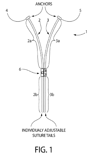
[000092] Figure 1 is a plan view of a dual-strand suture article 1 having
sutures 2
and 3 with respective barbs 4 and 5, and a suture lock or cinching fixture 6.
The
sutures 2 and 3 are independently adjustable through the suture lock or
cinching fixture
6, so as to be able to take up any slack suture material between the suture
lock or
22
CA 03043526 2019-05-09
WO 2018/089838 PCT/US2017/061164
cinching fixture 6 and respective barbs 4 and 5. The suture article 1 is
adapted to be
inserted into opposing tissue surfaces at two respective locations and to draw
the tissue
surfaces toward one another, the suture article comprising: (a) two lengths of
suture
material (whether monofilament or thread) 2 and 3, each length having a
terminal end
(2a and 3a, respectively) having a barb 4 and 5 adapted to resist withdrawal
from
respective opposing tissue surfaces. The suture material lengths have an
opposite end
(2b and 3b, respectively), and these lengths are arranged alongside one
another such
that the terminal ends are collateral with respect to the cinching fixture 6.
The cinching
fixture 6 is adapted to slidingly engage the lengths of suture material 2 and
3 so as to be
able to move from the opposite ends toward the terminal ends, so as to move
the barbs
4 and 5 from a relatively more distant position to a relatively near position
with respect
to one another, and so as to maintain the barbs 4 and 5 in the relatively
closer position
to bring about and maintain the tissue approximation.
[000093] Figure 2a is a perspective view of a suture lock or cinching
fixture 6,
defining suture channels 7 and 8 which define a suture material path for the
suture
materials 2 and 3. The suture lock or cinching fixture 6 in this variation
features a series
of extensions 9 opposed to respective openings 9a in channel 7 and
extensions10
opposed to respective openings 10a in channel 8 that form a non-linear path
for the
suture material path to bring about sufficient frictional force to resist
movement from a
set position, but which can be overcome by hand force as the suture lock or
cinching
fixture 6 is advanced toward the barbed end of the sutures.
[000094] Figure 2b is an end elevation view of a suture lock or cinching
fixture 6
also showing suture channels 7 and 8 (of a nominal suture diameter) (i.e., in
a vertical
23
CA 03043526 2019-05-09
WO 2018/089838 PCT/US2017/061164
arrangement) and the series of extensions 9 and extensions10 extending into
suture
channels 7 and 8.
[000095] Figure 2c is a plan view of a suture lock or cinching fixture 6
also showing
suture channels 7 and 8 showing the nominal suture diameter (d), and the
juxtaposition
of series of extensions 9 opposed to respective openings 9a in channel 7 and
extensions10 opposed to respective openings 10a in channel 8.
[000096] Figure 2d is a lateral sectioned view, taken along line A-A of
Figure 2c, of
a suture lock or cinching fixture 6 showing suture channel 7, and showing the
nominal
suture diameter (d) as well as the juxtaposition of a series of extensions 9
opposed to
respective openings 9a in channel 7.
[000097] Figure 3a is a detailed, partially sectioned perspective view of a
dual-
strand suture article 1, showing the lengths of suture material 2 and 3
extending through
suture channels 7 and 8 respectively (i.e., shown and described in Figure 2a)
and being
held in position by suture lock or cinching fixture 6 by action of extensions
9 opposed to
respective openings 9a in channel 7 and extensions10 (see Figure 2b) opposed
to
respective openings 10a in channel 8.
[000098] Figure 3b shows a detailed perspective view of a dual-strand
suture article
1 wherein like numerals refer to the aforementioned parts or aspects thereof.
[000099] As may be appreciated from Figure 1, suture materials 2 and 3 may
be
combined as a single suture forming a V-shape with two sub-lengths equivalent
to the
lengths of suture materials 2 and 3 and joined at an intersection on the non-
barbed side
of the suture lock or cinching fixture 6 (i.e., by joining opposite ends 2b
and 3b), and this
variant may be created from any of the dual-length suture material embodiments
24
CA 03043526 2019-05-09
WO 2018/089838 PCT/US2017/061164
described herein. These angled or V-shaped variants may be produced by forming
the
suture material of such type and thickness that the single suture holds its V-
shape when
at rest.
[0000100] Figures 4a ¨ 5b show an alternative variant of the present
invention that
may be used in accordance with the arrangement shown in Figure 1.
[0000101] Figure 4a is a perspective view of a suture lock or cinching
fixture 16,
defining suture channels 17 and 18 which define a suture material path for the
suture
materials 2 and 3 (i.e., replacing suture lock or cinching fixture 6 shown in
Figure 1).
The suture lock or cinching fixture 16 in this variation features a series of
relatively
flexible extensions 19 opposite regions of reduced diameter (i.e., less than
the nominal
diameter of the suture material) formed by protrusions 19a in channel 17 and
relatively
flexible extensions 20 opposite regions of reduced diameter formed by
protrusions 20a
in channel 18 that form a linear path for the suture material path. The
flexible
extensions and reduced diameter protrusions 19a and 20a bring about sufficient
frictional force to resist movement of the suture material from a set
position, but which
can be overcome by hand force as the suture lock or cinching fixture 16 is
advanced
toward the barbed end of the sutures.
[0000102] Figure 4b is an end elevation view of a suture lock or cinching
fixture 16
also showing suture channels 17 and 18 (of a nominal suture diameter (d))
(i.e., in a
horizontal arrangement) and the series of relatively flexible extensions 19
and
protrusions 19a, and relatively flexible extensions 20 and protrusions 20a,
extending
respectively into suture channels 17 and 18.
CA 03043526 2019-05-09
WO 2018/089838 PCT/US2017/061164
[0000103] Figure 4c is a lateral sectioned view, taken along line A-A of
Figure 4b, of
the suture lock or cinching fixture 16, and showing the relative position of
relatively
flexible extensions 20 and protrusions 20a.
[0000104] Figure 5a is a detailed, partially sectioned perspective view of
a dual-
strand suture article 21, showing the lengths of suture material 22 and 23
extending
through suture channels 17 and 18 respectively (see Figure 4a), and being held
in
position by suture lock or cinching fixture 16 respectively by action of
relatively flexible
extensions 19 and protrusions 19a, and relatively flexible extensions 20 and
protrusions
20a.
[0000105] Figure 5b shows a detailed perspective view of a dual-strand
suture article
21 wherein like numerals refer to the aforementioned parts or aspects thereof.
[0000106] Figures 6a ¨ 7b show an alternative variant of the present
invention that
may be used in accordance with the arrangement shown in Figure 1.
[0000107] Figure 6a is a perspective view of a suture lock or cinching
fixture 31,
defining suture channels 32 and 33 which define a suture material path for the
suture
materials 37 and 38 (see Figures 7a and 7b) (i.e., replacing suture lock or
cinching
fixture 6 shown in Figure 1). The suture lock or cinching fixture 31 in this
variation
features single relatively flexible extensions 34 and 35 respectively
extending into
suture channels 32 and 33 so as to form a reduced diameter suture material
path. The
relatively flexible extensions 34 and 35 bring to bear sufficient frictional
force to resist
movement of the suture material from a set position, but which can be overcome
by
hand force as the suture lock or cinching fixture 31 is advanced toward the
barbed end
of the sutures.
26
CA 03043526 2019-05-09
WO 2018/089838 PCT/US2017/061164
[0000108] Figure 6b shows an elevation view of a suture lock or cinching
fixture 31
wherein like numerals refer to the aforementioned parts or aspects thereof.
Figure 6b
also shows the nominal suture diameter (d).
[0000109] Figure 6c is a lateral sectioned view of a suture lock or
cinching fixture 31,
taken along line A-A of Figure 6b, wherein like numerals refer to the
aforementioned
parts or aspects thereof. Figure 6c also shows the relative size of the
nominal suture
diameter (d), it being understood that the nominal suture diameter, opening
size and
extension flexibility may be varied to adjust performance of the suture lock
or cinching
fixture in terms of the amount of hand force needed to overcome the imposed
friction,
strength of locking force, etc.
[0000110] Figure 7a is a detailed, partially sectioned perspective view of
a dual-
strand suture article 36, showing the lengths of suture material 37 and 38
extending
through suture channels 32 and 33 respectively, and being held in position by
suture
lock or cinching fixture 31 respectively by action of relatively flexible
extensions 34 and
35.
[0000111] Figure 7b shows a detailed perspective view of a dual-strand
suture article
36 wherein like numerals refer to the aforementioned parts or aspects thereof.
[0000112] Figures 8 ¨ 10b shows several additional suture article and
suture lock or
cinching fixture variants that may be applied in the dual-strand, angled or V-
shaped
suture articles of the present invention.
[0000113] Figure 8 is a detailed, partially sectioned perspective view of a
dual-strand
suture article 39 having a suture lock or cinching fixture 40 that captures
both suture
materials 42 and 43 in a single channel (i.e., replacing suture lock or
cinching fixture 6
27
CA 03043526 2019-05-09
WO 2018/089838 PCT/US2017/061164
shown in Figure 1). This variant features internal barbs 41 extending into the
channel
so as to provide a one-way zip-lock to the suture materials 42 and 43, as the
suture lock
or cinching fixture 40 is advanced toward the barbed ends of the sutures.
[0000114] Figures 9a and 9b are detailed, partially sectioned perspective
views of a
locking progression of a single-strand suture article/cinching feature
combination 44
having a suture lock or cinching fixture 45 including a collet 46 that
features a toothed,
barbed or otherwise gripping internal surface, and is shaped so as to be able
to grip the
suture material and then be drawn into the suture channel so as to provide an
interference lock against the suture material 47, as shown in the progression
from
Figures 9a to 9b. This allows suture material 47 to be drawn though the suture
lock or
cinching fixture 45 as shown in Figure 9a and then to be engaged by collet 46
when
withdrawn in the opposite direction as shown Figure 9b such that the collet 46
and the
inner channel surface of suture lock or cinching fixture 45 cooperate to lock
the suture
material in place. This variant may be adapted to a dual-strand variant by
forming two
side-by-side suture lock or cinching fixtures 45 to provide for the cinching
and locking of
two individual suture strands.
[0000115] Figures 10a and 10b are detailed, partially sectioned perspective
views of
a locking progression of a dual-strand suture article 48 comprising two suture
material
strands 51 and 52, and a suture lock or cinching fixture 49 having a flexible,
toothed (or
otherwise gripping) opposed claw portions 50 that feature a toothed, barbed or
otherwise gripping internal surface, the opposed claw portions 50 being shaped
so as to
be able to grip the suture material and be drawn into the suture channel so as
to provide
an interference lock against the suture material strands 51 and 52, as shown
in the
28
CA 03043526 2019-05-09
WO 2018/089838 PCT/US2017/061164
progression from Figure 10b to 10a. This allows suture material strands 51 and
52 to
be drawn though the suture lock or cinching fixture 49 as shown in Figure 10b
and then
to be engaged by opposed claw portions 50 when withdrawn in the opposite
direction as
shown Figure 10a such that the opposed claw portions 50 cooperate to lock the
suture
material strands 51 and 52 in place.
[0000116] Figure 11a is a detailed, partially sectioned perspective view of
a dual-
strand suture article 53 comprising two suture material strands 56 and 57, and
a suture
lock or cinching fixture 54 having a flexible, toothed (or otherwise gripping)
claw portions
50 that feature a toothed, barbed or otherwise gripping internal surface,
which portions
govern lateral channels 58, the opposed claw portions 50 being shaped so as to
be able
to grip the suture material and be drawn through the lateral suture channels
58 so as to
provide an interference lock against the suture material strands 56 and 57, as
shown in
the progression from Figure llb to 11a. This allows suture material strands 56
and 57
to be drawn though the suture lock or cinching fixture 54 as shown in Figure
11a and
then to be engaged by opposed claw portions 55 when withdrawn in the opposite
direction as shown Figure llb such that the opposed claw portions 55 cooperate
to lock
the suture material strands 56 and 57 in place.
[0000117] It will be appreciated that the suture lock or cinching fixture
may be
produced in variations adapted to accommodate more than two strands of suture
material by forming multiple side-by-side suture lock or cinching fixtures of
the type
described herein (such as suture lock or cinching fixtures comprising 3, 4 or
5+
individual suture material lengths), and this may be done through the same
molding
processes by which the above-described variants may be produced. Such variants
29
CA 03043526 2019-05-09
WO 2018/089838 PCT/US2017/061164
permit the independent tensioning and/or cinching or locking of two or more
lengths of
suture material. This permits the user to independently tension each suture
length and
thereby bring to bear differing amounts of approximating force to each tissue
attached
thereto.
[0000118] The suture lock or cinching fixture may be produced from known
polymeric
materials such as known bioresorbable polymers known and used in the art. The
most
common bioresorbable polymer is polylactic acid (PLA), also known as
polylactide, and
is made from a lactide monomer. Generally speaking, PLA is the main building
block for
bioresorbable polymer materials. Common derivatives of PLA are poly-L-lactide
(PLLA),
poly-D-Iactide (PDLA) and poly-DL-lactide (PDLLA). When in the body, PLA
degrades
into lactic acid, a non-toxic chemical which occurs naturally in the body.
Polyglycolic
acid (PGA), or polyglycolide (PG), is another type of bioresorbable polymer
usually used
for bioresorbable sutures. The material may be copolymerised with lactic acid
to form
poly(lactic-co-glycolic acid), or PLGA, with e-caprolactone to form
poly(glycolide-co-
caprolactone), or PGCL, and with trimethylene carbonate to form poly(glycolide-
co-
trimethylene carbonate), or (PGA-co-TMC). PGA degrades to form glycolic acid.
[0000119] The sutures that may be used in accordance with the present
invention
may have conventional monofilament or multifilament constructions. Examples of
absorbable suture materials include absorbable polyester polymers and
copolymers
such as lactides, glycolides, polydioxanone, epsilon-caprolactone, polylactic
acid,
polyglycolic acid, and copolymers and blends thereof and equivalents thereof
and the
like, and may include conventional materials such as cat gut. Examples of
nonabsorbable polymers include polyesters, silk, polyolefins such as
polypropylene and
CA 03043526 2019-05-09
WO 2018/089838 PCT/US2017/061164
polyethylene, nylon, and the like. Commercially available sutures that may be
used with
the stay suture devices of the present invention include the following sutures
manufactured and sold by Ethicon, Inc., Somerville, N.J. 08876, USA such as
Coated
VICRYL Plus Suture, Coated VICRYL Suture, MONOCRYL Plus Suture, MONOCRYL
Suture, PDS Plus Suture, PDS Suture, Surgical Gut Suture--Chromic, Surgical
Gut
Suture--Plain, PRONOVA Suture, ETHIBOND EXCEL Suture, ETHILON Suture,
MERSILENE Suture, NUROLON Suture, PERMA-HAND Silk Suture, PROLENE
Suture, and the like. The sutures will have a size that is effective to secure
the tissue to
be approximated in place, and the selection will be within the discretion of
the surgeon.
Although any size sutures may be used, typically the size of the sutures will
range from
a size of 2 to 6-0.
[0000120] Figure 12 is a perspective view of a suture placement device 60
in
accordance with one embodiment of the present invention. The suture placement
device 60 comprises a handle portion 61 having an insertion-directed end, an
insertion
portion 62 extending from the insertion-directed end of the handle portion 61
and
comprising a proximal end 62b and a distal end 62a, the distal end 62a
comprising
barb-directing portions 63a and 63b that diverge from one another so as to
form a V-
shape, the distal ends of the barb-directing portions being hollow to
releasably hold
barbs 64, as can be appreciated more clearly in Figures 14 and 15. This
embodiment
of the suture placement device features two angled "needles" that support two
barb-
tipped sutures (whether single suture or independent lengths). The two barb-
tipped
sutures where comprising independent lengths (such as 66a and 66b) are fed
down the
31
CA 03043526 2019-05-09
WO 2018/089838 PCT/US2017/061164
hollow cinching cannula/suture conduit 65 (see Figure 13) that extends through
a
channel in the handle portion 61 and is slidingly engaged therein.
[0000121] Figure 13 is a partially sectioned perspective view of a suture
placement
device 60 in accordance with one embodiment of the present invention. This
Figure
shows the hollow cinching cannula/suture conduit 65 having a distal end 65a
and
slidingly engaged by the handle portion 61 so as to be moveable between
positions
wherein the distal end 65a is relatively nearer the handle 61 and wherein the
distal end
65a is relatively nearer the insertion portion's distal end 62a. The hollow
cinching
cannula/suture conduit 65 is slidingly contained within outer cannula 69, and
is adapted
to maintain a suture material 66 (i.e., comprising respective lengths 66a and
66b)
extending from the insertion portion proximal end 65b to the insertion portion
distal end
65a, and a control knob 67 that extends through the handle portion 61. The
control
knob in this embodiment may be guided in its movement by control slot 68.
[0000122] Figures 12 and 13 thus show the suture placement device 60
featuring
two angled barbed ends, the angle of the barbed ends may be at any angle,
acute or
obtuse, depending upon the desired application, though acute angles typically
will be in
the range of from about 20 to about 45 degrees in the displayed embodiment.
[0000123] The suture material 66 may be in the form of a dual-strand suture
(as
shown in the Figures or an angled (e.g., V-shaped) suture in which case the
angled
(e.g., V-shaped) suture is deployed by the device with the aid of a secondary
suture that
is looped through the angled suture intersection (and proximally of the suture
lock or
cinching fixture). The angled suture provides a multi-anchored suture article
comprising
a length of suture material having barbs on its terminal ends and comprising
two sub-
32
CA 03043526 2019-05-09
WO 2018/089838 PCT/US2017/061164
lengths maintained at an angle to one another so as to form an intersection,
each distal
end of the anchor-directing portion being releaseably engaged to respective
anchors, in
this case barbs at the terminal ends of suture material.
[0000124] Figures 14 and 15 show suture placement device 60 in the loaded
condition holding barb-tipped sutures having respective barbs 64a and 64b.
[0000125] Figure 14 is a detailed perspective view of the insertion portion
62a of a
suture placement device 60 and Figure 15 is a detailed, partially sectioned
perspective
view thereof. Figures 14 and 15 show a suture lock or cinching fixture 70
which may be
any of those shown and described herein (e.g., such as suture lock or cinching
fixture 6,
16, 31, 39, 44, 48 and 53). The Figures 14 and 15 show in greater detail how
the suture
lock or cinching fixture 70 is adapted to slidingly engage the suture lengths
66a and 66b
and to be moved distally so as to shorten the portions of suture lengths 66a
and 66b
between the suture lock or cinching fixture 70 and the respective barbs 64a
and 64b,
once the barbs 64a and 64b have been placed in the tissue for approximation.
As may
be appreciated from Figures 14 and 15, the suture placement device 60 is
loaded with
the barb-tipped sutures 66a and 66b (the distal portions thereof optionally
seated in
respective slots in angled barb-directing portions 63a and 63b). Barbs 64a and
64b are
releasably engaged respectively with barb-directing portions 63a and 63b such
that the
barbs may be urged into place in the tissue to be approximated, and released
upon
withdrawal of the device, as described in the later Figures herein.
[0000126] The suture lock or cinching fixture 70 is urged distally by the
hollow
cinching cannula/suture conduit 65 by being slidingly engaged by the handle
portion 61
(and its outer cannula 69) so as to be moveable along axis A between a
position
33
CA 03043526 2019-05-09
WO 2018/089838 PCT/US2017/061164
wherein the hollow cinching cannula/suture conduit distal end 65a is
relatively nearer
the handle 61, and a position wherein the hollow cinching cannula/suture
conduit distal
end 65a is relatively nearer the insertion portion distal end 62a, the hollow
cinching
cannula/suture conduit 65 adapted to maintain a suture material extending from
the
insertion portion proximal end 65b to the insertion portion distal end (i.e.,
opposite 65a).
The inner diameter of the hollow cinching cannula/suture conduit 65 will be
sized so as
to be adapted to releasably capture the suture lock or cinching fixture 70 and
urge
distally to be able to cinch the suture portions and thereby approximate the
tissue
pieced by the barbs 64a and 64b.
[0000127] Figures 14 and 15 also show that barb-directing portions 63a and
63b may
be hollow on their distal ends to accept barbs 64a and 64b to be releasably
engaged
respectively thereby and a portion of barb-directing portions 63a and 63b may
further be
grooved proximally to accommodate respectively the distal ends of suture
lengths 66a
and 66b.
[0000128] In similar fashion, where an angled, V-shaped dual barbed suture
is used
(i.e. where, instead of using two suture lengths 66a and 66b, these lengths
are
combined as an angled single suture by forming an intersection on the non-
barbed (i.e.,
proximal) side of the suture lock or cinching fixture 70, forming sub-lengths
of an angled
(or V-shaped) single suture and bearing the suture lock or cinching fixture
70), an
additional suture material may be threaded through the loop formed at the
intersection
to permit the additional suture material to provide a counterforce as the
suture lock or
cinching fixture 70 is urged forward (i.e., the two ends thereof extending in
the same
fashion as the proximal ends of suture lengths 66a and 66b extend from the
hollow
34
CA 03043526 2019-05-09
WO 2018/089838 PCT/US2017/061164
cinching cannula/suture conduit 65 in Figures 12 and 13), so as to be able to
move the
suture lock or cinching fixture 70 from the intersection toward the barbs 64a
and 64b, so
as to move barbs 64a and 64b from a relatively distant position to a
relatively near
position with respect to one another, and so as to maintain the barbs in the
relatively
closer position to effect tissue approximation.
[0000129] At least a portion of the suture lock or cinching fixture 70
typically will be
greater in width than the distal end 65a of the hollow cinching cannula/suture
conduit 65
(such as containing a taper or the like), so as to be able to transmit urging
force.
[0000130] Figures 16 ¨ 28 show a stepwise progression of the use of the
suture
placement device 60, and represent an example of the method of tissue
approximation
brought about by its use.
[0000131] Figure 16 is an isometric perspective view of the suture
placement device
60, shown in an approach to a representation of tissue to be joined, i.e.,
upper and
lower tissue portions 71 and 72 having respective opposing surfaces 73 and 74.
Figure
16 shows the suture placement device 60 having barb-directing portions 63a and
63b
being loaded with the barbs 64a and 64b as shown and described in Figures 12 ¨
14,
and with the hollow cinching cannula/suture conduit 65 (see Figure 17)
retracted to the
rear position as indicated by the position of control knob 67. Barbs 64a and
64b are
directed in their approach, respectively, to tissue surfaces 73 and 74.
[0000132] It will be appreciated that the user may to an extent control the
position
and depth of the insertion of the respective anchors by moving the handle with
respect
to axis A, and through the rotation thereof about axis A. The depth of the
insertion may
to an extent be controlled through differential advancement of the suture
placement
CA 03043526 2019-05-09
WO 2018/089838 PCT/US2017/061164
device so as to advance one of the anchors more or less into the respective
tissue
surface. This extent of insertion into the space between the tissue surfaces
and the
depth of insertion will be within the control of the user and will depend upon
the type of
operation and the desired clinical outcome.
[0000133] Figure 17 is an isometric lateral view of the suture placement
device 60,
showing a lateral view of an approach to a representation of tissue to be
joined, and
ready for insertion.
[0000134] Figure 18 is an isometric view of the suture placement device 60,
showing
the insertion of barbs 64a and 64b by barb-directing portions 63a and 63b (see
Figure
12) into the tissue surfaces 73 and 74 requiring approximation (such as on
either side of
an incision, or the like).
[0000135] Figure 19 is a detailed isometric lateral view of the insertion
portion's barb-
directing portions 63a and 63b of the suture placement device 60 as they guide
insertion of barbs 64a and 64b into tissue surfaces 73 and 74.
[0000136] Figure 20 is an isometric view of the suture placement device 60,
showing
the barb-directing portions 63a and 63b directing barbed sutures having barbs
64a and
64b into a representation of tissue surfaces 73 and 74 to be approximated, and
showing
the suture placement device 60 withdrawn substantially along axis A to release
barbs
64a and 64b from barb-directing portions 63a and 63b. In this view, the suture
placement device 60 is withdrawn leaving the barb-tipped sutures 66a/64a and
66b/64b
in the respective tissue surfaces73 and 74.
[0000137] Figure 21 is a detailed isometric lateral view of the barb-
directing portions
63a and 63b of a suture placement device 60 having released barbs 64a and 64b
and
36
CA 03043526 2019-05-09
WO 2018/089838 PCT/US2017/061164
being withdrawn substantially along axis A following insertion thereof into a
representation of tissue surfaces 73 and 74.
[0000138] Figure 22 is an isometric view of the suture placement device 60,
shown
being rotated about 90 degrees with respect to the plane containing the
inserted barbs
64a and 64b (as indicated by the position of control knob 67) and with the
hollow
cinching cannula/suture conduit 65 still retracted to the rear position as
indicated by the
position of control knob 67, to best allow the tissue surfaces 73 and 74 to
approximate.
[0000139] Figure 23 is an isometric view of the suture placement device 60,
shown
being rotated about 90 degrees with respect to the plane containing the
inserted barbs
64a and 64b (see Figures 20 and 21), and with the hollow cinching
cannula/suture
conduit 65 advanced to the forward position to urge suture lock or cinching
fixture 70
(see Figure 21) distally so as to draw inserted barbs 64a and 64b toward one
another
and thereby approximate tissue surfaces 73 and 74 with the hollow cinching
cannula/suture conduit 65 being extended from within outer cannula 69. In this
way the
barb-directing portions 63a and 63b of a suture placement device 60 do not
interfere
with the intended approximation of the tissue surfaces 73 and 74. The cinching
cannula/suture conduit 65 may then be extended by manual action (such as
through the
use of control knob 67 or direct action upon the proximal end (i.e., opposite
distal end
65a) of the hollow cannula/suture conduit 65b). Manual counterforce may also
be
applied directly to the proximal ends of barb-tipped suture lengths 66a and
66b. Thus,
by holding the suture placement device 60 and the proximal ends of barb-tipped
suture
lengths 66a and 66b, the user can tension the distal ends of suture lengths
66a and
37
CA 03043526 2019-05-09
WO 2018/089838 PCT/US2017/061164
66b, drawing inserted barbs 64a and 64b toward one another and fixing them in
place
through cinching the suture lengths by action of cinching fixture 70.
[0000140] Figure 24 is a detailed isometric view of the inserted barbs 64a
and 64b
into a representation of tissue 71 and 72 to be joined and with the cinching
hollow
cannula/suture conduit 65 being extended to urge suture lock or cinching
fixture 70
distally so as to draw inserted barbs 64a and 64b toward one another and
thereby
approximate tissue surfaces 73 and 74 substantially along lines B and C, with
the
hollow cinching cannula/suture conduit 65 being extended from within outer
cannula 69.
[0000141] Figure 25 is an isometric lateral view of the withdrawn suture
placement
device 60 following approximation of tissue surfaces 73 and 74 (see Figure
24), and
showing the extended suture material 66a and 66b.
[0000142] In another variant, where a single suture (such as an angled, V-
shaped
suture or other multi-dentate suture forming an intersection of constituent
anchor-
bearing lengths is used) the distal portions of suture lengths 66a and 66b
(and barbs
64a and 64b) are essentially replaced by a separate suture length that extends
through
the hollow cinching cannula/suture conduit 65 and loops around the angled
suture (or
other multi-dentate suture) intersection to permit the user to exert
counterforce as the
hollow cinching cannula/suture conduit 65 is urged forward against suture lock
or
cinching fixture 70 as described herein.
[0000143] Figure 26 is a detailed isometric lateral view of hollow cinching
cannula/suture conduit 65 being extended from within outer cannula 69 and
shown
following closure of the represented tissue surfaces 73 and 74 (see Figure
24)by the
barbed suture held by inserted barbs 64a and 64b.
38
CA 03043526 2019-05-09
WO 2018/089838 PCT/US2017/061164
[0000144] Figure 27 is an isometric lateral view of the closure of the
represented
tissue by the barbed suture, following withdrawal of the suture placement
device 60
along axis A. The user thus may release the proximal ends of suture material
66a and
66b, withdraw the suture placement device from around the suture material, and
allow
the suture material to be trimmed as desired.
[0000145] Figure 28 is a detailed isometric lateral view of the closure of
the
represented tissue surfaces 73 and 74 (see Figure 24)by the barbed suture,
following
withdrawal of the suture placement device 60, leaving extended suture material
66a and
66b.
[0000146] Figure 29 is a photographic perspective view of a suture
placement device
60 in accordance with one embodiment of the present invention with the hollow
cinching
cannula/suture conduit 65 being retracted.
[0000147] Figure 30 is a photographic perspective view of a suture
placement device
in accordance with one embodiment of the present invention with the hollow
cinching
cannula/suture conduit 65 being extended.
[0000148] Figure 31 is a detailed photographic perspective view of the barb-
directing
portions 63a and 63b of a suture placement device 60 in accordance with one
embodiment of the present invention with the hollow cinching cannula/suture
conduit 65
being retracted.
[0000149] The foregoing is but one embodiment of the invention.
[0000150] It will be appreciated that other variations using more than two
anchor-
insertion arms, such as a tri-dentate quadra-dentate variations, for
application where it
is desired to place multiple anchors simultaneously. Such devices may be
constructed
39
CA 03043526 2019-05-09
WO 2018/089838 PCT/US2017/061164
by adding additional anchor-directing portions (such as 63a and 63b) about the
path of
the hollow cinching cannula/suture conduit, and such additional anchor-
directing
portions may be of the same or varied lengths and at any angle to one another
so as to
orient the anchor-directing portions spatially depending upon the desired
application by
presenting the anchor-directing portions at any orientation in space.
[0000151] In such multi-dentate devices, it will be understood that the
anchor
insertion portion typically will be fully withdrawn from the approximation
area to
eliminate any interference with the approximation by the structure of the
multi-dentate
distal end, as such multi-dentate distal ends may not as easily be rotated out
of the way
to permit approximation of facing tissues, as is possible in the case of the
angled (such
as multi-V-shaped) device.
[0000152] It will also be appreciated that the devices may be varied with
respect to
the lengths of the constituent anchor-insertion arms, and/or the angles of the
anchor-
insertion arms with respect to one another, such that the spatial array of the
anchor-
insertion points may be tailored to specific tissues, tissue types or tissue
surfaces
and/or tissue presentments requiring approximation, or differing tissue
approximation
environments, such as those presented in mastectomies or in tumor resection.
[0000153] Other variations and embodiments of the invention include those
devices
and methods that may be adapted for laparoscopic surgery or other types of
minimally
invasive surgery. Such device variants include those wherein the above-
described
handle portion may be eliminated in favor of using a simple hand-actuated
hollow
cinching cannula/suture conduit so as to reduce the width of the device to
best
accommodate laparoscopic surgery or keyhole surgery. In this embodiment, the
hollow
CA 03043526 2019-05-09
WO 2018/089838 PCT/US2017/061164
cinching cannula/suture conduit may be thumb actuated by the user, or may be
fitted
with a thumb wheel to allow the user to advance the hollow cinching
cannula/suture
conduit with respect to the anchor-directing portions, to cinch the suture
lengths while
counterforce is exerted and maintained, as otherwise described herein for
manual
operation involving use of the handle portion.
[0000154] In similar fashion, other variations and embodiments of the
invention
include those devices and methods that may be adapted for robotic surgery. In
this
variant, the handle portion may be eliminated in favor of a fitment to affix
the device to a
robotic arm that permits the anchor-directing portions, such as barb-directing
portions
63a and 63b, robotically to be advanced (and where required rotated) and the
hollow
cinching cannula/suture conduit robotically to be actuated to cinch the suture
lengths
while counterforce is exerted and maintained, as described herein for manual
operation.
[0000155] While particular embodiments of the present invention have been
illustrated and described, it would be obvious to those skilled in the art
that various other
changes and modifications can be made without departing from the spirit and
scope of
the invention. It is therefore intended to cover in the appended claims all
such changes
and modifications that are within the scope of this invention.
41