Note: Descriptions are shown in the official language in which they were submitted.
CA 03043539 2019-05-10
WO 2018/093387 PCT/US2016/063021
TITLE
AUTOMATIC PARKING BRAKE FOR BODY MOUNTED BRAKE CYLINDER
BACKGROUND OF THE INVENTION
1. FIELD OF THE INVENTION
[0001] The present invention relates to rail car braking systems and,
more
particularly, to an automatic parking brake that may be used with body mounted
brake
cylinders.
2. DESCRIPTION OF THE RELATED ART
[0002] Most rail vehicles have a manually-operated parking brake that
applies the
wheel brakes. Unfortunately, this requires that an operator manually apply the
brake on each
rail car in a train. As a result, an automatic parking brake, such as that
disclosed in U.S.
Patent No. 7,163,090, has been developed that will retain the braking system
of any rail car
equipped with the brake in the brakes applied position if brake pipe pressure
is removed from
a locking mechanism position about the shaft of the brake cylinder. Body mount
brake
cylinders are typically constructed with a hollow rod affixed to the piston
and apply the brake
force to the brake rigging by means of a push rod inside the hollow rod. This
arrangement
accommodates angular misalignment of the push rod as the connected brake lever
operates
through an arc, and decouples the manual hand brake from the body mount
cylinder when the
cylinder is released and the hand brake applies. In the hand brake applied
position, the
rigging pulls the body mount brake push rod independent of the brake piston,
allowing the
brake piston to remain in the released position, and decouples the influence
of the body
mount brake cylinder return spring from the hand brake application. While
automatic
parking brake systems that allow bot push rod angular movement and decoupling
have
recently been incorporated into body mount brake cylinders, manual release of
the automatic
parking brake may be problematic if the manual release is not held long enough
or if there is
still pressure in the brake cylinder. Accordingly, there is a need for an
automatic parking
brake for a body mount brake cylinder with an improved manual release.
BRIEF SUMMARY OF THE INVENTION
[0003] The present invention is an automatic parking brake system for a
body mount
brake cylinder that ensures proper release of the brakes when the manual
release is used. The
brake cylinder has a main piston that is moveable along an longitudinal axis
in response to
pneumatic pressure supplied to a chamber behind piston by a source of brake
cylinder
pressure, a spring biasing piston into a brakes released position when
pressure in the chamber
is released, and a shaft having a hollow cavity that coupled to the main
piston and moveable
1
CA 03043539 2019-05-10
WO 2018/093387 PCT/US2016/063021
therewith to cause a piston rob therein to apply and release the brakes of a
rail car. The
locking mechanism comprises a tube surrounding the shaft that coupled to the
main piston
and has a first set of teeth formed along an outer surface thereof. A gate
having a second set
of teeth corresponding to the first set of teeth is moveable in a slot that
extends along a
transverse axis to the longitudinal axis of the brake cylinder between a first
position wherein
the first and second set of teeth are engaged to prevent movement of the main
piston and a
second position where the first and second set of teeth are disengaged to
allow movement of
the main piston. A spring biases the gate into the first position and a
parking brake piston
that is responsive to a source of brake pipe pressure is interconnected to the
gate to move the
gate into the second position so that the main piston is free to move. The
piston is
interconnected to the gate by a lever that rotates a cam to impart a force to
a roller that
engages the gate to move it into the second position against the bias of the
spring.
BRIEF DESCRIPTION OF THE SEVERAL VIEWS OF THE DRAWING(S)
[0004] The present invention will be more fully understood and
appreciated by
reading the following Detailed Description in conjunction with the
accompanying drawings,
in which:
[0005] FIG. 1 is a longitudinal cross-section with inset of an automatic
parking brake
system according to the present invention;
[0006] FIG. 2 is a partial cross-section of an automatic parking brake
system
according to the present invention; and
[0007] FIG. 3 is a partial cross-section of a automatic releasing
mechanism for
automatic parking brake system from a first perspective according to the
present invention;
and
[0008] FIG. 4 is a partial cross-section of an automatic releasing
mechanism for an
automatic parking brake system from a second perspective according to the
present invention;
[0009] FIG. 5 is a partial cross-section of a manual releasing mechanism
for an
automatic parking brake system from a second perspective according to the
present invention;
[0010] FIG. 6 is a partial cross-section of a manual releasing mechanism
for an
automatic parking brake system from a second perspective according to the
present invention;
[0011] FIG. 7 is a perspective view of interconnected manual releasing
mechanisms
for an automatic parking brake system from a second perspective according to
the present
invention;
[0012] FIG. 8 is partial cross-section of a visual indicator for an
automatic parking
brake system in a withdrawn position; and
2
CA 03043539 2019-05-10
WO 2018/093387 PCT/US2016/063021
[0013] FIG. 9 is partial cross-section of a visual indicator for an
automatic parking
brake system in an extended position.
DETAILED DESCRIPTION OF THE INVENTION
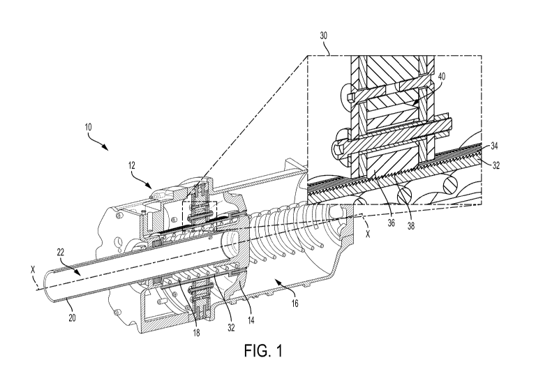
[0014] Referring to the figures, wherein like numerals refer to like
parts throughout,
there is seen in FIG. 1 a body mounted brake cylinder 10 having an automatic
parking brake
12 associated therewith. Brake cylinder 10 includes a piston 14 that moves in
response to
pneumatic pressure supplied to a chamber 16 behind piston 14 by a source of
brake cylinder
pressure. A spring 18 biases piston 14 into a brakes released position when
pressure in
chamber 16 is released. A shaft 20 having a hollow cavity 22 is coupled to
piston 14 and
moveable therewith. Hollow cavity 22 of shaft 20 is dimensioned to enclose a
piston rod that
is seated against piston 14 at one end and is coupled to the braking system at
its other end to
apply and release the brakes of a rail car when piston 14 is moved
accordingly. As a result,
the piston rod is free to pivot relative to piston 14 within the bounds of
shaft 22 to
accommodate angular misalignment of the piston rod as the brake lever of the
braking system
to which the piston rod in connected operates through an arc and to physically
separate from
piston 14 if the brake lever moves farther than piston 14 is capable of
traveling.
[0015] Automatic parking brake 12 comprises a locking mechanism 30 having
a tube
32 with teeth 34 formed along its surface. Tube 32 is fixed to piston 14 and
positioned
around hollow shaft 20. Locking mechanism 30 also include a gate 36 having
teeth 38
corresponding to teeth 34 of tube 32. Gate 36 is positioned in a slot 40 that
extends
transversely relative to tube 32 and the longitudinal axis X-X of brake
cylinder 10 along
which piston 14 translates. Gate 36 is moveable within slot 40 so that teeth
38 may be moved
into and out of engagement with corresponding teeth 34 of tube 32. Referring
to FIG. 2, a
spring 42 is positioned in slot 40 to bias gate 36 into the interlocked
position with tube 32,
thereby preventing any movement of piston 14 to accomplish the function of a
parking brake.
An additional locking mechanism 30 may be provided on an opposing side of
brake cylinder
to equalize the forces across piston 14 and hollow rod 32 when the braking
system is
under tension, such as when the parking brake is set.
[0016] Referring to FIG. 3, automatic parking brake 12 further comprises
an actuating
assembly 50 having a piston 52 biased in one direction by a return spring 54
and in a second,
opposite direction by a source of brake pipe pressure applied coupled to a
brake pipe pressure
port 56. Piston 52 is interconnected via a shaft 58 to the lever 60 of a cam
assembly 62. Cam
assembly 62 comprises a central cam 64 that can be rotated into and out of
engagement with
both of a pair of opposing rollers 66 (one roller 66 for each gate 32 used
according to the
3
CA 03043539 2019-05-10
WO 2018/093387 PCT/US2016/063021
present invention). Referring to FIG. 4, each roller 66 can engage a flange 44
coupled to a
corresponding gate 36 so that gates 36 will move when cam 64 engages rollers
66 and moves
rollers 66 into flanges 44. Lever 60 of cam assembly 62 is moveable to cause
cam 64 to
rotate into and out of engagement each roller 66 of each gate 36, thereby
selectively locking
or unlocking gates 36 from tube 32. Movement of piston 52 in response to
either brake pipe
pressure or the bias of spring 54 will thus cause a corresponding rotation of
cam 64 so that all
gates 36 are selectively lifted out of engagement with tube 32 or allowed to
interlock with
tube 32. Actuating assembly 50 is configured so that an increase of brake pipe
pressure
above a threshold amount, as determined by the preset force of spring 54, will
cause
movement of piston 52 so that cam 64 is that rotated into engagement with
roller 66 to move
gates 36 into the unlocked position so that brake cylinder 10 can move into
the brakes
released position. Thus, automatic parking brake 12 will automatically unlock
brake cylinder
when brake pipe pressure surpasses the threshold established by spring 54.
Similarly,
when brake pipe pressure is decreased below the threshold force of spring 54,
piston 52 will
move under the bias of spring 54 and cause a rotation of cam 64 out of
engagement with
rollers 66 so that each gate 36 is allowed to interlock with tube 32, thereby
setting the parking
brake and preventing movement of brake cylinder 10 out of a brakes applied
position. Thus,
automatic parking brake 12 will automatically lock when brake pipe pressure
falls below the
threshold and will release when the brake pipe pressure exceeds the threshold.
[0017] Referring to FIGS. 5 and 6, automatic parking brake 12
additionally comprises
a manual release mechanism 70 in the event that automatic parking brake 12
needs to be
released in the absence of brake pipe pressure that would automatically cause
unlocking of
automatic parking brake 12 as described above. Manual release mechanism 70
comprises a
piston 72 that is moveable in response to brake pipe pressure in a chamber 74
positioned on
one side of piston 72 and a spring 76 positioned in the other side of piston
72. Piston 72 is
interconnected to a wedge 78 that can engage rollers 66 and lift gates 36 to
unlock locking
mechanism 30 when manual release piston 72 is driven by the force of spring
76. Manual
release piston 72 and wedge 74 are driven into the disengaged positon by the
presence of
sufficient brake pipe pressure in chamber 74 to overcome the bias force of
spring 76. When
piston 72 moves under sufficient brake pipe pressure, a detent 80 of a spring-
loaded pull pin
82 engages and retains manual release piston 72 in place despite any
subsequent release of
brake pipe pressure. A manual release of automatic parking brake 12 may be
accomplished
in the absence of brake pipe pressure by withdrawing pull pin 82 so that
detent 80 releases
piston 72 to move under the bias of spring 76, thereby driving wedge 78 into
rollers 66 and
4
CA 03043539 2019-05-10
WO 2018/093387 PCT/US2016/063021
moving gates 36 into the unlocked position. A subsequent charging of brake
pipe pressure
will reset manual release mechanism 70 by moving manual release piston 72
behind detent 80
where it will be recaptured by spring loaded release pin 82 for subsequent
use.
[0018] Referring to FIG. 7, multiple pull pins 82 may be interconnected
using levers
90 and a common pull rod 92 so that multiple manual release mechanisms 70 may
be
activated at the same time. For example, levers 90 may include cams 94
associated therewith
that can move into engagement with the head 96 of each manual pull pin 82. As
a result,
manual force applied to pull rod 92 will cause all pull pin levers 90 to
rotate the associated
cams 94 into engagement with the heads 96 of pull pins 82 so that pull pins 82
are moved
outwardly from brake cylinder 10. The detents 80 associated each pull pin 82
with then be
withdrawn from engagement with pistons 72 so that all locking mechanisms 30
will be
manually unlocked as described above. Pull rod 92 can b5e extended to either
side of a rail
car and levers 90 configured so that movement of pull rod 92 in either
direction will allow a
user to manually release automatic parking brake 12.
[0019] Referring to FIGS. 8 and 9, automatic parking brake 12 may include
a parking
brake indicator assembly 100 having a visual indicator 102 that is extended
when gate 36 is
interlocked with tube 32. Visual indicator 102 is driven by a linkage 104 that
interconnects
indicator 102 with gate 36. More specifically, when gate 36 is in the unlocked
position, as
seen in FIG. 7, linkage 104 has withdrawn indicator 102 into brake cylinder
10. When gate
36 is in the locked position, as seen in FIG. 8, linkage 104 moves indicator
102 into an
extended position so that it is visible from outside brake cylinder 10. As a
result, a user can
readily determine when gate 36 is interlocked with tube 32, and thus when
automatic parking
brake 12 is engaged, based on a visual inspection of the outside of brake
cylinder 10.