Note: Descriptions are shown in the official language in which they were submitted.
V
CA 03043585 2019-05-10
[DESCRIPTION]
[Invention Title]
PRESSURE VESSEL STEEL HAVING EXCELLENT HYDROGEN
INDUCED CRACKING RESISTANCE, AND MANUFACTURING METHOD
THEREFOR
[Technical Field]
The present disclosure relates to a pressure vessel
steel for use in a hydrogen sulfide atmosphere, and more
particularly, to a pressure vessel steel having high
resistance to hydrogen induced cracking (HIC) and a method
for manufacturing the pressure vessel steel.
[Background Art]
In recent years, pressure vessel steels for
applications such as petrochemical production facilities
and storage tanks have been faced with an increase in
facility size and steel material thickness caused by the
increase in operation times, and there is a trend for
lowering the carbon equivalent (Ceq) of steel and extremely
controlling impurities included in steel so as to guarantee
the structural stability of base metals and weld zones when
manufacturing large structures.
In addition, due to the increased production of crude
oil containing a large amount of H2S, it is more difficult
to guarantee quality because of hydrogen induced cracking
Page 1
CA 03043585 2019-05-10
(HIC).
In particular, steels used in plant facilities for
mining, processing, transporting, and storing low-quality
crude oil are required to have an ability of suppressing
the formation of cracks caused by wet hydrogen sulfide
contained in crude oil.
In addition, environmental pollution becomes a global
issue in the case of plant facility accidents, and
astronomical costs may be incurred in recovery from the
accident. Therefore, HIC resistance requirements on steel
materials have become stricter in the energy Industry.
HIC occurs in steel by the following principle.
As a steel sheet comes into contact with wet hydrogen
sulfide contained in crude oil, the steel sheet corrodes,
and hydrogen atoms generated by the corrosion penetrate and
diffuse into the steel sheet and exist in an atomic state
in the steel sheet. Thereafter, the hydrogen atoms combine
with hydrogen molecules and form hydrogen gas in the steel
sheet, thereby generating gas pressure which causes brittle
cracks in weak structures (e.g., inclusions, segregation
zones, internal voids, etc.) of the steel sheet. Such
brittle cracks gradually grow, and if the growth continues
to the extent beyond the strength of the steel sheet, the
steel sheet factures.
Page 2
CA 03043585 2019-05-10
Thus, the following techniques have been proposed as
methods for improving the HIC resistance of steel used in a
hydrogen sulfide atmosphere.
First, a method of adding an element such as copper
(Cu) has been proposed. Secondly, there has been proposed a
method of minimizing or shape controlling hard structures
(such as pearlite) in which cracking easily occurs and
propagates. Thirdly, there has been proposed a method of
controlling internal defects such as internal inclusions
and voids that may act as sites of hydrogen concentration
and crack initiation. Fourthly, there has been proposed a
method of improving resistance to crack initiation by
changing a processing process to form a hard structure such
as tempered martensite or tempered bainite as a matrix
through a water treatment such as normalizing accelerated
cooling tempering (NACT), QT, or DOT.
The technique of adding copper (Cu) is effective in
improving resistance to HIC by forming a stable CuS film on
the surface of a material in a weakly acidic atmosphere and
thus reducing the penetration of hydrogen into the material.
However, it is known that the effect of copper (Cu)
addition is not significant in a strongly acidic atmosphere,
and, moreover, the addition of copper (Cu) may cause high-
temperature cracking and surface cracking in steel sheets
Page 3
CA 03043585 2019-05-10
and may thus increase process costs because of the addition
of, for example, a surface polishing process.
The method of minimizing or shape controlling hard
structures is mainly for delaying the propagation of cracks
by reducing the band index (BI) of a banded structure
formed in a matrix after normalizing heat treatment.
With regard thereto, Patent Document 1 discloses that
steel having a tensile strength grade of 500 MPa and high
HIC resistance may be obtained by forming a ferrite +
pearlite microstructure having a band index of 0.25 or less
by controlling the alloying composition of a slab and
processing the slab through a heating process, a hot
rolling process, an air cooling process at room temperature,
a heating process in the temperature range of an Adl
transformation point to an Ac3 transformation point, and
then a slow cooling process on the slab.
However, in the case of thin materials having a
thickness of 25 mm or less, a large amount of rolling is
required to obtain a final product thickness from a slab,
and thus, a Mn-rich layer in the slab is arranged in the
form of a strip in a direction parallel to the direction of
rolling after a hot rolling process. In addition, although
an austenite single phase is obtained at a normalizing
temperature, since the shape and concentration of the Mn-
Page 4
I
1
1
CA 03043585 2019-05-10
rich layer are not changed, a hard banded structure is
reformed during the air cooling process after heat
treatment.
The third method is to increase HIC resistance by
increasing the cleanliness of a slab by minimizing
inclusions and voids included in the slab.
For example, Patent Document 2 discloses that a steel
material having high HIC resistance may be manufactured by
adjusting the content of calcium (Ca) to satisfy the
relationship
0.1(T.[Ca]-(17/18)xT.[0]-1.25xS)/T[0]0.5)
when adding calcium (Ca) to molten steel.
Calcium (Ca) may improve HIC resistance to some
degree because calcium (Ca) spheroidizes the shape of MnS
inclusions that may become the starting points of HIC and
forms CaS by reacting with sulfur (S) included in steel.
However, if an excessively large amount of calcium (Ca) is
added or the ratio of Ca to Al2O3 is not proper, in
particular, if the content of CaO is high, HIC resistance
may decrease. Furthermore, in the case of thin materials,
coarse oxide inclusions may be crushed according to the
composition and shape of the coarse oxide inclusions due to
a large accumulated amount of rolling in a rolling process,
and at the end, the inclusions may be lengthily scattered
in the direction of rolling. In this case, the degree of
Page 5
1
CA 03043585 2019-05-10
stress concentration is very high at ends of the scattered
inclusions because of the partial pressure of hydrogen, and
thus HIC resistance decreases.
The fourth method is to form a hard matrix such as
acicular ferrite, bainite, or martensite through a water
treatment process such as TMCP instead of forming a ferrite
+ pearlite matrix.
With regard thereto, Patent Document 3 discloses that
HIC resistance may be improved by controlling the alloying
composition of a slab and processing the slab through a
heating process, a finish rolling process within the
temperature range of 700 C to 850 C, an accelerated cooling
process within the temperature range of Ar3-30 C or greater,
and a finishing process within the temperature range of
350 C to 550 C.
In Patent Document 3, bainite or acicular ferrite is
formed through a general TMCP by performing non-
recrystallization region rolling with an increase reduction
ratio and then performing accelerated cooling, and HIC
resistance is improved by increasing the strength of a
matrix and preventing the formation of a banded structure
vulnerable to crack propagation.
However, if the alloying composition, controlled
rolling, and cooling conditions disclosed in Patent
Page 6
CA 03043585 2019-05-10
Document 3 are applied, it is difficult to guarantee proper
strength after post weld heat treatment (PWHT), usually
performed on pressure vessel steels. In addition, due to
high-density dislocations occurring when a low-temperature
phase is formed, a region to which PWHT is not, or not yet,
applied, may be vulnerable to initiation of cracks. In
particular, work hardening increases in a pipe-making
process for manufacturing pressure vessels, and thus HIC
characteristics of pipe materials are further worsened.
Therefore, the above-described methods of the related
art have limitations in manufacturing pressure vessel
steels having a tensile strength grade of 550 MPa and HIC
resistance after PWHT.
(Patent Document 1) Korean Patent Application Laid-
open Publication No. 2010-0076727
(Patent Document 2) Japanese Patent Application Laid-
open Publication No. 2014-005534
(Patent Document 3) Japanese Patent Application Laid-
open Publication No. 2003-013175
[Disclosure]
[Technical Problem]
Aspects of the present disclosure may provide a steel
having a strength grade of 550 MPa and high resistance to
hydrogen induced cracking (HIC) after post weld heat
Page 7
treatment (PWHT) owing to optimization in alloying composition and
manufacturing
conditions, and a method for manufacturing the steel.
[Technical Solution]
According to an aspect of the present disclosure, there is provided a pressure
vessel steel having high resistance to hydrogen induced cracking, the pressure
vessel
steel including, by wt%, carbon (C): 0.06% to 0.25%, silicon (Si): 0.05% to
0.50%,
manganese (Mn): 1.0% to 2.0%, aluminum (Al): 0.005% to 0.40%, phosphorus (P):
0.010% or less, sulfur (S): 0.0015% or less, niobium (Nb): 0.001% to 0.03%,
vanadium
(V): 0.001% to 0.03%, titanium (Ti): 0.001% to 0.03%, chromium (Cr): 0.01% to
0.20%,
molybdenum (Mo): 0.05% to 0.15%, copper (Cu): 0.02% to 0.50%, nickel (Ni):
0.05% to
0.50%, calcium (Ca): 0.0005% to 0.0040%, and the balance of iron (Fe) and
inevitable
impurities,
wherein the pressure vessel steel has a microstructure including bainite
having a
dislocation density of 5 x 10¹⁴ to 1015/m2 in a fraction of 80% or greater and
the balance
of ferrite (excluding 0%), wherein the bainite comprises acicular ferrite.
According to another aspect of the present disclosure, there is provided a
method for manufacturing a pressure vessel steel having high resistance to
hydrogen
induced cracking, the method including: preparing a steel slab having the
above-
described alloying composition; reheating the steel slab to a temperature of
1150 C to
1200 C; rough rolling the reheated steel slab at a temperature of 900 C to
1100 C;
finish hot rolling the rough-rolled steel slab at a temperature of Ar3+80 C to
Ar3+300 C
to manufacture a hot-rolled steel sheet; cooling the hot-rolled steel sheet to
a
temperature of 450 C to 500 C at a cooling rate of 3 C/s to 200 C/s; and
cooling the
cooled hot-rolled steel sheet to a temperature of 200 C to 250 C by a stack
cooling
method and then maintaining the hot-rolled steel sheet for 80 hours to 120
hours.
Another embodiment of the invention relates to a method for manufacturing a
pressure vessel steel having high resistance to hydrogen induced cracking, the
method
comprising:
preparing a steel slab, the steel slab comprising, by wt%, carbon (C): 0.06%
to
0.25%, silicon (Si): 0.05% to 0.50%, manganese (Mn): 1.0% to 2.0%, aluminum
(Al):
8
Date Recue/Date Received 2021-07-05
0.005% to 0.40%, phosphorus (P): 0.010% or less, sulfur (S): 0.0015% or less,
niobium
(Nb): 0.001% to 0.03%, vanadium (V): 0.001% to 0.03%, titanium (Ti): 0.001% to
0.03%, chromium (Cr): 0.01% to 0.20%, molybdenum (Mo): 0.05% to 0.15%, copper
(Cu): 0.02% to 0.50%, nickel (Ni): 0.05% to 0.50%, calcium (Ca): 0.0005% to
0.0040%,
and the balance of iron (Fe) and inevitable impurities;
reheating the steel slab to a temperature of 1150 C to 1200 C;
rough rolling the reheated steel slab at a temperature of 900 C to 1100 C;
finish hot rolling the rough-rolled steel slab at a temperature of Ar3+80 C to
Ar3+300 C to manufacture a hot-rolled steel sheet;
cooling the hot-rolled steel sheet to a temperature of 450 C to 500 C at a
cooling
rate of 3 C/s to 200 C/s; and
cooling the cooled hot-rolled steel sheet to a temperature of 200 C to 250 C
by a
stack cooling method and then maintaining the hot-rolled steel sheet for 80
hours to 120
hours,
wherein the slab comprises Ti carbonitrides or Nb carbonitrides or TiNb(C,N) ,
wherein the pressure vessel steel has a microstructure comprising bainite
having a
dislocation density of 5 x 10¹⁴ to 1015/m-2 in a fraction of 80% or greater
and the balance
of ferrite (excluding 0%), wherein the bainite comprises acicular ferrite.
[Advantageous Effects]
The present disclosure may provide a steel which has high resistance to
hydrogen induced cracking (HIC) and a tensile strength grade of 550 MPa even
after
post weld heat treatment (PWHT) and is suitable for manufacturing pressure
vessels.
[Description of Drawings]
FIGS. 1A and 1B show images of the microstructures of Comparative Example 6
(FIG. 1A) and Inventive Example 5 (FIG. 1B).
[Best Mode]
The inventors have conducted intensive studies to provide a steel having a
tensile strength grade of 550 MPa
9
Date Recue/Date Received 2021-07-05
CA 03043585 2019-05-10
and high resistance to hydrogen induced cracking (HIC) for
applications such as purification, transportation, and
storage of crude oil. As a result, the inventors have
found that a pressure vessel steel, which does not decrease
in strength after post weld heat treatment (PWHT) and has
high HIC resistance, could be provided if low-dislocation-
density bainite is included as a matrix in the
microstructure of the pressure vessel steel by optimizing
the composition and manufacturing conditions of the
pressure vessel steel. Based on this knowledge, the
inventors have invented the present invention.
Specifically, according to an aspect of the present
disclosure, a pressure vessel steel may preferably include,
by wt%, carbon (C): 0.06% to 0.25%, silicon (Si): 0.05% to
0.50%, manganese (Mn): 1.0% to 2.0%, aluminum (Al): 0.005%
to 0.40%, phosphorus (P): 0.010% or less, sulfur (S):
0.0015% or less, niobium (Nb): 0.001% to 0.03%, vanadium
(v): 0.001% to 0.03%, titanium (Ti): 0.001% to 0.03%,
chromium (Cr): 0.01% to 0.20%, molybdenum (Mo): 0.05% to
0.15%, copper (Cu): 0.02% to 0.50%, nickel (Ni): 0.05% to
0.50%, and calcium (Ca): 0.0005% to 0.0040%.
In the following description, reasons for adjusting
the alloying composition of the pressure vessel steel as
described above will be described in detail. In the
Page 10
CA 03043585 2019-05-10
following description, the content of each element is given
in wt% unless otherwise specified.
C: 0.06% to 0.25%
Carbon (C) is a key element for securing the strength
of steel, and thus it is preferable that carbon (C) is
contained in steel within an appropriate range.
In the present disclosure, desired strength may be
obtained when carbon (C) is added in an amount of 0.06% or
greater. However, if the content of carbon (C) exceeds
0.25%, center segregation may increase, and a phase such as
martensite or MA may be formed instead of low-dislocation-
density bainite or ferrite after accelerated cooling to
result in an excessive increase in strength or hardness.
In particular, MA worsens HIC characteristics.
Therefore, according to the present disclosure,
preferably, the content of carbon (C) may be adjusted to
within the range of 0.06% to 0.25%, more preferably within
the range of 0.10% to 0.20%, and even more preferably
within the range of 0.10% to 0.15%.
Si: 0.05% to 0.50%
Silicon (Si) is a substitutional element which
improves the strength of steel by solid solution
Page 11
=
CA 03043585 2019-05-10
strengthening and has a strong deoxidizing effect, and thus
silicon (Si) is required for manufacturing clean steel. To
this end, it is preferable to add silicon (Si) in an amount
of 0.05% or greater. However, if the content of silicon (Si)
is excessively high, MA may be generated, and the strength
of a ferrite matrix may be excessively increased, thereby
deteriorating HIC characteristics and impact toughness.
Thus, it may be preferable to set the upper limit of the
content of silicon (Si) to 0.50%.
Therefore, according to the present disclosure,
preferably, the content of silicon (Si) may be adjusted to
be within the range of 0.05% to 0.50%, more preferably
within the range of 0.05% to 0.40%, and even more
preferably within the range of 0.20% to 0.35%.
Mn: 1.0% to 2.0%
Manganese (Mn) is an element that improves strength
by solid solution strengthening and improves hardenability
for the formation of a low temperature transformation phase.
In addition, since manganese (Mn) improves hardenability
and thus enables the formation of a low temperature
transformation phase even at a low cooling rate, manganese
(Mn) functions as a key element for guaranteeing the
formation of low-temperature bainite during air cooling
Page 12
I
1
CA 03043585 2019-05-10
after normalizing heat treatment.
To this end, it is preferable to add manganese (Mn)
in an amount of 1.0% or greater. However, if the content of
manganese (Mn) exceeds 2.0%, center segregation increases,
and thus manganese (Mn) forms a large amount of MnS
inclusions together with sulfur (S). Therefore, HIC
resistance decreases due to the MnS inclusions.
Therefore, according to the present disclosure, the
content of manganese (Mn) may be preferably limited to the
range of 1.0% to 2.0%, more preferably to the range of 1.0%
to 1.7%, and even more preferably to the range of 1.0% to
1.5%.
Al: 0.005% to 0.40%
Aluminum (Al) and silicon (Si) function as strong
deoxidizers in a steel making process, and to this end, it
may be preferable to add aluminum (Al) in an amount of
0.005% or greater. However, if the content of aluminum (Al)
exceeds 0.40%, the fraction of A1203 excessively increases
among oxide inclusions produced as a result of deoxidation.
Thus, A1203 coarsens, and it becomes difficult to remove
A1203 in a refining process. As a result, HIC resistance
decreases due to oxide inclusions.
Therefore, according to the present disclosure,
Page 13
1
CA 03043585 2019-05-10
preferably, the content of aluminum (Al) may be adjusted to
be within the range of 0.005% to 0.40%, more preferably
within the range of 0.1% to 0.4%, and even more preferably
within the range of 0.1% to 0.35%.
P and S: 0.010% or less, and 0.0015% or less,
respectively
Phosphorus (2) and sulfur (S) are elements that
induce brittleness in grain boundaries or cause brittleness
by forming coarse inclusions. Thus, it may be preferable
that the contents of phosphorus (P) and sulfur (S) be
limited to 0.010% or less, and 0.0015% or less,
respectively, in order to improve resistance to brittle
crack propagation.
Nb: 0.001% to 0.03%
Niobium (Nb) precipitates in the form of NbC or NbCN
and thus improves the strength of a base metal. In addition,
niobium (Nb) increases the temperature of recrystallization
and thus increases the amount of reduction in non-
recrystallization region rolling, thereby having the effect
of reducing the size of initial austenite grains.
To this end, it may be preferable to add niobium (Nb)
in an amount of 0.001% or greater. However, if the content
Page 14
CA 03043585 2019-05-10
of niobium (Nb) is excessively high, unsolved niobium (Nb)
forms TiNb(C,N) which causes UT defects and deterioration
of impact toughness and HIC resistance. Therefore, it may
be preferable that the content of niobium (Nb) be adjusted
to be 0.03% or less.
Therefore, according to the present disclosure,
preferably, the content of niobium (Nb) may be adjusted to
be within the range of 0.001% to 0.03%, more preferably
within the range of 0.005% to 0.02%, and even more
preferably within the range of 0.007% to 0.015%.
V: 0.001% to 0.03%
Vanadium (V) is almost completely resolved in a slab
reheating process, thereby having a poor precipitation
strengthening effect or solid solution strengthening effect
in a subsequent rolling process. However, vanadium (V)
precipitates as very fine carbonitrides in a heat treatment
process such as a PWHT process, thereby improving strength.
In addition, vanadium (V) improves hardenability in an
accelerated cooling process, thereby having the effect of
increasing the fraction of low-dislocation-density bainite.
To this end, vanadium (V) may be added in an amount
of 0.001% or greater. However, if the content of vanadium
(V) exceeds 0.03%, the strength and hardness of weld zones
Page 15
CA 03043585 2019-05-10
are excessively increased, and thus surface cracks may be
formed in a pressure vessel machining process. Furthermore,
in this case, manufacturing costs may sharply increase, and
thus it may not be economical.
Therefore, according to the present disclosure, the
content of vanadium (V) may be preferably limited to the
range of 0.001% to 0.03%, more preferably to the range of
0.005% to 0.02%, and even more preferably to the range of
0.007% to 0.015%.
Ti: 0.001% to 0.03%
Titanium (Ti) precipitates as TIN during a slab
reheating process, thereby suppressing the growth of grains
of a base metal and weld heat affected zones and markedly
improving low-temperature toughness.
To this end, it may be preferable that the content of
titanium (Ti) be 0.001% or greater. However, if the content
of titanium (Ti) is greater than 0.03%, a continuous
casting nozzle may be clogged, or low-temperature toughness
may decrease due to central crystallization. In addition,
if titanium (Ti) combines with nitrogen (N) and forms
coarse TIN precipitates in a thicknesswise center region,
the TIN precipitates may function as initiation points of
HIC.
Page 16
CA 03043585 2019-05-10
Therefore, according to the present disclosure, the
content of titanium (Ti) may be preferably limited to the
range of 0.001% to 0.03%, more preferably to the range of
0.010% to 0.025%, and even more preferably to the range of
0.010% to 0.018%.
Cr: 0.01% to 0.20%
Although chromium (Cr) is slightly effective in
increasing yield strength and tensile strength by solid
solution strengthening, chromium (Cr) has an effect of
preventing a decrease in strength by slowing the
decomposition of cementite during tempering or PWHT.
To this end, it may be preferable to add chromium (Cr)
in an amount of 0.01% or greater. However, if the content
of chromium (Cr) exceeds 0.20%, the size and fraction of
Cr-rich coarse carbides such as M23C6 are increased to
result in a great decrease in impact toughness. In addition,
manufacturing costs may increase, and weldability may
decrease.
Therefore, according to the present disclosure, it
may be preferable that the content of chromium (Cr) be
limited to the range of 0.01% to 0.20%.
Mo: 0.05% to 0.15%
Page 17
CA 03043585 2019-05-10
Like chromium (Cr), molybdenum (Mo) is effective in
preventing a decrease in strength during tempering or PWHT
and also effective in preventing a decrease in toughness
caused by segregation of impurities such as phosphorus (P)
along grain boundaries. In addition,
molybdenum (Mo)
increases the strength of a matrix by functioning as a
solid solution strengthening element in ferrite.
To this end, it is preferable to add molybdenum (Mo)
in an amount of 0.05% or greater. However, if molybdenum
(Mo) is added in an excessively large amount, manufacturing
costs may increase because molybdenum (Mo) is an expensive
element. Thus, it may be preferable to set the upper limit
of the content of molybdenum (Mo) to be 0.15%.
Cu: 0.02% to 0.50%
Copper (Cu) is an effective element in the present
disclosure because copper (Cu) remarkably improves the
strength of a matrix by inducing solid solution
strengthening in ferrite and also suppresses corrosion in a
wet hydrogen sulfide atmosphere.
To sufficiently obtain the above-mentioned effects,
it may be preferable to add copper (Cu) in an amount of
0.02% or greater. However, if the content of copper (Cu)
exceeds 0.50%, there is a high possibility that star cracks
Page 18
CA 03043585 2019-05-10
are formed in the surface of steel, and manufacturing costs
may increase because copper (Cu) is an expensive element.
Therefore, according to the present disclosure, it
may be preferable to limit the content of copper (Cu) to
the range of 0.02% to 0.50%, more preferably to the range
of 0.05% to 0.35%, and even more preferably to the range of
0.1% to 0.25%.
Ni: 0.05% to 0.50%
Nickel (Ni) is a key element for increasing strength
because nickel (Ni) improves impact toughness and
hardenability by increasing stacking faults at low
temperatures and thus facilitating cross slip at
dislocations.
To this end, nickel (Ni) is preferably added in an
amount of 0.05% or greater. However, if the content of
nickel (Ni) exceeds 0.50%, hardenability may excessively
increase, and manufacturing costs may increase because
nickel (Ni) is more expensive than other hardenability-
improving elements.
Therefore, according to the present disclosure, the
content of nickel (Ni) may be preferably limited to the
range of 0.05% to 0.50%, more preferably to the range of
0.10% to 0.40%, and even more preferably to the range of
Page 19
CA 03043585 2019-05-10
0.10% to 0.30%.
Ca: 0.0005% to 0.0040%
If calcium (Ca) is added after deoxidation by
aluminum (Al), calcium (Ca) combines with sulfur (S) which
may form MnS inclusions, and thus suppresses the formation
of MnS inclusions. Along with this, calcium (Ca) forms
spherical CaS and thus suppresses HIC.
In the present disclosure, it may be preferable to
add calcium (Ca) in an amount of 0.0005% or greater so as
to sufficiently convert sulfur (S) into CaS. However, if
calcium (Ca) is excessively added, calcium (Ca) remaining
after forming CaS may combine with oxygen (0) to form
coarse oxide inclusions which may be elongated and
fractured to cause HIC during a rolling process. Therefore,
it may be preferable to set the upper limit of the content
of calcium (Ca) to be 0.0040%.
Therefore, according to the present disclosure, it
may be preferable that the content of calcium (Ca) be
within the range of 0.0005% to 0.0040%.
The steel of the present disclosure may further
include nitrogen (N). Nitrogen (N) has an effect of
improving CGHAZ toughness because nitrogen (N) forms
Page 20
CA 03043585 2019-05-10
precipitates by combining with titanium (Ti) when steel
(steel sheet) is welded by a single pass high heat input
welding method such as electro gas welding (EGW). To this
end, it may be preferable that the content of nitrogen (N)
be within the range of 0.0020% to 0.0060% (20 ppm to 60
PPm)=
The pressure vessel steel includes iron (Fe) besides
the above-described alloying elements. However, impurities
of raw materials or manufacturing environments may be
inevitably included in the pressure vessel steel, and such
impurities may not be removed from the pressure vessel
steel. Such impurities are well-known to those of ordinary
skill in the art, and thus descriptions thereof will not be
presented in the present disclosure.
The pressure vessel steel of the present disclosure
having the above-described alloying composition may have a
microstructure in which a hard phase is formed as a matrix.
Preferably, the pressure vessel steel may include bainite
having a near-matrix dislocation density of 5 x 10¹⁴ to
1015/m-2 (hereinafter referred to as low-dislocation-density
bainite") in a fraction of 80% or greater, and the balance
of ferrite.
If the fraction of the low-dislocation-density
bainite is less than 80%, dislocations function as hydrogen
Page21
6
CA 03043585 2019-05-10
atom trapping sites before PWHT, and thus HIC resistance
may not be guaranteed. In addition, dislocations may
rapidly recover after PWHT, and thus proper strength may
not be guaranteed.
The ferrite refers to polygonal ferrite, and the
bainite refers to upper bainite and granular bainite. In
addition, the low-dislocation-density bainite may include
acicular ferrite.
In the microstructure of the pressure vessel steel of
the present disclosure, Nb(C,N) or V(C,N) carbonitride
having a diameter of 5 nm to 30 nm may be included in an
amount of 0.01% to 0.02% after PWHT. Specifically, the
pressure vessel steel of the present disclosure may include
only one or both of Nb(C,N) carbonitride and V(C,N)
carbonitride.
The carbonitrides have an effect of preventing a
decrease in strength by obstructing interfacial movement of
bainite during a heat treatment such as PWHT, and therefore,
it may be preferable that each of the carbonitrides be
included in an amount of 0.01% or greater. However, if the
fraction of each of the carbonitrides exceeds 0.02%, the
fraction of a hard phase such as MA or martensite increases
in weld heat affected zones, and impact toughness may not
be properly guaranteed in weld zones.
Page 22
CA 03043585 2019-05-10
Although the low-dislocation-density bainite is
included in an amount of 80% or greater as described above,
if plate-shaped cementite exists along interfaces of the
low-dislocation-density bainite after stress relieving heat
treatment or PWHT, the plate-shaped cementite may function
as initiation points of HIC. Thus, spherical cementite is
desirable.
The pressure vessel steel of the present disclosure
satisfying the above-described alloying composition and
microstructure has high HIC resistance (refer to CLR
evaluation results in Table 3 below).
Hereinafter, a method for manufacturing a pressure
vessel steel having high HIC resistance will be described
in detail according to another aspect of the present
disclosure.
Briefly, the pressure vessel steel having desired
properties may be manufactured by preparing a steel slab
having the above-described alloying composition, and
performing "reheating, rough rolling, finish hot rolling,
cooling, and maintaining processes" on the steel slab.
Reheating of slab
First, preferably, a slab having the alloying
Page 23
CA 03043585 2019-05-10
composition proposed in the present disclosure may be
reheated to a temperature of 1150 C or greater. The first
reason of the reheating is for resolving Ti or Nb
carbonitrides or coarsely crystallized TiNb(C,N) which are
formed during a casting process, and the second reason of
the reheating is for maximizing the size of austenite
grains by heating austenite to a temperature equal to
higher than an austenite recrystallization temperature and
maintaining the austenite at the temperature after a sizing
process.
However, if the slab is reheated to an excessive high
temperature, high-temperature, problems may occur due to
oxide scale formed at high temperatures, and manufacturing
costs may excessively increase for heating and maintaining.
Thus, it may be preferable that the slab is reheated to a
temperature of 1200 C or less.
Rough rolling
The reheated slab is subjected to rough rolling
preferably at a temperature equal to or higher than a
temperature Tnr at which recrystallization of austenite
stops. Owing to the rough rolling, cast structures such as
dendrites formed during a casting process may be broken,
and the grain size of austenite may be reduced. Preferably,
Page 24
CA 03043585 2019-05-10
the rough rolling may be performed within the temperature
range of 900 C to 1100 C.
In the present disclosure, when the rough rolling is
performed within the above-described temperature range, it
may be preferable that the reduction ratio in each of the
last three passes be adjusted to be 10% or greater and the
total reduction ratio be adjusted to be 30% or greater, so
as to obtain a fine central microstructure and maximally
press pores remaining in the slab.
During the rough rolling, a microstructure
recrystallized by initial rolling undergoes grain growth.
However, since a bar is air cooled while waiting for
rolling in the last three passes, the rate of grain growth
decreases, and thus the reduction ratios in the last three
passes of the rough rolling have the greatest effect on the
grain size of a final microstructure.
In addition, if the reduction ratio per pass is low
in the last three passes, deformation may not be
sufficiently transmitted to a center portion, and thus
toughness may decrease due to center coarsening.
Therefore, in the present disclosure, during the
rough rolling, it may be preferable to adjust the reduction
ratio per pass in the last three passes to be 10% or
greater and the total reduction ratio to be 30% or greater.
Page 25
CA 03043585 2019-05-10
Finish hot rolling
A bar obtained by the rough rolling as described
above is subjected to a finish hot rolling process to
manufacturing a hot-rolled steel sheet. At this time,
preferably, the finish hot rolling process may be performed
within the temperature range of Ar3 (ferrite transformation
start temperature) + 80 C to Ar3 + 300 C.
In general, finish hot rolling is performed at a
temperature just above Ar3 to form many deformation bands
in austenite so as to reduce nucleation sites of ferrite
and the packet size of bainite and thus to obtain a fine
microstructure. However, when defects such as oxide
inclusions are present in a slab, the microstructure of the
slab may be broken due to large deformation in a rolling
process, and in this case, notch portions may function as
crack initiation points because stress concentrates in the
notch portions due to the partial pressure of hydrogen.
Thus, in the present disclosure, both the temperature
at which austenite grain refinement occurs and the
temperature at which oxide inclusions are broken are
considered, and the finish hot rolling temperature may
preferably be adjusted to be within the above-described
temperature range. If the finish hot rolling temperature
Page 26
CA 03043585 2019-05-10
is greater than Ar3+300 C, grain refinement may not
effectively occur.
In addition, preferably, the total reduction ratio of
the finish hot rolling may be adjusted to be 30% or greater,
and the reduction ratio per pass may be adjusted to be 10%
or greater except the final pass for shape adjustment, so
as to form pancake-shaped austenite, that is, to
effectively form many deformation bands in austenite.
The hot-rolled steel sheet obtained by the above-
described finish hot rolling process may have a thickness
of 6 mm to 100 mm, more preferably 6 mm to 80 mm, and even
more preferably 6 mm to 65 mm.
Cooling
The hot-rolled steel sheet manufactured as described
above is cooled preferably to the temperature range of
450 C to 500 C.
At this time, the cooling may be performed at
different cooling rates for different thicknesses, and may
preferably be performed at an average cooling rate of 3 C/s
to 200 C/s based on a point 1/4t of the hot-rolled steel
sheet (where t refers to the thickness of the hot-rolled
steel sheet in millimeters (mm)).
If the cooling end temperature is lower than 450 C,
Page 27
CA 03043585 2019-05-10
low-dislocation-density bainite may not be sufficiently
formed, but general high-dislocation-density bainite having
a dislocation density of greater than 5x10¹⁵/m-2 may be
formed to result in markedly poor HIC resistance when the
steel sheet is used as a base metal. In addition, even
after PWHT, strength may decrease because dislocations
recover, and thus a tensile strength of less than 550 MPa
may only be guaranteed. Conversely, if the cooling end
temperature exceeds 500 C, sufficient strength may not be
guaranteed because the fraction of ferrite exceeds 20%.
In addition, if the average cooling rate is less than
3 C/s, the microstructure of the steel sheet may not be
properly formed. In addition, the upper limit of the
average cooling rate may preferably be set to be 200 C/s by
considering process facilities. More preferably, the
average cooling rate may be set to be within the range of
35 C/s to 150 C/s, and even more preferably within the
range of 50 C/s to 100 C/s.
Maintaining
After the cooling, it may be preferable to cool the
steel sheet to a temperature range of 200 C to 250 C by an
ordinary stack cooling method, and then maintain the steel
sheet within the temperature range for 80 hours to 120
Page 28
CA 03043585 2019-05-10
hours. More preferably, the stack cooling may be performed
preferably at a rate of 0.1 C/s to 1.0 C/s based on the
center, that is, a point 1/2t of the hot-rolled steel sheet
(where t denotes the thickness of the hot-rolled steel
sheet in millimeters (mm)).
In the present disclosure, as described above, the
hot-rolled steel sheet is maintained after the stack
cooling, and thus the amount of hydrogen in the hot-rolled
steel sheet may be sufficiently lowered. In general, the
content of hydrogen in a hot-rolled steel sheet obtained
through hot rolling and cooling is within the range of 2.0
ppm to 3.0 ppm, and such hydrogen existing in a hot-rolled
steel sheet causes fine cracks after a certain period of
time, that is, delayed fracture. Such internal defects of
steel function as crack initiation points in a HIC test and
markedly worsen HIC characteristics of a hot-rolled steel
sheet.
Therefore, in the present disclosure, after the hot-
rolled steel sheet is cooled to the above mentioned
temperature range by stack cooling, the hot-rolled steel
sheet may be maintained preferably for 80 hours to 120
hours.
As described above, according to the present
Page 29
CA 03043585 2019-05-10
disclosure, the contents of Mn, Ni, Mo, Cu, and Si, which
have a high ferrite solid solution strengthening effect,
are optimized to increase the strength of the pressure
vessel steel, and along with this, the contents of elements
such as C, Nb, and V, which are effective in forming
carbonitrides are optimized to improve strength and
toughness after PWHT. Among these elements, Mn, Ni, and V
are effective in improving hardenability, and owing to
improvements in hardenability of the pressure vessel steel,
when a steel sheet formed of the pressure vessel steel and
having a thickness of 100 mm or less is cooled (after hot
rolling), a dual phase (low-dislocation-density bainite and
ferrite) may be formed uniformly to the center of the steel
sheet.
Hereinafter, the present disclosure will be described
more specifically through examples. However, the following
examples should be considered in a descriptive sense only
and not for purposes of limitation. The scope of the
present invention is defined by the appended claims, and
modifications and variations may be reasonably made
therefrom.
[Mode for Invention]
(Examples)
After steel slabs having a thickness of 300 mm and
Page 30
CA 03043585 2019-05-10
the compositions shown in Table 1 below were prepared, the
steel slabs were reheated to a temperature of 1150 C, and
then rough rolled within the temperature range of 900 C to
1100 C to manufacture bars. At that time, the total
reduction rate in the rough rolling was set to be 47% based
on a 60 mm thick steel sheet, and the bars had a thickness
of 193 mm. In addition, the reduction ratio per pass was
10% to 13% in each of the last three passes in the rough
rolling, and the deformation rate of the rough rolling was
within the range of 1.0/s to 1.7/s.
Hot-rolled steel sheets were manufactured by
performing a finish hot rolling process on the bars
obtained by the rough rolling at a finish hot rolling
temperature as shown in Table 2 below in which the
difference between the finish hot rolling temperature and
Ar3 is shown, and then the hot-rolled steels sheet were
cooled at a rate of 3 C/s to 80 C/s to the cooling end
temperatures shown in Table 2 below. Thereafter, the hot-
rolled steel sheets were cooled at a rate of 0.1 C/s to
1.0 C/s to maintaining temperatures shown in Table 2 below
by a stack cooling method, and then the hot-rolled steel
sheets were maintained at the maintaining temperatures for
periods of time shown in Table 2 below.
After the maintaining process, the hot-rolled steel
Page 31
CA 03043585 2019-05-10
sheets were observed to measure the volume fractions of
microstructures, and near-matrix dislocation density was
quantitatively measured. Results of the measurements are
shown in Table 3 below.
In addition, after performing PWHT on the hot-rolled
steel sheets, the fractions and average diameters of
carbonitrides of each of the hot-rolled steel sheets were
measured as shown in Table 3 below. At that time, the PWHT
was performed as follows. After the hot-rolled steel
sheets were heated up to 425 C, the hot-rolled steel sheets
were heated to a temperature of 595 C to 630 C at a
temperature increase rate of 55 C/hr to 100 C/hr,
maintained at the temperature for 60 hours to 180 hours,
cooled to 425 C at the same rate as the temperature
increase rate, and then air-cooled to room temperature.
The final heating temperature and maintaining period of
time are shown in Table 2 below.
In addition, Table 3 below shows tensile strength
values and crack length ratios (CLRs) among HIC evaluation
results which were measured after the PWHT.
Here, the crack length ratio (CLR, %) being a
hydrogen induced crack length ratio in the length direction
of a steel sheet was used as an HIC resistance index and
measured according to relevant international standard NACE
Page 32
CA 03043585 2019-05-10
TM0284 by immersing, for 96 hours, a specimen in
5%NaC1+0.5%CH3000H solution saturated with H2S gas at 1
atmosphere, measuring the lengths and areas of cracks by an
ultrasonic test method, and dividing the total length of
the cracks in the length direction of the specimen and the
total area of the cracks respectively by the total length
and total area of the specimen.
Microstructure fractions in each of the steel sheets
were measured using an image analyzer after capturing
images at magnifications of 100 times and 200 times using
an optical microscope. Carbonitrides were measured as
follows: the fraction and diameter of Nb(C,N) precipitate
were measured by carbon extraction replica technique and
transmission electron microscopy (TEM), the crystal
structure of V(C,N) precipitate was observed by TEM
diffraction analysis, and the distribution, fraction, and
size of the V(C,N) precipitate were measured by atom probe
tomography (APM).
[Table 1]
No. Alloying composition (wt%)
C Si Mn Al P* S* Nb V Ti Cr Mo Cu Ni Ca*
151 0.15 0.30 1.20 0.031 80 10 0.012 0.015 0.012 0.05 0.07 0.13 0.25 13
IS2 0.17 0.31 1.10 0.027 90 8 0.010 0.015 0.015 0.10 0.07 0.10 0.30 12
133 0.11 0.25 1.21 0.033 70 6 0.007 0.025 0.014 0.07 0.10 0.17 0.31 20
IS4 0.18 0.32 1.05 0.035 50 7 0.009 0.020 0.013 0.13 0.06 0.10 0.27 17
Page 33
CA 03043585 2019-05-10
IS5 0.16 0.36 1.03 0.036 60 9 0.016 0.015 0.015 0.15 0.07 0.16 0.36 15
CS10.04 -0.311.23 0.031 60 8 0.009 0.016 0.015 0.15 0.12 0.12 0.20 15
CS2 0.16 0.33- 0= .41 0.030 80 10 0.012 0.012 0.013 0.05 -0.06 0.190.22 16
CS3 0.13 0.28 1.13 0.029 70 5 0.0003 0.0001 0.012 0.09 0.06 0.120.22 17
CS4 0.15 -0.851.15 0.035 80 10 0.012 0.017 0.015 0.15 -0.08 0.18 0.39 15
CS5' 0.17 -0.331.00 0.025 90 10 0.019 0.007 0.012 0.08 -0.05 0.73 0.18 17
IS6 0.11 -0.21- 1.= 10 0.027 80 8 0.015 0.012 0.010 0.05 -0.07 0.05 0.13 13
IS7 0.13 0.29- 1.= 00 0.035 60 7 0.012 0.013 -0.012 0.02-0.05 0.07 0.18 17
IS8 0.18 -0.31 1.05 0.015- 50 6 0.008 0.014 0.015 0.05 0.08 0.09 0.15 15
ISO 0.18 0.30 1.09 0.08 50 7 0.009 0.015 0.015 0.05 0.09 0.08 0.15 15
IS: Inventive Steel, CS: Comparative steel
(In Table 1 above, the content of an element indicated with
the symbol "*" is in ppm. In addition, the content of
nitrogen (N) in each steel is within the range of 20 ppm to
60 ppm, and thus the content of nitrogen (N) is not shown.)
[Table 2]
Steels Hot rolling Maintaining PWHT No.
(in a stack)
Finish hotCooling Hot-rolled Temp. Time Temp. Time
rolling end temp. steel sheet ( C) (Hr) ( C) (Hr)
temp. ( C)- (CC) thickness
Ar3 (mm)
IS1 90 462 10.58 220 93 595 65 1E1
IS2 102 468 25.93 210 85 595 66 1E2
IS3 115 475 45.69 233 86 602 80 1E3
IS4 120 481 62.12 225 90 601 95 1E4
IS5 135.2 490 83.97 231 112 610 68 155
CS1 95.8 465 19.3 222 115 605 102 .CE1
Page 34
I
, CA 03043585 2019-05-10
CS2 97.4 465 20.5 215 100 620 98
CE2
CS3 104.3 470 50.7 216 115 621 75
CE3
CS4 97.5 466 20.7 213 95 596 73 CE4
CS5 111.2 474 40.6 215 96 599 84 CE5
IS6 13.7 153.2 25.92 250 94 605 81 CE6
157 -25.4 477 42.56 245 90 608 80 CE7
158 127.3 615 85.5 212 88 611 75 CE8
159 88 468 43 229 12 601 88 CE9
IS: Inventive Steel, CS: Comparative steel, IE: Inventive
Example, CE: Comparative Example
[Table 3]
No. Microstructure Precipitates (after
PWHT) Tensile HIC Surface
(before PWHT) strength properties
shape
F AF+B Dislocation Nb(C,N) V(C,N) Before After
CLR
(%) (t) density Fraction Size Fraction Size PWHT PWHT
(4)
(1014/m-2) (wt%) (nm) (wt%) (nm)
(MPa) (MPa)
IE1 1.6 98.4 9.4 0.017 28 0.015 11 654.6 632.50
Good
1E2 8.8 91.2 7.5 0.019 17 0.016 10 629.3
590.6 0 Good
1E3 11.788.3 6.4 0.010 21 0.019 11 620.7
588.4 0 Good
1E4 14.485.6 5.6 0.015 16 0.018 11 615.8
589.2 0 Good
1E5 15.884.2 5.3 0.018 21 0.015 10 591.1 579.30
Good
CE1 31.568.5 8.3 0.011 12 0.009 8 500.8
488.2 0 Good
CE2 26.973.1 8.2 0.015 15 0.017 10 511.7
492.3 0 Good
CE3 8 92 7.5 - - - - 589.5 544.3 0
Good
CE4 5.7 94.3 8.3 0.021 15 0.021 14 690.7
677.4 18.5 Good
CE5 10.689.4 6.8 0.019 17 0.019 10 630.5
602.4 0 Start
cracks
CEO 6.9 93.1 89 0.011 18 0.013 12 657.2
640.3 17.3 Good
CE7 9.8 90.2 93 0.015 21 0.015 11 700.4
689.3 20.4 Shape
defects
Page 35
1
CA 03043585 2019-05-10
CE8 12.587.5 5 0.017 20 0.016 13 511.8 491.4 15.4
Good
0E9 12.988.3 9.5 0.018 16 0.013 11 650.3 625.7 18
Good
IE: Inventive Example, CE: Comparative Example
(In Table 3 above, F refers to ferrite, AF refers to
acicular ferrite, and B refers to bainite. Furthermore, in
Table 3 above, dislocation density refers to a value
measured near an AF+B matrix. In each of Comparative
Examples 4 and 8 shown in Table 3 above, MA was present in
a certain fraction in the AF+B matrix.)
As shown in Tables 1 to 3 above, Comparative Example
1 had an insufficient content of carbon (C) compared to the
carbon content proposed in the present disclosure and thus
had a low bainite fraction due to poor hardenability. In
addition, since Comparative Example 1 had polygonal ferrite
in a fraction of greater than 20%, Comparative Example I
had a low tensile strength on the level of 500.8 MPa not
only after the PWHT but also before the PWHT.
Comparative Example 2 having an insufficient Mn
content had polygonal ferrite in a fraction of greater than
20% because of insufficient hardenability. Thus,
Comparative Example 2 had a tensile strength of less than
550 MPa before and after the PWHT.
Comparative Example 3 having an insufficient Nb
content and an insufficient V content had very good tensile
Page 36
CA 03043585 2019-05-10
strength before the PWHT and very good HIC characteristics.
However, due to very low fractions of Nb(C,N) and V(C,N)
carbonitrides (too low to measure), Comparative Example 3
had a great decrease in strength after the PWHT and thus
did not satisfy the lower strength limit value of 550 MPa
required in the present disclosure.
Comparative Example 4 had an excessively high Si
content and was thus markedly affected by solid solution
strengthening. In addition, since MA was formed during the
air cooling after the cooling, Comparative Example 4 had
excessively high tensile strength before and after the PWHT
and also had poor HIC characteristics due to the formation
of MA.
Comparative Example 5 having an excessively high Cu
content had an increase in ferrite solid solution
strengthening because of Cu and thus somewhat increased in
tensile strength compared to Inventive Examples. However,
the tensile strength of Comparative Example 5 was within
the range required in the present disclosure, and the
impact toughness of Comparative Example 5 was within the
range required in the present disclosure. However, star
cracks appeared on the surface of Comparative Example 5.
That is, Comparative Example 5 had low surface quality.
Comparative Example 6 was subjected to the finish hot
Page 37
CA 03043585 2019-05-10
rolling at a temperature just above an Ar3 transformation
point, and was over cooled to 153.2 C without satisfying
the cooling end temperature proposed in the present
disclosure. Therefore, Comparative Example 6 had
excessively high matrix dislocation density and thus poor
HIC resistance.
Comparative Example 7 was rolled in a dual phase
region during the finish hot rolling and thus had
dislocation density higher than that of Comparative Example
6, thereby having shape defects, excessively high tensile
strength before and after the PWHT, and poor HIC resistance.
Comparative Example 8 was cooled to a relatively high
cooling end temperature, and thus MA was formed in
Comparative Example 8 because of the incomplete cooling.
Thus, Comparative Example 8 had poor HIC resistance.
During the stack cooling, Comparative Example 9 was
not maintained for a given period of time within the
temperature range proposed in the present disclosure. Thus,
Comparative Example 9 had poor HIC resistance.
However, in each of Inventive Examples 1 to 5 which
satisfied all the alloying composition and manufacturing
conditions proposed in the present disclosure, low-
dislocation-density bainite was formed in a microstructure
in a fraction of 80% or greater, and carbonitrides were
Page 38
I
A
r
CA 03043585 2019-05-10
also sufficiently formed after the PWHT. Therefore,
Inventive Examples 1 to 5 had tensile strength within the
range of 550 MPa to 670 MPa, satisfactory surface quality,
and high HIC resistance.
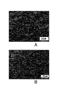
FIGS. LA and 1B show images of the microstructures of
Comparative Example 6 (FIG. 1A) and Inventive Example 5
(FIG. 1B).
In Comparative Example 6 having low-dislocation-
density bainite in a fraction of less than 80%, fine
bainite was formed because the cooling end temperature of
Comparative Example 6 was set to be a low value. However,
since Inventive Example 5 was cooled to a cooling end
temperature satisfying the range proposed in the present
disclosure and had low-dislocation-density bainite in a
fraction of 80% or greater, Inventive Example 5 had a
greater grain size than Comparative Example 6, but very
lower dislocation density than Comparative Example 6 owing
to a recovery phenomenon.
Page 39
1