Note: Descriptions are shown in the official language in which they were submitted.
CA 03043778 2019-05-14
WO 2018/100152 PCT/EP2017/081178
1
Title: Method and system for manufacturing a shear web for a wind turbine
blade
Field of the Invention
The present invention relates to a method and to a mould system for
manufacturing a
shear web for a wind turbine blade as well as to a backing plate for such
method and
mould system.
Background of the Invention
Wind turbine blades are often manufactured according to one of two
constructional de-
signs, namely a design where a thin aerodynamic shell is glued or otherwise
bonded
onto a spar beam, or a design where spar caps, also called main laminates, are
inte-
grated into the aerodynamic shell.
In the first design, the spar beam constitutes the load bearing structure of
the blade.
The spar beam as well as the aerodynamic shell or shell parts are manufactured
sepa-
rately. The aerodynamic shell is often manufactured as two shell parts,
typically as a
pressure side shell part and a suction side shell part. The two shell parts
are glued or
otherwise connected to the spar beam and are further glued to each other along
a
leading edge and trailing edge of the shell parts. This design has the
advantage that
the critical load carrying structure may be manufactured separately and
therefore is
easier to control. Further, this design allows for various different
manufacturing meth-
ods for producing the beam, such as moulding and filament winding.
In the second design, the spar caps or main laminates are integrated into the
shell and
are moulded together with the aerodynamic shell. The main laminates typically
com-
prise a high number of fibre layers compared to the remainder of the blade and
may
form a local thickening of the wind turbine shell, at least with respect to
the number of
fibre layers. Thus, the main laminate may form a fibre insertion in the blade.
In this de-
sign, the main laminates constitute the load carrying structure. The blade
shells are
typically designed with a first main laminate integrated in the pressure side
shell part
and a second main laminate integrated in the suction side shell part. The
first main
laminate and the second main laminate are typically connected via one or more
shear
webs, which for instance may have a C-shaped or l-shaped cross-section. For
very
long blades, the blade shells may further along at least a part of the
longitudinal extent
CA 03043778 2019-05-14
WO 2018/100152 PCT/EP2017/081178
2
comprise an additional first main laminate in the pressure side shell, and an
additional
second main laminate in the suction side shell. These additional main
laminates may
also be connected via one or more shear webs. This design has the advantage
that it is
easier to control the aerodynamic shape of the blade via the moulding of the
blade
shell part.
The shear webs act to reinforce the blade structure, and prevent excessive
bending or
buckling. Some blade designs use shear webs formed from beam members having l-
or C-shaped cross-sections, the members having a main body with load-bearing
flanges extending therefrom at opposed ends of the main body.
One method of manufacturing such l- or C-webs is through the provision of a
sandwich
panel body to which layers of fibre material are applied at the opposed ends
in the
shape of the desired flanges, the fibre material being infused with a resin
and
subsequently cured to form rigid flanges.
It is well-known to manufacture such shear webs in a suitably shaped mould
structure,
wherein a C-web can be manufactured using a relatively simple U-shaped mould,
where the sandwich panel body extends between opposed walls of the mould
structure, with the flanges formed through the layup of fibre material against
the said
walls.
Similarly, an l-web can be manufactured using a mould having a central support
bounded by flexible support members on either side to define an adjustable
void
between the flexible support members and the opposed mould walls. In this
situation,
the sandwich panel body is arranged on the central support, while the
adjustable void
is arranged to receive fibre layers to form the flanges on a first side of the
panel body,
with the flanges on the second side of the panel body formed by the layup of
fibre
material against the opposed mould walls.
Such resin-infused fibre-based flanges are often the target for the prevention
of
structural faults and cracks, due to the relatively large forces transferred
through said
flanges. International Patent Application Publication No. WO 2016/066816 Al
discloses
a method and mould system for manufacturing l-shaped shear webs for wind
turbine
blades. The mould system comprises a lower web mould part having a concave
shape
with diverging side parts for manufacturing first sides of l-web foot flanges,
and an
CA 03043778 2019-05-14
WO 2018/100152 PCT/EP2017/081178
3
upper mould part having a concave shape with converging side parts for
manufacturing
other sides of the l-web foot flanges.
In such prior art systems, resin is typically infused into the mould cavity
at, or close to,
the centre of the web body. This has been observed by the present inventors to
result
in dissatisfying flow patterns and resulting structural properties throughout
the shear
web.
It is an object of the invention to provide an alternative system and method
for the
manufacture of shear webs, which provides for increased ease of manufacturing
combined with a reduced risk of structural failure.
It is a further object of the present invention to provide a system and method
for the
manufacture of shear webs that is simple and cost-effective.
It is another object of the present invention to provide a system and method
for the
manufacture of shear webs that is flexible and applicable to a number of
different
moulding situations.
Summary of the Invention
It has been found that one or more of the aforementioned objects can be
obtained by a
method of manufacturing a shear web for a wind turbine blade, the shear web
having a
web body and a first web foot flange at a first end of the web body and a
second web
foot flange at a second end of the web body, wherein the method comprises the
steps
of:
a) providing an elongated lower web mould part having a moulding surface with
a
central portion, which is substantially flat, a first downwardly extending
moulding sur-
face portion at a first end of the lower web mould part, and a second
downwardly ex-
tending moulding surface portion at a second end of the lower web mould part,
b) arranging one or more fibre layers on top of the elongated lower web
mould part
and at least partly covering the first downwardly extending moulding surface
portion,
the central portion, and the second downwardly extending moulding surface
portion,
c) arranging a first backing plate opposite to the first downwardly
extending moulding
surface portion and arranging a second backing plate opposite to the second
down-
CA 03043778 2019-05-14
WO 2018/100152 PCT/EP2017/081178
4
wardly extending moulding surface portion to create a mould cavity between the
first
and second backing plates and the lower web mould part, wherein each backing
plate
comprises an inner moulding surface, one or more outer surfaces, and a channel
or
groove extending between at least one of the outer surfaces and the inner
moulding
.. surface of the backing plate,
d) supplying resin to the mould cavity via the respective channel or groove
of the first
and second backing plate, and
e) curing or hardening the resin in order to form the shear web.
It has been surprisingly found that such resin infusion from the foot flange
of the later
shear web, unlike the common infusion at the web body, leads to improved flow
pat-
terns resulting in better structural stability and less repairs. Also, this
results in a very
cost-effective mould system and time-efficient process setup due to the flow
channel or
groove in the backing plates. The backing plates may be made of non-costly
materials,
such as one or more polymers, and may be reusable. In addition, they are
compatible
for manufacturing shear webs across different blade types. Preferably, the
backing
plates are reusable.
Typically, the outer surfaces of the backing plate include an opposing back
surface that
is substantially parallel to the inner moulding surface, and four lateral
surfaces, such as
a right, left, top and bottom lateral surface. Preferably, the channel or
groove extends
between one of more of the lateral surfaces and the inner moulding surface of
the
backing plate.
Advantageously, the lower web mould part has an overall concave shape with
diverg-
ing side parts for manufacturing first sides of the web foot flanges. A set of
first fibre
layers may be draped over the concave moulding surface of the web part. The
first fi-
bre layers will ideally comply with the moulding surface of the lower mould.
Preferably, the lower web mould part comprises magnetic material, wherein the
first
and/or second backing plate further comprises a recess in its outer surface
and where-
in one or more magnets are arranged in the recess for retaining the backing
plate
against the lower web mould part during moulding. This solution has been found
to re-
sult in extremely fast mounting of the backing plates and a very low risk for
leaks. The
entire system can be placed under a vacuum bag. The magnetic material of the
lower
CA 03043778 2019-05-14
WO 2018/100152 PCT/EP2017/081178
web mould part may be steel or steel in combination with one or more other
compo-
nents. Thus, the lower web mould part may substantially consist of steel.
In a preferred embodiment, the recess of the backing plate is located in an
opposing
5 back surface that is substantially parallel to the inner moulding surface of
the backing
plate.
Preferably, the shear web is substantially l-shaped. By substantially l-shaped
is meant
that the shear web has a shear web body and a first web foot flange at a first
end of the
web body, where a first flange part extends from a first side of the web body
and a
second flange part extends from a second side of the web body, and further a
second
web foot flange at a second end of the web body, where a first flange part
extends from
a first side of the web body and a second flange part extends from a second
side of the
web body.
In a preferred embodiment, the outer surface of each backing plate comprises a
lateral
surface, wherein the channel leads from said lateral surface to the inner
moulding sur-
face of the backing plate. The lateral surface may, for example, be a left
side surface or
a right side surface of the backing plate.
In a particularly preferred embodiment, the outer surfaces of each backing
plate com-
prise two opposing lateral surfaces, and wherein the groove is extending
throughout
the inner moulding surface between the two opposing lateral surfaces of the
backing
plate. The opposing lateral surfaces may for example be a right hand surface
and an
opposing left hand lateral surface of the backing plate. In such embodiments,
the back-
ing plate can be advantageously manufactured by an extrusion process.
According to another embodiment, the first downwardly extending moulding
surface
portion and/or the second downwardly extending moulding surface portion
comprises a
ledge which forms part of the moulding surface of the lower web mould part.
The ledge
may define an end section of the side of the web foot flange and/or may be
used for
supporting the external web foot flange.
In a preferred embodiment, the first and the second downwardly extending
moulding
surface portion of the lower web mould part are diverging from the central
portion along
at least a part of the elongated lower web mould part.
CA 03043778 2019-05-14
WO 2018/100152 PCT/EP2017/081178
6
According to another embodiment, step b) further comprises arranging a core
material,
such as balsawood or foamed polymer, on top of the one or more fibre layers in
the
central part of the lower web mould part, optionally followed by arranging one
or more
fibre layers on top of the core material. Advantageously, the core material is
of low
density, such as balsawood, foamed polymer or the like. Thus, the web body of
the
shear web may be formed as a sandwich construction having a set of first fibre
layers
as a first skin, a core material in the middle, and a set of second fibre
layers as a sec-
ond skin.
Additionally, a set of third fibre layers may be provided for the first web
foot flange, and
a set of fourth fibre layers may be provided for the second web foot flange.
The addi-
tional third and fourth fibre layers may form the bonding surfaces of the web
foot flang-
es. An infusion mesh and/or peel ply may be applied on top of the third and/or
fourth
fibre layers prior to arranging the backing plates in their positions.
It is preferred that step c) further comprises retaining one or more of the
fibre layers
against the inner moulding surface of the first and/or the second backing
plate. This
may be achieved by retaining means, such as a tackifier, a clamp, or magnets.
Alterna-
tively, one or more of the fibre layers may be wrapped around a top part of
the backing
plates
According to another embodiment, step b) further comprises arranging an upper
web
mould part on top of the fibre layers, the upper web mould part having a
moulding sur-
face with a central portion, which is substantially flat, a first upwardly
extending mould-
ing surface portion at a first end of the upper web mould part, and a second
upwardly
extending moulding surface portion at a second end of the upper web mould
part, and
wherein step b) optionally comprises wrapping ends of the second fibre layers
against
the first and the second upwardly extending moulding surface of the upper web
mould
part.
In a preferred embodiment, the first and the second upwardly extending
moulding sur-
face portion of the upper web mould part are converging from the central
portion along
at least a part of the elongated upper web mould part.
CA 03043778 2019-05-14
WO 2018/100152 PCT/EP2017/081178
7
According to an advantageous embodiment, the angle of the first downwardly
extend-
ing moulding surface portion is substantially equal to the angle of the first
upwardly ex-
tending surface portion. Thereby, the two web mould parts allow a
substantially straight
first web foot flange to be formed.
Preferably, the angle of the second downwardly extending moulding surface
portion is
substantially equal to the angle of the second upwardly extending surface
portion,
whereby a substantially straight second web foot flange may be formed.
The width of the central part of the upper web mould part preferably
corresponds to the
width of the central part of the lower web mould part. The width of the upper
web mould
part may also be slightly less that the width of the lower web mould part in
order to ac-
commodate for the converging web foot flanges.
A set of second fibre layers may be draped to the side flanges of the upper
web mould
part by first arranging the second fibre layers so that they are draped on top
of the first
fibre layers and optional core material parts. After the upper web mould part
has been
arranged on top of the second fibre layers, the ends of the second fibre
layers may
simply be wrapped against the side flanges of the upper web mould part.
According to another embodiment, the mould cavity is further sealed by at
least one
vacuum bag. The vacuum bag may be placed at least on top of the array of fibre
layers
and optional core material that has been arranged on the lower web mould part.
In
such embodiments, the mould cavity is delimited by the backing plates, the
lower web
mould part and the vacuum bag. In another embodiment, the vacuum bag may be
placed over at least part of the outer back surface of the backing plates.
Typically, the mould cavity prior to supplying the resin is evacuated by use
of a vacuum
source. Thus, it is seen that the shear web may be manufactured via a Vacuum
Assist-
ed Resin Transfer Moulding (VARTM) process. In principle, it is also possible
to use
RTM, where resin is injected into the mould cavity by use of an over-pressure.
The res-
in is preferably injected into the mould cavity, e.g. by drawing the resin in
via the vacu-
um or under-pressure. However, it is in principle also possible to use prepreg
material
for some of the fibre layers.
CA 03043778 2019-05-14
WO 2018/100152 PCT/EP2017/081178
8
Usually, after step e) the backing plates, and optionally the upper web mould
part, are
removed from the shear web, and the shear web in a following step is removed
from
the lower web mould part. This may simply be done by lifting the wind turbine
compo-
nent from the lower web mould part, which can easily be done, since the side
parts of
the lower mould are diverging from the central part of the mould part. The
lower mould
part is advantageously coated with a release agent so that the wind turbine
component
easily may be lifted from the surface of the lower web mould part.
According to an advantageous embodiment, at least a first insert is arranged
at the first
end of the lower web part, wherein said first insert is adapted to provide a
gradual tran-
sition from the web body to the first web foot flange and/or a second insert
is arranged
at the first end of the lower web part, wherein said first insert is adapted
to provide a
gradual transition from the web body to another part of the first web foot
flange, the first
insert and/or the second insert being e.g. substantially wedge shaped.
The first insert and/or the second insert may advantageously be substantially
wedge
shaped. Thus, the insert may have an overall triangular appearance. In an
advanta-
geous embodiment, the inserts have a rounded outer surface, which the first
fibre lay-
ers and the second fibre layers, respectively, may abut so that a round
transition is ob-
tamed from the web body to the first web foot flange. In principle, the
transition may al-
so be obtained by a single insert. The shear web will preferably have similar
inserts at
the transition between the web body and the second web foot flange. The
insert(s) may
be made of a core material, such as balsawood or foamed polymer. It may also
be
made of a fibre-reinforced polymer material and may be a pultruded or extruded
ele-
ment.
The first fibre layers and second fibre layers are preferably glass fibres.
They may also
include carbon fibres, aramid fibres, hemp fibres or the like.
According to another embodiment, one or more of the fibre layers are cut along
lower
surfaces of the downwardly extending moulding surface portions or, optionally,
along
upper surfaces of the upwardly extending moulding surface portions. A set of
first fibre
layers may simply be draped over the lower web mould part and then cut to the
correct
width by using a cutter, such as a sonic knife, along the edges of the lower
mould part.
CA 03043778 2019-05-14
WO 2018/100152 PCT/EP2017/081178
9
In another aspect, the present invention relates to a mould system for
manufacturing a
shear web for a wind turbine blade, the shear web having a web body and a
first web
foot flange at a first end of the web body and a second web foot flange at a
second end
of the web body, wherein the system comprises:
- an elongated lower web mould part having a moulding surface with a central
por-
tion, which is substantially flat, a first downwardly extending moulding
surface
portion at a first end of the lower web mould part, and a second downwardly ex-
tending moulding surface portion at a second end of the lower web mould part,
- two backing plates each comprising an inner moulding surface, one or more
outer
surfaces and a channel or groove extending between at least one of the outer
surfaces and the inner moulding surface for supplying resin through the
channel
or groove into a mould cavity.
In a preferred embodiment, the lower web mould part comprises magnetic
material,
and wherein the first and/or second backing plate further comprises a recess
in its out-
er surface and wherein one or more magnets are arranged in the recess for
retaining
the backing plate against the lower web mould part during moulding.
According to another embodiment, the recess of the backing plate is located in
an op-
posing back surface that is substantially parallel to the inner moulding
surface of the
backing plate.
In a preferred embodiment, the outer surface of each backing plate comprises a
lateral
surface, wherein the channel leads from said lateral surface to the inner
moulding sur-
face of the backing plate.
In another embodiment, the outer surfaces of each backing plate comprise two
oppos-
ing lateral surfaces, and wherein the groove is extending throughout the inner
moulding
surface between the two opposing lateral surfaces of the backing plate.
Advantageously, the first downwardly extending moulding surface portion and/or
the
second downwardly extending moulding surface portion comprises a ledge which
forms
part of the moulding surface of the lower web mould part.
CA 03043778 2019-05-14
WO 2018/100152 PCT/EP2017/081178
According to another embodiment, the first and the second moulding surface
portion
are diverging from the central portion along at least a part of the elongated
lower web
mould part.
5 According to another embodiment, the mould system further comprises an
elongated
upper web mould part having a moulding surface with a central portion, which
is sub-
stantially flat, a first upwardly extending moulding surface portion at a
first end of the
upper web mould part, and a second upwardly extending moulding surface portion
at a
second end of the upper web mould part.
According to another embodiment, the first and the second moulding surface
portions
of the elongated upper web mould part are converging from the central portion
along at
least a part of the elongated upper web mould part.
In a preferred embodiment, the angle of the first downwardly extending
moulding sur-
face portion is substantially equal to the angle of the first upwardly
extending surface
portion and/or the angle of the second downwardly extending moulding surface
portion
is substantially equal to the angle of the second upwardly extending surface
portion.
Preferably, the first downwardly extending surface portion has an end portion,
which
corresponds to an end portion of the first web foot flange, and wherein the
second
downwardly extending surface portion has an end portion, which corresponds to
an
end portion of the second web foot flange.
It is also preferred that the first upwardly extending surface portion has an
end portion,
which corresponds to an end portion of the first web foot flange, and wherein
the sec-
ond upwardly extending surface portion has an end portion, which corresponds
to an
end portion of the second web foot flange.
In a preferred embodiment, the lower web mould part and/or the upper web mould
part
are made of a foamed polymer covered by a hard surface coating, which provides
the
moulding surface. According to one embodiment, the hard surface coating is
made
from a polyurea material.
CA 03043778 2019-05-14
WO 2018/100152 PCT/EP2017/081178
11
According to another embodiment, the lower web mould part is modular having a
cen-
tral mould part with a raised central part, which comprises a first side wall
and a second
side wall, wherein
- a first mould insert is arranged at the first side wall of the raised
central part so
as to form the first downwardly extending moulding surface portion of the
lower web
mould part, and/or
- a second mould insert is arranged at the second side wall of the raised
central
part so as to form the first downwardly extending moulding surface portion of
the lower
web mould part.
In a preferred embodiment, the upper web mould part is modular and comprises a
first
upper web mould part for forming the first upwardly extending moulding surface
portion
and a second upper web mould part for forming the second upwardly extending
mould-
ing surface portion.
The mould system may be sectionised, in particular in the longitudinal or
spanwise di-
rection of the mould system. Thus, one section may manufacture a first
longitudinal
section of the shear web (or spar beam) and another section may manufacture a
sec-
ond longitudinal section of the shear web. The sectionised mould system may
prefera-
bly be assembled so that the shear web may be manufactured as a unitary
structure.
According to another aspect, the present invention relates to a backing plate
for manu-
facturing a shear web for a wind turbine blade, the backing plate comprising
an inner
moulding surface, one or more outer surfaces and a channel or groove extending
be-
tween at least one of the outer surfaces and the inner moulding surface for
supplying
resin through the channel or groove into a mould cavity.
In a preferred embodiment, the backing plate further comprises a recess in its
outer
surface, wherein one or more magnets are arrangable in the recess for
retaining the
backing plate against a lower web mould containing magnetic material.
According to another embodiment, the recess of the backing plate is located in
an op-
posing back surface that is substantially parallel to the inner moulding
surface of the
backing plate.
CA 03043778 2019-05-14
WO 2018/100152 PCT/EP2017/081178
12
In a preferred embodiment, the outer surface of each backing plate comprises a
lateral
surface, and wherein the channel leads from said lateral surface to the inner
moulding
surface of the backing plate. In a particularly preferred embodiment, the
outer surfaces
of the backing plate comprise two opposing lateral surfaces, and wherein the
groove is
extending throughout the inner moulding surface between the two opposing
lateral sur-
faces of the backing plate. As discussed above, such backing plate can
advantageous-
ly be manufactured using an extrusion process.
The channel or groove may have a width in the range between 10 and 50 mm,
advan-
tageously between, 15 and 45 mm, more advantageously between 20 and 40 mm. Fur-
ther, the channel or groove has a height in the range between 5 and 25 mm,
advanta-
geously between, 5 and 20 mm, more advantageously between 8 and 16 mm. Addi-
tionally, the channel or groove has a cross-sectional area in the range
between 50 and
500 mm2, advantageously between, 100 and 400 mm2, more advantageously between
150 and 350 mm2.
In another aspect, the present invention relates to a method of manufacturing
a shear
web for a wind turbine blade, the shear web having a web body and a first web
foot
flange at a first end of the web body and a second web foot flange at a second
end of
the web body, wherein the method comprises infusing resin into a mould cavity
such
that the resin flows from a region forming the first and second web foot
flange towards
a region forming the web body of the shear web. The present invention also
relates to a
shear web obtainable by said process.
In another aspect, the present invention relates to a method of manufacturing
at least a
part of a wind turbine blade comprising manufacturing at least one shear web
as de-
scribed above, and joining said at least one shear web to a second component
to form
at least a part of a wind turbine blade.
There is further provided a shear web manufactured according to the above-
described
method. There is further provided a wind turbine blade comprising a shear web
as de-
scribed above. There is further provided a wind turbine comprising at least
one wind
turbine blade as described above.
As used herein, the term "outer surface(s)" of a backing plate refers to any
surface that
does not form part of the inner moulding surface of the backing plate, i.e.
any surface
CA 03043778 2019-05-14
WO 2018/100152 PCT/EP2017/081178
13
that is external to the mould cavity. Such outer surface(s) may include an
opposing
back surface that is substantially parallel to the inner moulding surface or
lateral sur-
faces of the backing plate. The lateral surfaces of the backing plate
typically include
four lateral surfaces, i.e. including a right and a left side surface and a
top and bottom
side surface.
As used herein, the term "magnetic material" refers to materials that are
attracted to a
magnet, such as ferromagnetic materials.
Description of the Invention
The invention is explained in detail below with reference to an embodiment
shown in
the drawings, in which
Fig. 1 shows a wind turbine,
Fig. 2 shows a schematic view of a wind turbine blade,
Fig. 3 shows a schematic view of a cross-section of a wind turbine blade,
Fig. 4 shows a schematic view of a cross-section of a shear web mould system
accord-
ing to the present invention,
Fig. 5 shows a schematic view of a cross-section of another embodiment of a
shear
web mould system according to the present invention,
Fig. 6 shows a schematic view of a cross-section of another embodiment of a
shear
web mould system according to the present invention,
Fig. 7 shows a perspective view of a backing plate according to the present
invention,
Fig. 8 shows a partially cut-away perspective view of a backing plate
according to the
present invention,
CA 03043778 2019-05-14
WO 2018/100152 PCT/EP2017/081178
14
Fig. 9 shows a perspective view of a backing plate according to another
embodiment of
the present invention, and
Fig. 10 shows a perspective view of a backing plate according to yet another
embodi-
ment of the present invention.
Detailed Description
Fig. 1 illustrates a conventional modern upwind wind turbine according to the
so-called
"Danish concept" with a tower 4, a nacelle 6 and a rotor with a substantially
horizontal
rotor shaft. The rotor includes a hub 8 and three blades 10 extending radially
from the
hub 8, each having a blade root 16 nearest the hub and a blade tip 14 farthest
from the
hub 8. The rotor has a radius denoted R.
Fig. 2 shows a schematic view of a wind turbine blade 10. The wind turbine
blade 10
has the shape of a conventional wind turbine blade and comprises a root region
30
closest to the hub, a profiled or an airfoil region 34 farthest away from the
hub and a
transition region 32 between the root region 30 and the airfoil region 34. The
blade 10
comprises a leading edge 18 facing the direction of rotation of the blade 10,
when the
blade is mounted on the hub, and a trailing edge 20 facing the opposite
direction of the
leading edge 18.
The airfoil region 34 (also called the profiled region) has an ideal or almost
ideal blade
shape with respect to generating lift, whereas the root region 30 due to
structural con-
siderations has a substantially circular or elliptical cross-section, which
for instance
makes it easier and safer to mount the blade 10 to the hub. The diameter (or
the chord)
of the root region 30 may be constant along the entire root area 30. The
transition re-
gion 32 has a transitional profile gradually changing from the circular or
elliptical shape
of the root region 30 to the airfoil profile of the airfoil region 34. The
chord length of the
transition region 32 typically increases with increasing distance r from the
hub. The air-
foil region 34 has an airfoil profile with a chord extending between the
leading edge 18
and the trailing edge 20 of the blade 10. The width of the chord decreases
with increas-
ing distance r from the hub.
CA 03043778 2019-05-14
WO 2018/100152 PCT/EP2017/081178
A shoulder 40 of the blade 10 is defined as the position, where the blade 10
has its
largest chord length. The shoulder 40 is typically provided at the boundary
between the
transition region 32 and the airfoil region 34.
5 It should be noted that the chords of different sections of the blade
normally do not lie
in a common plane, since the blade may be twisted and/or curved (i.e. pre-
bent), thus
providing the chord plane with a correspondingly twisted and/or curved course,
this be-
ing most often the case in order to compensate for the local velocity of the
blade being
dependent on the radius from the hub.
The blade is typically made from a pressure side shell part 36 and a suction
side shell
part 38 that are glued to each other along bond lines at the leading edge 18
and the
trailing edge of the blade 20.
Fig. 3 shows a schematic view of a cross section of the blade along the line I-
I shown
in Fig. 2. As previously mentioned, the blade 10 comprises a pressure side
shell part
36 and a suction side shell part 38. The pressure side shell part 36 comprises
a spar
cap 41, also called a main laminate, which constitutes a load bearing part of
the pres-
sure side shell part 36. The spar cap 41 comprises a plurality of fibre layers
42 mainly
comprising unidirectional fibres aligned along the longitudinal direction of
the blade in
order to provide stiffness to the blade. The suction side shell part 38 also
comprises a
spar cap 45 comprising a plurality of fibre layers 46. The pressure side shell
part 38
may also comprise a sandwich core material 43 typically made of balsawood or
foamed
polymer and sandwiched between a number of fibre-reinforced skin layers. The
sand-
wich core material 43 is used to provide stiffness to the shell in order to
ensure that the
shell substantially maintains its aerodynamic profile during rotation of the
blade. Simi-
larly, the suction side shell part 38 may also comprise a sandwich core
material 47.
The spar cap 41 of the pressure side shell part 36 and the spar cap 45 of the
suction
side shell part 38 are connected via a first shear web 50 and a second shear
web 55.
The shear webs 50, 55 are in the shown embodiment shaped as substantially l-
shaped
webs. The first shear web 50 comprises a shear web body and two web foot
flanges.
The shear web body comprises a sandwich core material 51, such as balsawood or
foamed polymer, covered by a number of skin layers 52 made of a number of
fibre lay-
ers. The second shear web 55 has a similar design with a shear web body and
two
web foot flanges, the shear web body comprising a sandwich core material 56
covered
CA 03043778 2019-05-14
WO 2018/100152 PCT/EP2017/081178
16
by a number of skin layers 57 made of a number of fibre layers. The sandwich
core
material 51, 56 of the two shear webs 50, 55 may be chamfered near the flanges
in or-
der to transfer loads from the webs 50, 55 to the main laminates 41, 45
without the risk
of failure and fractures in the joints between the shear web body and web foot
flange.
However, such a design will normally lead to resin rich areas in the joint
areas between
the legs and the flanges. Further, such resin rich area may comprise burned
resin due
to high exothermic peeks during the curing process of the resin, which in turn
may lead
to mechanical weak points.
In order to compensate for this, a number of filler ropes 60 comprising glass
fibres are
normally arranged at these joint areas. Further, such ropes 60 will also
facilitate trans-
ferring loads from the skin layers of the shear web body to the flanges.
However, ac-
cording to the invention, alternative constructional designs are possible.
The blade shells 36, 38 may comprise further fibre-reinforcement at the
leading edge
and the trailing edge. Typically, the shell parts 36, 38 are bonded to each
other via glue
flanges in which additional filler ropes may be used (not shown).
Additionally, very long
blades may comprise sectional parts with additional spar caps, which are
connected
via one or more additional shear webs.
Fig. 4 illustrates a method of manufacturing a shear web for a wind turbine
blade ac-
cording to the present invention. The shear web mould system 70 of Fig. 4
comprises a
lower mould part 61 and a first backing plate 66 for forming an outer surface
of a first
web foot flange of the shear web, and a second backing plate 68 for forming an
outer
surface of a second web foot flange of the shear web. The lower web mould part
61
has a moulding surface, which defines an outer part of a shear web
manufactured via
the shear web moulding system. The moulding surface comprises a central
portion 71,
which is substantially flat, and which is utilised to form a web body of the
shear web.
Further, the lower web mould part 61 comprises a first side part at a first
side end of
the lower web mould part 61, the first side part having a first downwardly
extending
moulding surface portion 72. Similarly, the lower web mould part 61 comprises
a sec-
ond side part at a second side end, the second side part having a second
downwardly
extending moulding surface portion 73. The first and the second moulding
surface por-
tions 72, 73 are diverging from the central portion 71 along at least a part
of the elon-
gated lower web mould part 61.
CA 03043778 2019-05-14
WO 2018/100152 PCT/EP2017/081178
17
The process according to the present invention may involve arranging a number
of first
fibre layers 62 on top of the lower web mould part 61 and covering the
downwardly ex-
tending moulding surface portions 72, 73 of the lower web mould part 61. The
first fibre
layers 62 form part of an outer skin of the finished shear web. A core
material 63, such
as balsawood or foamed polymer, is arranged on top of the first fibre layers
62 in the
central portion 71 of the lower web mould part 61. Thus, the web body of the
shear web
may be formed as a sandwich construction having the first fibre layers 62 as a
first skin
and second fibre layers 64 as a second skin. Further, a first insert 74 may be
arranged
at the first side end of the lower web mould part 61 and at a first side of
the core mate-
rial 63. The first insert 74 may have a shape so as to provide a gradual
transition from
the web body to a first web foot flange. Similarly, a second insert 75 may be
arranged
at the second side end of the lower web mould part 61 and at the first side of
the core
material 63. The second insert 75 may have a shape so as to provide a gradual
transi-
tion from the web body to a second web foot flange.
A number of second fibre layers 64 are arranged on top of the core material
63. Fur-
ther, a third insert 76 may be arranged at the first side end of the lower web
mould part
61 and at a second side of the core material 63. The third insert 76 may have
a shape
so as to provide a gradual transition from the web body to a first web foot
flange. Simi-
larly, a fourth insert 77 may be arranged at the second side end of the lower
web part
61 and at the second side of the core material 63. The fourth insert 77 may
have a
shape so as to provide a gradual transition from the web body to a second web
foot
flange. Additionally, a number of third fibre layers 78 may be provided for
the first web
foot flange, and a number of fourth fibre layers 79 may be provided for the
second web
foot flange. The additional fibre layers 78, 79 may form the bonding surfaces
of the web
foot flanges. An infusion mesh and/or peel ply may be applied on top of the
third and/or
fourth fibre layers prior to arranging the backing plates in their positions,
or they may
replace the third and/or fourth fibre layers.
Once the first fibre reinforcement layers 62 making up the first skin of the
shear web
body and the first sides of the web foot flanges, and optionally the core
material and/or
any inserts, are arranged on top of the lower web mould part 61, the first
backing plate
66 is clamped against the first fibre layers 62 and the first downwardly
extending
moulding surface portion 72 of the lower web mould part 61 by use of a first
clamp 67.
Similarly, the second backing plate 68 is clamped against the first fibre
layers 64 and
the second downwardly extending moulding surface portion of the lower web
mould
CA 03043778 2019-05-14
WO 2018/100152 PCT/EP2017/081178
18
part 61 by use of a second clamp 69. Each backing plate 66, 68 comprises a
respec-
tive inner moulding surface 80a, 80b and a groove 83a, 83b extending
throughout the
moulding surface between two opposing lateral surfaces (best seen in Fig. 9).
The second fibre layers 64 making up the second skin of the shear web body and
the
second sides of the web foot flanges may be wrapped around a top part of the
backing
plates 66, 68, or they may be retained against the moulding surfaces of the
two back-
ing plates by retaining means, such as a tackifier, a clamp, or magnets.
Once the fibre material 62, 64, 78, 79, core material 63, and possible inserts
74, 75, 76,
77 have been arranged, a vacuum foil (not shown) is arranged on top of the
material
and the shear web mould system 70, and in a next step, not shown, a vacuum
source
is connected to the mould cavity, and the mould cavity is evacuated by use of
the vac-
uum source. The mould cavity is further connected to a resin source, and
liquid resin is
injected into the mould cavity so as to wet the fibre material and the core
material. The
resin is supplied to the mould cavity between the backing plates 66, 68 and
the lower
mould part 61 via each of the grooves 83a, 83b of the first and second backing
plates
66, 68. Subsequently, the resin is cured or hardened to form the shear web.
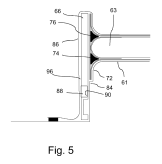
Fig. 5 illustrates another embodiment of a mould system of the present
invention (only
one end shown in cross sectional view). Here, the lower mould part 61
comprises a
ledge 84 within the downwardly extending moulding surface portion 72. The
ledge 84
may define an end section of the side of the web foot flange and/or may be
used for
carrying the external web foot flange. In such a setup, it might not be
necessary to use
clamps. The backing plate 66 further comprises a recess 90 wherein a magnet 88
is ar-
ranged in the recess for retaining the backing plate 66 in its position during
moulding.
In such embodiments it is preferred that the lower mould part 61 comprises
steel or
substantially consists of steel. A vacuum bag 86 is placed on top of the array
of fibre
layers and core material on the lower web mould part and over the back surface
96 of
the backing plate 66.
An alternative embodiment of a mould system of the present invention is
illustrated in
Fig. 6 (only one end shown in cross sectional view). The web mould system of
Fig. 6
comprises both a lower web mould part 61 and an upper web mould part 65. The
web
mould parts may for instance comprise a core part made of a foamed polymer,
which is
covered by a hard surface coating, e.g. a polyurea material. The upper web
mould part
CA 03043778 2019-05-14
WO 2018/100152 PCT/EP2017/081178
19
65 comprises a moulding surface with a central portion 91, which is
substantially flat, a
first upwardly extending moulding surface portion 93 at a first end of the
upper web
mould part 65, and a second upwardly extending moulding surface portion at a
second
end of the upper web mould part (not shown).
The fibre material 62, 64 and core material 63 forming part of the finished
shear web is
arranged between the lower web mould part 61 and the upper web mould part 65.
The
lower web mould part 61 is provided with a ledge 84, for defining an end
section of the
first side of the web foot flange and/or may be used for carrying the external
web foot
flange. As in the previously described embodiment, the backing plate 66
contains a
groove 83 extending between opposing outer lateral surfaces. A vacuum bag 86
is ar-
ranged on top of the two web mould parts 61, 65 and the backing plate 66.
Resin is
then injected through the groove 83 and finally hardened or cured in order to
form the
final shear web.
The reinforcement fibre material described for the various embodiments is
preferably
glass fibres. However, it could also be other suitable fibre reinforcement
material, such
as carbon fibres. While the various embodiments have been shown for shear webs
having a rounded transition from the web body to the web foot flange, it is
also recog-
nized that an angled configuration between the two parts may be utilised
instead.
Figs. 7 and 8 further illustrate some details of a backing plate 66 according
to one em-
bodiment of the present invention, wherein Fig. 8 is a cut-away perspective
view of the
backing plate 66 cut open along the plane A in Fig. 7. The backing plate 66
comprises
a moulding surface 80 which faces the mould cavity during moulding of the
shear web
according to the present invention. It also comprises an opposing outer back
surface
96 that is substantially parallel to the inner moulding surface and facing
away from the
mould cavity during operation. Also, the backing plate comprises a lateral
surface 98
containing an opening 92. As can be seen in Fig. 8, the opening 92 is part of
an inte-
grated channel 82 leading to an opening 94 in the moulding surface 80 of the
backing
plate. Thus, during operation, resin flows through the opening 92, through the
channel
82, through the opening 94 and finally into the mould cavity to mould the
shear web.
Fig. 9 shows a perspective view of a backing plate 66 according to another
embodi-
ment of the present invention. The backing plate 66 comprises a moulding
surface 80
which faces the mould cavity during moulding of the shear web according to the
pre-
CA 03043778 2019-05-14
WO 2018/100152 PCT/EP2017/081178
sent invention. It also comprises an opposing back surface 96 that is
substantially par-
allel to the inner moulding surface 80 and facing away from the mould cavity
during op-
eration. The backing plate 66 of Fig. 9 comprises a first lateral surface 98
and an op-
posing second lateral surface 100. It further comprises a third lateral
surface 102 and
5 an opposing fourth lateral surface 104. A groove 83 is extending across the
moulding
surface 80 between the two opposing lateral surfaces 98, 100. In this way,
resin can be
supplied to the mould cavity via the groove 83 from one or both lateral
surfaces of the
backing plate. This could be done, for example, by inserting a pipe or hose
into the
opening in one or both of the lateral surfaces 98, 100.
The invention has been described with reference to advantageous embodiments.
How-
ever, the scope of the invention is not limited to the illustrated
embodiments, and al-
terations and modifications can be carried out without deviating from the
scope of the
invention, which is defined by the claims.
Fig. 10 shows a side view of a backing plate 66' according to yet another
embodiment
of the present invention. The backing plate 66' comprises a moulding surface
80' which
faces the mould cavity during moulding of the shear web according to the
present in-
vention. It also comprises an opposing back surface 96' that is substantially
parallel to
the inner moulding surface 80' and facing away from the mould cavity during
operation.
A groove 83' is extending across the moulding surface 80' between two
transverse
sides of the backing plate 66'. In this way, resin can be supplied to the
mould cavity via
the groove 83' from one or both lateral surfaces of the backing plate in a
similar way to
that described in relation to Fig. 9. As shown in this embodiment, a recess
may be
formed in one of the surfaces of the backing plate, e.g. as shown in the back
surface
96'. A magnet 88' may be inserted in the recess, which may be closed or locked
in
place by use of a closure 89 or lid.
A height h of the groove 83, 83' may for instance be between 5 mm and 20 mm,
e.g.
around 12 mm. The width w of the groove 83, 83' may be between 15 mm and 55
mm,
e.g. around 31 mm or 32 mm. The area of the groove may be between 100 mm2 and
500 mm2, e.g. around 250 mm2.
The invention has been described with reference to advantageous embodiments.
How-
ever, the scope of the invention is not limited to the illustrated
embodiments, and al-
CA 03043778 2019-05-14
WO 2018/100152 PCT/EP2017/081178
21
terations and modifications can be carried out without deviating from the
scope of the
invention, which is defined by the claims.
List of reference numerals
4 tower
6 nacelle
8 hub
10 blades
14 blade tip
16 blade root
18 leading edge
trailing edge
15 30 root region
32 transition region
34 airfoil region
36 pressure side shell part
38 suction side shell part
20 40 shoulder
41 spar cap
42 fibre layers
43 sandwich core material
45 spar cap
46 fibre layers
47 sandwich core material
50 first shear web
51 sandwich core material of shear web
52 skin layers
55 second shear web
56 sandwich core material of second shear web
57 skin layers of second shear web
60 filler ropes
61 lower mould part
62 first fibre layers
63 core material
CA 03043778 2019-05-14
WO 2018/100152
PCT/EP2017/081178
22
64 second fibre layers
65 upper mould part
66, 66' first backing plate
67 first clamp
68 second backing plate
69 second clamp
70 web mould system
71 central portion
72 first downwardly extending moulding surface portion
73 second downwardly extending moulding surface portion
74 first insert
75 second insert
76 third insert
77 fourth insert
78 third fibre layers
79 fourth fibre layers
80, 80' inner moulding surface of backing plate
82 channel
83, 83' groove
84 ledge
86 vacuum foil
88, 88' magnet
89 closure
90 recess
91 central portion of moulding surface of upper web mould part
92 opening in side surface
93 upwardly extending moulding surface portion of upper web mould part
94 opening in inner moulding surface
96, 96' back surface of backing plate
98 first lateral surface of backing plate
100 second lateral surface of backing plate
102 third lateral surface of backing plate
104 fourth lateral surface of backing plate
R rotor radius
r distance from hub