Note: Descriptions are shown in the official language in which they were submitted.
CA 03044192 2019-05-16
-1-
MULTIVIEW DISPLAYS HAVING A REFLECTIVE SUPPORT STRUCTURE
BACKGROUND
[0001] Electronic displays are a nearly ubiquitous medium for communicating
information to users of a wide variety of devices and products. Most commonly
employed electronic displays include the cathode ray tube (CRT), plasma
display panels
(PDP), liquid crystal displays (LCD), electroluminescent displays (EL),
organic light
emitting diode (OLED) and active matrix OLEDs (AMOLED) displays,
electrophoretic
displays (EP) and various displays that employ electromechanical or
electrofluidic light
modulation (e.g., digital micromirror devices, electrowetting displays, etc.).
Generally,
electronic displays may be categorized as either active displays (i.e.,
displays that emit
light) or passive displays (i.e., displays that modulate light provided by
another source).
Among the most obvious examples of active displays are CRTs, PDPs and
OLEDs/AMOLEDs. Displays that are typically classified as passive when
considering
emitted light are LCDs and EP displays. Passive displays, while often
exhibiting
attractive performance characteristics including, but not limited to,
inherently low power
consumption, may find somewhat limited use in many practical applications
given the
lack of an ability to emit light.
[0002] In order to overcome the limitations of passive displays associated
with
emitted light, many passive displays are coupled to an external light source.
The coupled
light source may allow these otherwise passive displays to emit light and
function
substantially as an active display. Examples of such coupled light sources are
backlights.
A backlight may serve as a source of light (often a panel backlight) that is
placed behind
an otherwise passive display to illuminate the passive display. For example, a
backlight
may be coupled to an LCD or an EP display. The backlight emits light that
passes
through the LCD or the EP display. The light emitted is modulated by the LCD
or the EP
display and the modulated light is then emitted, in turn, from the LCD or the
EP display.
Often backlights are configured to emit white light. Color filters are then
used to
transform the white light into various colors used in the display. The color
filters may be
CA 03044192 2019-05-16
-2-
placed at an output of the LCD or the EP display (less common) or between the
backlight
and the LCD or the EP display, for example.
DESCRIPTION OF THE DRAWINGS
[0003] Various features of examples and embodiments in accordance with the
principles described herein may be more readily understood with reference to
the
following detailed description taken in conjunction with the accompanying
drawings,
where like reference numerals designate like structural elements, and in
which:
100041 Figure lA illustrates a perspective view of a multiview image
produced by
an example multiview display.
[0005] Figure 1B illustrates a graphical representation of angular
components of a
light beam emanating from a point of a multiview display.
[0006] Figure 2A illustrates an isometric view of an example multiview
display.
[0007] Figure 2B illustrates a cross-sectional view of the multiview
display
illustrated in Figure 2A.
[0008] Figure 2C shows an exploded isometric view of the multiview display
illustrated in Figure 2A.
[0009] Figure 3 illustrates a cross-sectional view of light coupled into a
plate light
guide of a multiview display.
[0010] Figure 4 illustrates total internal reflection at a surface of a
plate light
guide.
[0011] Figure 5 illustrates a cross-sectional view of a support layer, a
reflective
layer, and a plate light guide.
[0012] Figure 6A illustrates an exploded isometric view of an example
multiview
display configured with a segmented reflective layer.
[0013] Figure 6B illustrates an exploded isometric view of an example
multiview
display configured with a segmented reflective layer.
[0014] Figure 7 illustrates a cross-sectional view of an example multiview
display
configured with a reflective support layer.
[0015] Figure 8A illustrates a cross-sectional view of an example multibeam
element of a plate light guide configured as a transmittable diffraction
grating.
CA 03044192 2019-05-16
-3-
[0016] Figure 8B illustrates a cross-sectional view of an example multibeam
element of a plate light guide configured as a reflective diffraction grating.
[0017] Figure 9 illustrates a cross-sectional view of an example multibeam
element of a plate light guide configured as a micro-refractive element.
[0018] Figure 10A illustrates a cross-sectional view of an example
multibeam
element of a plate light guide configured as a prismatic-shaped micro-
reflective element.
[0019] Figure 10B illustrates a cross-sectional view of an example
multibeam
element of a plate light guide configured as a semi-spherical micro-refractive
element.
[0020] Figure 11 illustrates a flow diagram of a method to display
multiview
images.
[0021] Certain examples and embodiments may have other features that are
one
of in addition to and in lieu of the features illustrated in the above-
referenced figures.
These and other features are described below with reference to the above-
referenced
figures.
DETAILED DESCRIPTION
[0022] Examples and embodiments in accordance with the principles described
herein provide a multiview display comprising a reflective support structure
located
between a backlight and a screen. The reflective support structure is
configured to
maintain a substantially uniform separation distance between the screen and
the backlight
and to adhere or affix the screen to the backlight. In addition, reflective
properties of the
reflective support may 'recycle' light propagating within the backlight,
according to some
embodiments. In particular, the reflective support may recycle light by
substantially
reflecting light incident on the reflective support back into the light guide.
Recycling
light in this manner may prevent leakage or unwanted transmission of light
from the light
guide, according to various embodiments as described below.
[0023] A multiview display is an electronic display or display system
configured
to provide a plurality or number of different views of a multiview image in
different view
directions. The term `multiview' as used in the terms `multiview image' refers
to a
plurality or a number of views representing different perspective views or
including
angular disparity between views of the many different views. In addition, the
term
`multiview' includes more than two different views (i.e., a minimum of three
views and
CA 03044192 2019-05-16
-4-
generally more than three views). As such, a `multiview display' is
distinguished from a
stereoscopic display. A stereoscopic display displays only two different views
to
represent a scene or an image. Note however, while multiview images and
multiview
displays include more than two views, multiview images may be viewed (e.g., on
a
multiview display) as a stereoscopic pair of images by selecting only two of
the
multiview views to view at a time (e.g., one view per eye).
[0024] A multiview display comprises a screen with a plurality of multiview
pixels. Each multiview pixel comprises a plurality of sets of light valves.
The multiview
display includes a backlight that comprises a light source optically coupled
to a plate light
guide that is configured with a plurality of multibeam elements. Each
multibeam element
corresponds to a set of light valves. Further, each multibeam element is
spatially offset
with respect to a center of each corresponding set of light valves toward a
center of the
multiview pixel. The sets of light valves modulate the light diffractively
coupled out of
the corresponding multibeam elements. The spatial offset of the multibeam
elements
creates an angular offset in modulated light beams emerging from the sets of
light valves.
The modulated light beams that emerge from the sets of light valves associated
with each
multiview pixel interleave to create multiview images at a viewing distance
from the
screen.
100251 Figure lA illustrates a perspective view of a multiview image
produced by
an example multiview display 100. As illustrated in Figure 1A, the multiview
display
100 may simultaneously display multiple images. Each image provides a
different view
of a scene or object from a different view direction. In Figure 1A, the view
directions are
illustrated as arrows extending from the multiview display 100 in various
different
principal angular directions. The different views are illustrated as shaded
polygonal
panels at the termination of the arrows. For example, in Figure IA, four
polygonal panels
102-105 represent four different views of a multiview image from different
corresponding view directions 106-109. Suppose the multiview display 100 is
used to
display a multiview image of an object (e.g., a three-dimensional object
within a scene).
When an observer views the multiview display 100 in the direction 106, the
observer sees
the view 102 of the object. However, when the observer views the multiview
display 100
from the view direction 109, the observer sees a different view 105 of the
same object.
CA 03044192 2019-05-16
-5-
Note that for simplicity of illustration the different views are illustrated
in Figure IA as
being above the multiview display 100. In practice, the different views are
actually
simultaneously displayed on a screen of the multiview display 100, enabling an
observer
to view an object or scene from different view directions by simply changing
the
observer's view direction of the multiview display 100.
[0026] A view direction or equivalently a light beam having a direction
corresponding to a view direction of a multiview display generally has a
principal angular
direction given by angular components (a, [3). The angular component a is
referred to as
the 'elevation component' or 'elevation angle' of the light beam. The angular
component
fi is referred to as the 'azimuth component' or 'azimuth angle' of the light
beam. The
elevation angle a is an angle in a vertical plane (e.g., perpendicular to a
plane of the
screen of the multiview display) while the azimuth angle # is an angle in a
horizontal
plane (e.g., parallel to the plane of the screen of the multiview display).
[0027] Figure 1B illustrates a graphical representation of the angular
components
(a,f3) of a light beam 110 emitted or emanating from a point of the multiview
display 100
with a particular principal angular direction corresponding to a view
direction, such as the
view direction 108 in Figure 1A. The light beam 110 has a central ray
associated with a
particular point of origin '0' within the multiview display 100.
[0028] The backlight of the multiview display is configured with a plate
light
guide that diffractively couples out light that propagates within the plate
light guide
through multibeam elements of the plate light guide. The reflective support
structure
located between the backlight and the screen abuts a portion of the surface of
the plate
light guide and is configured to allow transmission of the light diffractively
coupled out
by way of the multibeam elements. The reflective support structure is
configured to
recycle light propagating within the plate light guide by reflecting light
incident on the
portion of the surface that abuts the reflective support structure back into
the plate light
guide.
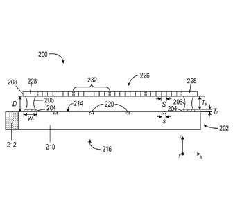
[0029] Figure 2A illustrates an isometric view of an example multiview
display
200. Figure 2B illustrates a cross-sectional view of the multiview display 200
along a
line I-I in Figure 2A. Figure 2C illustrates an exploded isometric view of the
multiview
display 200. As illustrated in Figures 2A-2C, the multiview display 200
comprises a
CA 03044192 2019-05-16
-6-
multiview backlight 202, a reflective layer 204, a support layer 206, and a
screen 208.
The multiview backlight 202 comprises a plate light guide 210 and a light
source 212
optically coupled to an edge of the plate light guide 210. The plate light
guide 210 is
configured to guide light generated by the light source 212 between a first
surface 214
and a second surface 216 of the plate light guide 210.
[0030] In Figures 2B and 2C, the plate light guide 210 may be a plate
optical
waveguide having substantially planar, parallel first and second surfaces 214,
216. The
first surface 214 of the plate light guide 210 may be configured with a number
of
multibeam elements 220. In Figures 2B and 2C, the reflective layer 204 has a
rectangular
shape with an opening 222. In Figure 2C, the support layer 206 also has a
rectangular
shape with an opening 224. In Figure 2B, the support layer 206 is located on a
surface of
the reflective layer 204. Widths of the straight sections of the reflective
layer 204,
denoted by Wr, are greater than the widths of the straight sections of the
support layer
206. In other embodiments, the width of the straight sections of the
reflective layer 204
may be approximately equal to the widths of the straight sections of the
support layer
206.
100311 In Figures 2A-2C, the screen 208 comprises a light valve array 226
surrounded by a screen border 228. The light valve array 226 comprises
separate and
individually operable light valves 230 that may be selectively switched from
opaque to
transparent. The light valves 230 may be liquid crystal light valves,
electrophoretic light
valves, and light valves based on electrowetting. Each of the light valves 230
may be
separately modulated to display images on the light valve array 226. As
illustrated in
Figure 2B, the screen border 228 is placed on and abuts the support layer 206.
The
support layer 206 and the reflective layer 204 form a reflective support
structure that
separates the screen from the plate light guide 210 by a substantially uniform
distance D.
The support layer 206 may be configured with a thickness, T,, and the
reflective layer 204
may be configured with a thickness, Tr, that combine to separate the screen
208 from the
first surface 214 of the plate light guide 210 by the distance D = Ts + Tr.
The support
layer 206 and the reflective layer 204 may include adhesives that adhere
(affix) the screen
to the plate light guide 210 The openings 222 and 224 in the corresponding
reflective
and support layers 204, 206 create an unobstructed space between the light
valve array
CA 03044192 2019-05-16
-7-
226 of the screen 208 and the multibeam elements 220 of the first surface 214
of the plate
light guide 210. In other words, the openings 222 and 224 are created in order
to not
block or obstruct light diffractively couple out of the plate light guide 210
toward the
light valve array 226.
100321 The plate light guide 210 may comprise any one of a number of
different
optically transparent materials or comprise any of a variety of dielectric
materials
including, but not limited to, one or more of various types of glass, such as
silica glass,
alkali-aluminosilicate glass, borosilicate glass, and substantially optically
transparent
plastics or polymers, such as poly(methyl methaerylate) or acrylic glass, and
polycarbonate. In some embodiments, the plate light guide 210 may include a
cladding
layer on at least a portion of a surface of the plate light guide 210 (not
illustrated) to
facilitate total internal reflection (TIR).
[0033] The light source 212 may comprise one or more optical emitters. An
optical emitter may be a light-emitting diode (LED), a laser, an organic light-
emitting
diode (OLED), a polymer light-emitting diode, a plasma-based optical emitter,
a
fluorescent lamp, an incandescent lamp, and any other source of light. The
light
produced by the light source 212 may be of a particular wavelength (i.e., may
be of a
particular color), or may be over a range of wavelengths (e.g., white light).
In some
embodiments, the light source 212 may include sets of optical emitters in
which each set
of optical emitters produces light of a particular wavelength or a range of
wavelengths
that is different from the wavelength or range of wavelengths produced by the
other sets
of optical emitters. For example, the light source 212 may comprise sets of
optical
emitters in which each set of one or more optical emitters produces one of the
primary
colors (e.g., red, green, and blue).
100341 As illustrated in Figures 2A-2C, the light valve array 226 comprises
separate light valves 230 that may be modulated to display images on the light
valve
array. A multiview pixel comprises an array of two or more light valves. In
Figures 2A-
2C, the light valves of the light valve array 226 are partitioned to create
eight multiview
pixels. Each multiview pixel comprises a 7x7 array of light valves 230. Each
7x7 array
of light valves that forms a multiview pixel is demarcated by a dashed-line
square. For
example, light valve 230 is one of forty-nine (49) light valves of a multiview
pixel 232
CA 03044192 2019-05-16
-8-
demarcated in Figures 2A and 2C. A multiview pixel is a set of light valves
that
represent 'view' pixels in each of a similar number of different views of a
multiview
display. In particular, a multiview pixel may have an individual light valve
corresponding to, or representing, a view pixel in each of the different views
of a
multiview image. In addition, the light valves of the multiview pixel are also
called
'directional pixels' in that each of the light valves is associated with a
predetermined
view direction of one of the different views. Furthermore, according to
various examples
and embodiments, the different view pixels represented by the light valves of
a multiview
pixel may have equivalent or at least substantially similar locations or
coordinates in each
of the different views. For example, a first multiview pixel may have
individual light
valves corresponding to view pixels located at {xi, yil in each of the
different views of a
multiview image, while a second multiview pixel may have individual light
valves
corresponding to view pixels located at {x2, y2} in each of the different
views, and so on.
[0035] In some embodiments, a number of light valves in a multiview pixel
may
be equal to a number of views of the multiview display. For example, a
multiview pixel
may comprise an array of sixty-four (64) light valves that may be used to
create a
multiview display having 64 different views. In another example, a multiview
display
may provide an eight by four array of views (i.e., 32 views) and the multiview
pixel may
include thirty-two (32) light valves (i.e., one for each view). For example,
each different
light valve may have an associated direction (e.g., light beam principal
angular direction)
that corresponds to a different one of the view directions corresponding to
the 64 different
views. In addition, according to some embodiments, a number of the multiview
pixels of
the multiview display may be substantially equal to a number of 'view' pixels
(i.e., pixels
that make up a selected view) in the multiview display views. For example, if
a view
includes six hundred forty by four hundred eighty view pixels (i.e., a 640 x
480 view
resolution), the multiview display may have three hundred seven thousand two
hundred
(307, 200) multiview pixels. In another example, when the views include one
hundred by
one hundred pixels, the multiview display may include a total of ten thousand
(i.e., 100 x
100 = 10,000) multiview pixels.
[0036] According to some embodiments, the multibeam elements 220 may be
arranged in either a one-dimensional (1D) array or two-dimensional (2D) array.
For
CA 03044192 2019-05-16
-9-
example, the multibeam elements 220 may be arranged as a linear 1D array. In
another
example, the multibeam elements 220 may be arranged as a rectangular 2D array
as
illustrated in Figure 2C. In other example, the multibeam elements may be
arranged in a
circular or elliptical 2D array. In other examples, arrays of multibeam
elements (i.e., 1D
or 2D array) may be regular or uniformly spaced multibeam elements. In
particular, an
inter-element distance (e.g., center-to-center distance or spacing) between
the multibeam
elements 220 may be substantially uniform or constant across the array of
multibeam
elements. In still other examples, the inter-element distance between the
multibeam
elements 220 may be varied in one or both of x and y directions.
[0037] As illustrated in Figure 2B, the size of a multibeam element 220,
denoted
by s, is comparable to the size of the light valve 230, denoted by S, of the
light valve
array 226. The 'size' may be, but is not limited to, a length, a width or an
area of a light
valve. For example, the size of a light valve 230 may be a length of the light
valve and
the comparable size of the multibeam element 220 may also be a length of the
multibeam
element 220. In another example, size may refer to an area, such as area of
the
multibeam element 220, comparable to an area of the light valve 230.
[0038] In some embodiments, the size of the multibeam element 220 is
comparable to the size of a light valve such that the size of the multibeam
element is
between about fifty percent (50%) and about two hundred percent (200%) of the
size of
the light valve. For example, the sizes of the multibeam element satisfies the
following
condition:
-2 S < S < 2S (1)
In other examples, the multibeam element size is greater than about sixty
percent (60%)
of the light valve size, or about seventy percent (70%) of the light valve
size, or greater
than about eighty percent (80%) of the light valve size, or greater than about
ninety
percent (90%) of the light valve size, and the multibeam element is less than
about one
hundred eighty percent (180%) of the light valve size, or less than about one
hundred
sixty percent (160%) of the light valve size, or less than about one hundred
forty (140%)
of the light valve size, or less than about one hundred twenty percent (120%)
of the light
valve size. For example, by 'comparable size,' the multibeam element size may
be
CA 03044192 2019-05-16
-10-
between about seventy-five percent (75%) and about one hundred fifty (150%) of
the
light valve size. In another example, the multibeam element 220 may be
comparable in
size to the light valve 230 where the multibeam element size is between about
one
hundred twenty-five percent (125%) and about eighty-five percent (85%) of the
light
valve size. According to some embodiments, the comparable sizes of the
multibeam
element 220 and the light valve 230 may be chosen to reduce, or in some
examples to
minimize, dark zones between views of the multiview display 200, while at the
same time
reducing, or in some examples minimizing, an overlap between views of the
multiview
display 200.
100391 Figure 3 illustrates a cross-sectional view of the multiview display
200 in
which light produced by the light source 212 is input to, or coupled into, the
plate light
guide 210 as light 302. The light 302 is coupled into the plate light guide
210 at a non-
zero propagation angle (e.g., about 30-35 degrees) with respect to the first
and second
surfaces 214, 216 of the plate light guide 210. One or more lenses, prisms,
mirrors or
similar reflectors (e.g., a tilted collimating reflector) (not illustrated)
may be used to
couple light produced by the light source 212 into the plate light guide 210
at the non-
zero propagation angle. The light 302 may be input to the plate light guide
210 as
collimated light. The degree to which the light 302 is collimated is
represented by a
collimation factor denoted by a. The collimation factor defines an angular
spread of light
rays within the collimated light. For example, a collimation factor a may
specify that a
majority of light rays of collimated light 302 is within a particular angular
spread (e.g.,
+/- a degrees about a central or principal angular direction of the collimated
light). The
light rays of the collimated light 302 may have a Gaussian distribution in
terms of angle
and the angular spread may be an angle determined by at one-half of a peak
intensity of
the collimated light.
10040] In Figure 3, the plate light guide 210 guides the light 302
according to TER
at the non-zero propagation angle between the first surface 214 and the second
surface
216 of the plate light guide 210. Figure 4 illustrates trajectories of two
rays of light that
propagate within the plate light guide 210 and are incident on the same point
of a surface
402 (e.g., the first surface 214 or the second surface 216) of the plate light
guide 210.
The surface 402 is a boundary between the plate light guide 210 and air 404,
which has a
CA 03044192 2019-05-16
-11-
lower refractive index than the plate light guide 210. Dot-dash line 406
represents a
normal and a denotes a critical angle with respect to the normal. The angle of
incidence
is measured with respect to the normal. The light incidence on the surface 402
at angles
greater than the critical angle a experiences TIR. For example, because the
light
represented by directional arrow 408 is incident on the surface 402 at an
angle greater
than the critical angle a, the light is internally reflected as represented by
directional
arrow 410. Light incident on the surface 402 at an angle less than the
critical angle a, as
represented by directional arrow 412, is transmitted as represented by
directional arrow
414.
[0041] The reflective layer 204 comprises a reflective material, such as,
but not
limited to, silver or aluminum, located on the first surface 214 of the plate
light guide
210. The reflective layer 204 may be pre-formed and deposited as a film or
reflective
tape around the border of the first surface 214. Alternatively, the reflective
layer 204
may be formed by first depositing the reflective material using chemical or
physical
vapor deposition on the first surface 214 followed by forming the opening 222
using any
one or more of wet etching, ion milling, photolithography, anisotropic
etching, and
plasma etching. The reflective layer 204 reflects light that propagates within
the plate
light guide 210 and is incident on the first surface 214 beneath the
reflective layer 204
back into the plate light guide 210.
[0042] Figure 5 illustrates a cross-sectional view of a portion of the
support layer
206, the reflective layer 204, and the plate light guide 210. Dot-dash line
502 represents
a normal to the first surface 214 of the plate light guide 210. Directional
arrow 504
represents light that is incident on the first surface 214 adjacent to the
reflective layer
204. The reflective layer 204 reflects the light back into the plate light
guide 110 as
represented by directional arrow 506. According to some embodiments, the
reflective
layer 204 may serve as a nearly perfect specular reflector by reflecting light
that is
incident on any portion of the first surface 214 that abuts the reflective
layer 204 back
into the plate light guide 210. The light reflected back into the plate light
guide 210 may
be recycled by TIR from other surfaces of the plate light guide 210.
[0043] The reflective properties of the reflective layer 204 prevents light
incident
on the first surface 214 adjacent to the support layer 206 from leaking into
the support
CA 03044192 2019-05-16
-12-
layer 206. Consider, for example, multiview displays configured as described
above but
without the reflective layer 204. Such multiview displays would have the
support layer
206 placed directly against the first surface 214 of the plate light guide
210. As a result,
at least a portion of light incident on the first surface 214 adjacent to the
support layer
206 leaks into the support layer 206, creating an optical drain into the
support layer 206
through which light is lost.
[0044] Returning to Figure 3, each multibeam element 220 is configured to
couple out a portion of light as coupled-out light into a corresponding
multiview pixel
232. For example, in Figure 3, a portion of the light 302 incident on
multibeam element
220 produces coupled-out light represented by diverging directional arrows 238
that pass
through the light valves of the multiview pixel 232. The plate light guide 210
may
include a reflector (not illustrated) at an end of the plate light guide 210
opposite the edge
along which light is input to the plate light guide 210. The reflector
reflects the light 302
back into the plate light guide 210 to recycle light, as represented by an
arrow 306 in
Figure 3. Recycling light in this manner may increase brightness of the
multiview
backlight 202 (e.g., an intensity of the coupled-out light) by making light
available more
than once.
[0045] In the example illustrated in Figures 2B-2C, the reflective layer
204 of the
multiview display 200 described above is a continuous rectangular-shaped
object placed
on the first surface 214 of the plate light guide 210. In other embodiments, a
reflective
layer of the multiview display 200 may comprise reflective segments disposed
on the first
surface 214 of the plate light guide 210.
[0046] Figure 6A illustrates an exploded isometric view of a display 600
that is
similar to the multiview display 200 but the reflective layer 204 and the
support layer 206
of the multiview display 200 are replaced by a segmented reflective layer 602
and a
segmented support layer 604. As illustrated in Figure 6, the display 600
includes the
multiview backlight 202 and the screen 208 described above with reference to
Figures
2A-2C. The reflective layer 602 comprises straight reflective segments 606-
609. The
support layer 604 comprises straight support segments 610-613. When the
display 600 is
assembled, the reflective segments 606-609 are located near edges of the first
surface 214
and the support segments 610-613 are located on the corresponding reflective
segments
CA 03044192 2019-05-16
-13-
606-609. The segmented reflective layer 602 and the segmented support layer
604 form a
reflective support structure that separates the screen 208 from the plate
light guide 210.
[0047] Figure 6B illustrates an exploded isometric view of a display 620
that is
similar to the multiview display 200 but the reflective layer 204 and the
support layer 206
of the multiview display 200 are replaced by a segmented reflective layer 622
and a
segmented support layer 624. As illustrated in Figure 6B, the display 620
includes the
multiview backlight 202 and the screen 208 described above with reference to
Figures
2A-2C. The reflective layer 622 comprises bent reflective segments 626-629.
The
support layer 624 comprises bent support segments 630-633. When the display
620 is
assembled, the bent reflective segments 626-629 are located near the corners
of the first
surface 214 and the support segments are located on the corresponding bent
reflective
segments 606-609. The segmented reflective layer 622 and the segmented support
layer
624 form a reflective support structure that separates the screen 208 from the
plate light
guide 210.
[0048] In other embodiments, a reflective support structure that separates
the
screen 208 from the plate light guide 210 may be comprised of a reflective
material.
Figure 7 shows a cross-sectional view of an example display 700 that is
similar to the
multiview display 200 except the reflective support structure of the multiview
display 200
(i.e., the reflective layer 204 and the support layer 206) are replaced with a
reflective
support structure 702 that separates the screen 208 from the first surface 214
of the plate
light guide 210 by the distance D. The reflective support structure 702 is
located near the
edges of the first surface 214 of the plate light guide 210. The reflective
support structure
702 may be an adhesive that adheres and affixes the screen 208 to the plate
light guide
210 and also comprises a reflective material, such as silver or aluminum. The
reflective
support structure 702 may have a continuous rectangular shape with an opening
704 the
enables diffractively coupled-out light from the diffraction grating to
propagate
unblocked to the light valve array 226. In other embodiments, the reflective
support
structure 702 may be a segmented reflective support structure with segments
located near
the edges and corners of the first surface 214. The reflective support
structure 702 serves
as a nearly perfect specular reflector by reflecting light that is incident on
any portion of
the first surface 214 that abuts the reflective support structure 702 back
into the plate light
CA 03044192 2019-05-16
-14-
guide 210 in the same manner as the reflective layer 204 described above with
reference
to Figure 5.
[0049] According to various embodiments, the multibeam elements 220 may
comprise any of a number of different structures configured to couple out a
portion of the
light 302. For example, the different structures may include, but are not
limited to,
diffraction gratings, micro-reflective elements, micro-refractive elements, or
various
combinations thereof. According to some embodiments, diffractive features of
the
diffraction grating may comprise one or both of grooves and ridges that are
spaced apart
from one another. The grooves or the ridges may comprise a material of the
plate light
guide 210, e.g., the grooves and ridges may be formed in a surface of the
plate light guide
210. In another example, the grooves or the ridges may be formed from a
material other
than the plate light guide material, e.g., a film or a layer of another
material on a surface
of the plate light guide 210.
[0050] Figure 8A illustrates a cross-sectional view a multibeam element 220
of
the plate light guide 210 configured as a diffraction grating 802 in the first
surface 214 of
the plate light guide 210. The diffraction grating 802 comprises diffractive
features with
spacing between diffractive features represented by d, which is wider than one
or more
wavelengths of the light 302. Consider light of a particular wavelength A
interacting with
the diffraction grating 802. The light is transmitted and scattered in
different directions
by the diffractive features. Waves of the light emerge from the diffraction
grating 802
with different phases. As a result, the waves constructively and destructively
interfere to
create beams of light where the waves constructively interfere. For example,
when the
path difference between the waves of the light emerging from adjacent
diffractive
features is half the wavelength (i.e., 2/2), the waves emerge out of phase and
may be
cancelled through destructive interference. On the other hand, when the path
difference
between the waves emerging from adjacent diffractive features equals the
wavelength
the waves constructively interfere creating light with maximum intensity.
Beams of light
that emerges with maxima intensity from the diffraction grating are
represented by
directional arrows 804 and the diffraction angles at which light emerges from
the
diffraction grating 802 with respect to a normal 806 to the first surface 214
may be
calculated according to the diffraction equation:
CA 03044192 2019-05-16
-15-
Om = (n sin Oi ¨ (2)
where
m is the diffraction order (i.e., m = === , ¨2, ¨1,0,1,2, == =);
n is the refractive index of the plate light guide 210;
Oi is the angle of incidence of light 302 with respect to the normal 806;
and
Om is the diffraction angle with respect to the normal 806 of the m-th beam
of light diffractively coupled out from the plate light guide 210.
[0051] In another example, as illustrated in Figure 8B, the multibeam
element 220
is a diffraction grating 810 located at or adjacent to the second surface 216
of the plate
light guide 210. The multibeam element includes a reflective coating 812 that
fills the
diffractive features of the diffraction grating 810 to create a reflective
diffraction grating.
The reflective coating 812 reflects the diffracted light toward the first
surface 214 to exit
through the first surface 214 as the diffractively coupled-out light 814. The
diffractively
coupled-out light 814 that emerges from the plate light guide 210 along the
first surface
214 is refracted as a result of traveling from the higher refractive index
material of the
plate light guide 210 into the lower refractive index of air, which causes the
diffractively
coupled-out light 814 to spread. The spacing of the diffractive features of
the diffraction
grating 810 may be selected to account for spreading of the light emerging
from the plate
light guide 210.
[0052] In other embodiments (not illustrated), the multibeam elements 220
may
be diffraction gratings located between the first and second surfaces 214, 216
of the plate
light guide 210. Note that, in some embodiments, the principal angular
directions of the
coupled-out light created by the multibeam elements 220 may include an effect
of
refraction due to the coupled-out light exiting the plate light guide 210 into
air.
[0053] In some embodiments, the diffraction gratings of the multibeam
elements
may be uniform diffraction gratings in which the diffractive feature spacing
is
substantially constant or unvarying throughout the diffraction grating. In
other
embodiments, the multibeam elements may be chirped diffraction gratings. The
diffractive feature spacing of a chirped diffraction grating varies across an
extent or
CA 03044192 2019-05-16
-16-
length of the chirped diffraction grating. In some embodiments, a chirped
diffraction
grating may have or exhibit a chirp of the diffractive feature spacing that
varies linearly
with distance. As such, the chirped diffraction grating is a 'linearly
chirped' diffraction
grating. In other embodiments, the chirped diffraction grating may exhibit a
non-linear
chirp of the diffractive feature spacing. Various non-linear chirps may be
used including,
but not limited to, an exponential chirp, a logarithmic chirp or a chirp that
varies in
another, substantially non-uniform or random but still monotonic manner. Non-
monotonic chirps such as, but not limited to, a sinusoidal chirp or a triangle
chirp or
sawtooth chirp, may also be employed. Combinations of any of non-linear chirps
may
also be employed.
[00541 In other embodiments, the multibeam elements 220 may comprise micro-
refractive elements configured to refractively couple out portions of the
light 302 as the
coupled-out light. Figure 9 illustrates a cross-sectional view of the plate
light guide 210
in which a multibeam element 220 comprises a micro-refractive element 902.
According
to various embodiments, the micro-refractive element 902 is configured to
refractively
couple out a portion of the light 302 from the plate light guide 210 as the
coupled-out
light 904. The micro-refractive element 902 may have various shapes including,
but not
limited to, a semi-spherical shape, a rectangular shape or a prismatic shape
(i.e., a shape
having sloped facets). According to various embodiments, the micro-refractive
element
902 may extend or protrude out of the first surface 214 of the plate light
guide 210, as
illustrated, or may be a cavity or recess in the first surface 214 (not
illustrated). In some
embodiments, the micro-refractive element 902 may comprise a material of the
plate light
guide 210. In other embodiments, the micro-refractive element 902 may comprise
another material adjacent to, and in some examples, in contact with the first
surface 214.
100551 ln other embodiments, the multibeam elements 220 may comprise micro-
reflective elements configured to reflectively couple out portions of the
light 302 as the
coupled-out light. Figure 10A illustrates a cross-sectional view of the plate
light guide
210 in which a multibeam element 220 comprises a prismatic-shaped micro-
reflective
element 1002 located along the second surface 216. Figure 10B illustrates a
cross-
sectional view of the plate light guide 210 in which a multibeam element 220
comprises a
semi-spherical micro-refractive element 1004 located along the second surface
216. The
CA 03044192 2019-05-16
-17-
micro-reflective elements 1002 and 1004 may include, but are not limited to, a
reflector
that employs a reflective material or layer thereof (e.g., a reflective metal)
or a reflector
based on TIR. In other embodiments (not illustrated), the micro-reflective
element may
be located within the plate light guide 210 between the first and second
surfaces 214, 216.
In Figure 10A, the prismatic-shaped micro-reflective element 1002 has
reflective facets
located adjacent to the second surface 216 of the plate light guide 210. The
facets of the
prismatic micro-reflective element 1002 are configured to reflect (i.e.,
reflectively
couple) a portion of the light 302 out of the plate light guide 210. The
facets may be
slanted or tilted (i.e., have a tilt angle) relative to a propagation
direction of the light 302
to reflect the light portion out of plate light guide 210, for example. The
facets may be
formed using a reflective material within the plate light guide 210 (e.g., as
illustrated in
Figure 10A) or may be surfaces of a prismatic cavity in the second surface
216, according
to various embodiments. When a prismatic cavity is employed, either a
refractive index
change at the cavity surfaces may provide reflection (e.g., TIR) or the cavity
surfaces that
form the facets may be coated with a reflective material to provide
reflection, in some
embodiments. In Figure 10B, the semi-spherical micro-reflective element 1004
has a
substantially smooth, curved surface. The surface curvature of the semi-
spherical micro-
reflective element 1004 reflects the portion of the light 302 depending on a
point of
incidence the light 302 makes with the curved surface. The semi-spherical
micro-
reflective element 1004 in Figure 10B may be either a reflective material
within the plate
light guide 210 or a cavity (e.g., a semi-circular cavity) formed in the
second surface 216,
as illustrated in Figure 10B. Note that, in Figures 10A and 10B, the principal
angular
directions of the coupled-out light 1006 and 1008 are refracted due to a
change in
refractive index as the coupled-out light 1006 and 1008 cross the first
surface 214 into air.
100561 Figure 11 illustrates a flow diagram of a method to operate a
multiview
display. In block 1101, light generated by a light source is optically coupled
into a plate
light guide to create light that propagates within the plate light guide, as
described above
with reference to Figures 2A-2C. In block 1102, a portion of the light is
coupled out of
the plate light guide through multibeam elements as described above with
reference to
Figure 3. In block 1103, light that is incident on a portion of the surface
that abuts a
reflective support structure is reflected back into the plate light guide, as
described above
CA 03044192 2019-05-16
-18-
with reference to Figure 5. The reflective support structure is configured to
allow
transmission of the light coupled out light from the multibeam elements. In
block 1104,
the coupled out light is modulated using multiview pixels of a light valve
array located on
the reflective support structure to create an image.
[0057] It is appreciated that the previous description of the disclosed
embodiments is provided to enable any person skilled in the art to make or use
the present
disclosure. Various modifications to these embodiments will be readily
apparent to those
skilled in the art, and the generic principles defined herein may be applied
to other
embodiments without departing from the spirit or scope of the disclosure.
Thus, the
present disclosure is not intended to be limited to the embodiments
illustrated herein but
is to be accorded the widest scope consistent with the principles and novel
features
disclosed herein.