Note: Descriptions are shown in the official language in which they were submitted.
CA 03045383 2019-05-29
WO 2018/100114 1
PCT/EP2017/081077
Method for production and dispensing carbonated beer from beer concentrate.
FIELD OF THE INVENTION
[0001] The present invention is directed to a beer beverage dispensing
appliance for in situ forming
and dispensing a malt based fermented beverage (MBFB) by mixing a carbonated
liquid diluent
with a MBFB concentrate.
BACKGROUND
[0002] In recent years, home dispensing appliances for domestic use, wherein
multiple beverage
components or beverages are added to one another so that consumers can create
at home their
own compositions adapted to their tastes, have become very popular. This trend
also applies to
fermented beverages, such as malt based fermented beverages (MBFB), like beers
of various
flavors and types.
[0003] A further way, on the one end, for reducing the cost of packaging per
unit volume of beer,
and, on the other hand, for offering the consumers a large palette of choice
is to provide
containers filled with MBFB concentrates which can be used alone or admixed
with one another
and diluted with a liquid diluent. The containers can be in the form of
containers as such or as unit
doses such as capsule or a pod. By mixing such MBFB concentrates with a liquid
diluent a desired
beverage can be created in situ and subsequently or simultaneously served. The
addition and
mixing of the liquid diluent to the unit dose is generally carried out in a
dispensing appliance.
[0004] In situ production and subsequent dispensing of a MBFB comprises mixing
an MBFB
concentrate stored in one or several containers to be mixed with a carbonated
diluent, typically
carbonated water or a carbonated base beer characterized by rather neutral
flavors profile. The
carbonated diluent is a liquid comprising CO2 at a concentration above
saturation at room
temperature and atmospheric pressure. It is generally stored or produced in
situ at a pressure
higher than atmospheric pressure, so that the CO2 is dissolved in the liquid
diluent. Upon mixing
the carbonated diluent with the MBFB concentrate in a mixing chamber, a
pressure drop may
cause CO2 to form froth and foam in the mixing chamber before dispensing. The
amount of foam
and froth formed depends on the CO2-concentration, temperature and pressure,
but it depends
also on the composition of the MBFB concentrate the carbonate diluent is mixed
with. For a
dispensing appliance designed for dispensing a variety of MBFB's it is
therefore not possible to
CA 03045383 2019-05-29
WO 2018/100114 2
PCT/EP2017/081077
tune the equipment in plant for forming a desired amount of froth applicable
to all MBFB
varieties. A system "one size fits them all" does not apply here.
[0005] The underlying problem to produce the final beer beverage starting from
a beer concentrate
is to meet as much as possible the specifications assigned to regular not
reconstituted beers such
as bottled beers , canned beers and especially drafted beers. This problem
represents major
challenges especially on the consumers acceptance level such as user
convenience, mouth feel
taste, dispensing rate, foam quality and formation and stability thereof, cost
and maintenance.
[0006] A first challenge is the carbonation of the beer concentrate itself. In
general, carbonation is
particular critical for beer, since for consumer acceptance a reasonable foam
head in proper
dimensions and stability is required. This is only obtainable by the proper
concentration of CO2 in
said beer. Additional technical complexity is that the foam formation and its
stability depends on
the beer formulation and concentration. For example beer foam comprises
polypeptides of
different groups with different relative hydrophobicity. As the hydrophobicity
of the polypeptide
groups increases, so does the stability of the foam.
[0007] In general beer concentrates are difficult to carbonate since the
product may become foamy
after carbonation and therefore difficult to produce and handle especially
upon dispensing which
is extremely undesirable from a consumer point of view. The foaming of the
beer concentrate is
not only a function of the volume of carbon dioxide to be added to obtain the
dispensed final beer
but is also a function of the beer concentrate content and type of final
dispensed beer beverage.
[0008] From the above, it would be desirable to provide an efficient and
effective dispensing
appliance for dispensing MBFB by mixing a carbonated diluent with a variety of
MBFB
concentrates, which is capable of tuning the quality and amount of the foam
produced during
dispensing of a charge of MBFB into a vessel.
[0009] It is equally very important that the level of carbonation be met for a
particular type of beer
and that the required carbonation level must be delivered and maintained
throughout the
dispensing and at the time of dispensing enabling the reconstitution of single
and/or variable
serving volumes of beer comparable to the conditions when dispensing draft
beer.
[0010] Furthermore, with carbonating concentrated beer, difficulty has been
encountered
maintaining the proper carbonation required for the different types of beer in
combination,
especially with the variable serving volumes required by the consumer. As a
result, numerous and
continuous adjustments of the carbonation process and carbonating equipment
are required to
meet a specified carbonation level for the particular beer and for the volume
of serving.
[0011] From a consumer point of view , in general, the presence of carbon
dioxide does make
beer both more palatable (i.e. mouth feel) and visually attractive. Consumers
tend to view a drink
as incomplete unless it has a head, and the specific form of head expected for
a given type of
CA 03045383 2019-05-29
WO 2018/100114 3
PCT/EP2017/081077
beer. For example, Perfect Draft Stella, typically has a foam height about
40mm and foam half life
time is about 70 seconds in unetched glasses. In addition, the dissolved CO2
is responsible for the
flavor. If a beer is not properly saturated the final beer's characteristics
of full taste is lacking or a
feeling of full taste is not observed. Furthermore, a certain level of
carbonation carbon dioxide
has a preserving property, having an effective antimicrobial effect against
moulds and yeasts.
[0012] In addition, there is a need for appliances which operate with
increased carbonation
effectiveness and efficiency, especially for domestic use. Carbonators are
susceptible to
considerable pressure drops smaller than for delivery of CO2 gas in large
volumes of liquids and
need powerful pumps high energy consuming pumps. Some of said carbonators or
carbonation
systems occupy too much space in a household environment in particular the
inline systems
operate with too long fluid lines.
[0013] Furthermore, the appliance needs to remain clean-in-place (CIP] and
which do not leave
remains or waste in said system after operation. This is particularly a
problem if the same
dispense system has to be used for carbonation of different beer concentrate
types.
[0014] DE 1 757 283 describes a method for dispensing a beverage at a desired
serving temperature
using a batch carbonator and whereby the carbonated water is subsequently
cooled. In a
preferred embodiment, a beer concentrate is used as the beverage concentrate.
[0015] Notwithstanding and given the above, a method and appliance for
effectively and efficiently
producing a single or multi variable serve beer from disposable beverage
containers remains
desirable.
[0016] The present invention proposes a solution meeting such objectives.
These and other
objectives of the present invention will be evident when viewed in light of
the drawings, detailed
description, and appended claims.
SUMMARY OF THE INVENTION
[0017] The present invention is directed to an appliance for the production
and dispensing of malt
based fermented beverage, wherein the appliance comprise a malt based
fermented beverage
concentrated inlet (Fig 1 (8)), liquid lines (Fig 1(6)), a water inlet (Fig 1
(1)), a pressurized gas inlet
(Fig 1 (2)), a carbonation unit (Fig 1 (4)) having a water inlet and a
pressurized gas inlet, a mixing
unit (Fig 1 (9)) in which the carbonated water and malt based fermented
beverage concentrate
are mixed further comprising a pressure control unit allowing to control the
pressure on the water
at the water inlet of the carbonation unit. According to one embodiment the
appliance further
comprises gas pressure regulating means for varying the gas at the inlet of
the carbonation unit.
According to another embodiment the pressure of the liquid water is up to 6
bar and the pressure
CA 03045383 2019-05-29
WO 2018/100114 4
PCT/EP2017/081077
of the gas is up to 6 bar. The final constituted beverage has a foam height of
at least 6 mm and
whereby the foam half life is greater than 15 seconds.
[0018] According to one embodiment the present invention is directed to an
appliance whereby the
carbonation unit is capable of generating gaseous bubbles having an average
major dimension
at the carbonated water outlet of the carbonation unit of less than 0,75mm,
preferably less than
0,50 mm, highly preferably between 0,25 and 0,75 mm
According to a further embodiment the present invention is directed to an
appliance whereby
the water contains between 5 and 10g CO2/L at the mixing unit inlet.
According to another embodiment the appliance comprise liquid lines (Fig1 (6))
which connect
the liquid to the inlet of the carbonation unit and liquid line which fluidly
connects the
carbonation unit to the mixing unit and outlet liquid lines to the container.
According to further embodiment the appliance is characterized in that the
carbonation unit is
adapted to the portion-wise carbonation of water.
In yet another embodiment the appliance comprises a cooling unit in which the
water is cooled
before carbonation.
The appliance further comprises a reservoir for gaseous CO2 with communication
that, in the
CO2 -reservoir stored CO2 can be introduced into the water.
In a specific further embodiment the appliance further comprising a sparger
and a static mixer.
According to a further embodiment, a pressure reducing tube downstream of the
mixing
chamber can be used to further control the foaming and carbonation in the
container.
The appliance of the present invention can be used as a domestic appliance
Typically the appliance of the present invention has a volume ratio of
carbonated water to
concentrate is at least 3:1
According to the present invention the preferred carbonation unit is an in
line carbonation unit.
Preferred appliances further comprise a flow rate controller at the liquid
line (6) which connects
to the inlet of the carbonation unit and/or at the liquid line which fluidly
connects the
carbonation unit to the mixing unit.
The appliance of the present invention also allows the carbonated water to be
subsequently
mixed with a multi variable serving concentrate.
In particular, in accordance with the present invention, a carbonation unit
mix and dispense
system is provided for single dose and/or variable serving beer from
concentrated beer at
similar dispense and quality compared to regular not constituted beer with
comparable end
characteristics with respect to foam height and foam stability, bubble size
and/or mouth feel
taste
CA 03045383 2019-05-29
WO 2018/100114 5
PCT/EP2017/081077
[0019] The present invention is, among others, based on the several findings
including the finding
that, especially at relative low flow velocity, a significant proportion of
the CO2 introduced tends
to coalesce into larger CO2 bubbles which in turn impacts the dispense, foam
stability and taste of
the final product. This finding results in a specific architecture for
efficient and effective
integrated carbonation for dispensing high quality reconstituted beer
comparable to not
reconstituted beer by means of carbonation with controlled small bubble size
generation.
[0020] According to another embodiment, the present invention provides for
further optimized
carbonation systems including criticality of adjustment of static mixer and
post carbonation
downstream fluid line specifications including adjustment associated with the
pore size of the
sparger.
DETAILED DESCRIPTION OF THE INVENTION
[0021] The present invention is directed to an appliance for the production
and dispensing of malt
based fermented beverage, wherein the appliance comprise a malt based
fermented beverage
concentrated inlet (Fig 1 (8)), liquid lines (Fig 1(6)), a water inlet (Fig 1
(1)), a pressurized gas inlet
(Fig 1 (2)), a carbonation unit (Fig 1 (4)) having a water inlet and a
pressurized gas inlet, a mixing
unit (Fig 1 (9)) in which the carbonated water and malt based fermented
beverage concentrate
are mixed further comprising a pressure control unit allowing to control the
pressure on the water
at the water inlet of the carbonation unit. According to one embodiment the
appliance further
comprises gas pressure regulating means for varying the gas at the inlet of
the carbonation unit.
According to another embodiment the pressure of the liquid water is up to 6
bar and the pressure
of the gas is up to 6 bar. The final constituted beverage has a foam height of
at least 6 mm and
whereby the foam half life is greater than 15 seconds. Preferred constituted
beverage has a foam
height of at least 10, highly preferred at least 20mm. Said preferred beverage
has a foam half life
greater then 30s highly preferred 60s. In accordance with the purpose of the
invention, as
embodied and broadly described herein, the present invention relates generally
to an appliance
and method for increased dissolving with increased saturation efficiency of
CO2 into the liquid
diluent from a CO2 gas or from gas whereof an essential part is CO2. In a
certain embodiment
present invention concerns enhancing dissolution of CO2 molecules in the
liquid diluent from a
CO2 gas stream. In accordance with the present invention, the dissolving of
CO2 gas in the
aqueous liquids is made by the operation of the carbonation unit. The present
invention provides
for an appliance in accordance with the present invention which allows a
selective and controlled
generation and increase of the dissolution efficiency of gas compounds
especially CO2.
CA 03045383 2019-05-29
WO 2018/100114 6
PCT/EP2017/081077
[0022] The carbonated diluent is a liquid diluent containing an amount of CO2
higher than the
solubility of CO2 in said liquid diluent at room temperature and at
atmospheric pressure. This
means that the carbonated diluent is sparkling with CO2 bubbles at room
temperature and
atmospheric pressure. The liquid diluent is preferably water. Other liquid
diluents, however, can
be used instead of water. In particular, a beer with a rather neutral flavors
profile can be used as
carbonated diluent. A flavored aqueous solution can also be used. For example,
fruity flavors like
cherries, peach, and the like to produce fruity beers. Water has the great
advantage that the
source of carbonated diluent can be a water tap present in all households,
equipped with a
carbonation station.
[0023] In another embodiment, it is provided that the household appliance
comprises a mixing
device in which the carbonated water and beverage concentrate are mixed.
Preferably, the water
and the beverage concentrate of the mixing device are fed separately. In a
further embodiment, it
is provided that the mixing device is disposed after carrying carbonated
water, in particular, a
good mixing of the carbonated water and the beverage concentrate.
[0024] In accordance with another embodiment of the present invention, a
household appliance is
provided for portioned carbonation and/or flavoring of water, i.e. for
producing a carbonated
post-mix beverage before, wherein the domestic appliance is a water supply, a
carbonation unit
for the carbonation of a diluent and a container holder for holding a MBFB
concentrate container,
wherein the container housing has an opening mechanism for the beverage
container with a
sealing means.
[0025] The diluent is preferably water. In this case, the water supply has in
one embodiment a water
tank from a user's particular refillable. Preferably, the water tank from the
appliance is
removable. In another variant, it is provided that the water supply has a
fresh water connection
which can be connected to a fresh water line and in particular to a household
faucet.
[0026] Typically the carbonation unit includes a continuous mixer with a
connection for the water, a
connection for the gaseous CO2 and an extraction port for carbonated water.
Further, a
differential pressure controller for controlling the gas pressure is provided
as a function of the
water pressure, so that the pressure difference between the supplied water and
the supplied CO2
is substantially constant. A flow regulator to keep constant the flow rate of
the water largely
independent of pressure fluctuations is also provided in one embodiment.
Preferably, the flow
regulator is arranged such that it holds the dispensing amount per unit time
constant. Particularly
preferably the flow regulator is adjustable so that a desired dispensing
quantity per unit time is
user adjustable.
[0027] The present invention is, among others, based on the several findings
including the finding
that, especially at relative low flow velocity, a significant proportion of
the CO2 introduced tends
CA 03045383 2019-05-29
WO 2018/100114 7
PCT/EP2017/081077
to coalesce into larger CO2 bubbles which in turn impacts the dispense, foam
formation, foam
stability and taste of the final reconstituted beer. According to another
finding of the present
invention, small CO2 bubbles are produced and maintained up to the mixing with
the beer
concentrate when the bulk concentration of CO2 is equal or almost equal to the
equilibrium
concentration of CO2. In accordance with the present invention, this is
achieved by introducing
the CO2 as small bubbles via for example sparger (Fig 2) and distributing said
bubbles equally
through the water via mixing. This finding results in a specific architecture
for efficient and
effective integrated carbonation for dispensing high quality reconstituted
beer comparable to
draft beer by means of a carbonation unit capable of generating gaseous
bubbles having a major
dimension at the carbonated water outlet of the carbonation unit between 0,25
and 0,75 mm. By
"major" is meant that at least 50% of the bubbles having said dimension. By
"average" is meant
the number average. The bubbles may have a spherical shape or similar such as
elipsoidic shape.
The major dimension of the fine bubbles should be understood to be a straight
line in-between
the two points on the bubble surface which is furthest apart. Bubble size
distribution (BSD) was
studied with respect to the influence of sparger design and process parameters
on the BSD in the
sparger region of the carbonator Chemical Engineering Science Volume 57, Issue
1, January 2002,
Pages 197-205. Measurements re BSD are generally known in the art and is
described in Chemical
Engineering Science Volume 47, Issue 5, April 1992, Pages 1079-1089
[0028] In accordance with various embodiments, the CO2 gas fluid (Fig 1 (2))
and liquid diluent (Fig 1
(1)) can be combined in a line or fluid conduit (e.g. tube or fluid line) and
flow through a zone of
reduced pressure. Via an inlet port the CO2 gas fluid is aspirated in the
confined environment of
the flow. The CO2 gas can be released from a commercially available
pressurized CO2 gas storage
container or carbon dioxide storage systems or it can be sucked through the
inlet port into a zone
of the liquid fluid line or fluid conduit (e.g. tube or fluid line) which has
a narrower inner diameter
than upstream or downstream of the narrower passage so that if operational the
liquid in this
constricted section of the liquid fluid line or fluid conduit (e.g. tube or
fluid line ) will induce a
pressure drop in the zones compared to directly upstream or downstream or even
near vacuum
creation that is compensated by aspiration of the CO2 gas fluid through a gas
inlet port.
[0029] Preferably, the CO2 gas is released through a porous device as vapor
bubbles before or in
front near or about the zone of the liquid fluid line or fluid conduit (e.g.
tube or fluid line ) which
has a narrower inner diameter than upstream or downstream of the narrower
passage or
alternatively before or in front near or about the zone in the liquid fluid
line or fluid conduit (e.g.
tube or fluid line ) which is separated by an in line entrance shield or wall
and an outlet shield or
wall which comprises openings that are smaller than the inner diameter of the
liquid fluid line or
fluid conduit (e.g. tube or fluid line ). The CO2 gas fluid and liquid fluid
is mixed.
CA 03045383 2019-05-29
WO 2018/100114 8
PCT/EP2017/081077
[0030] According to the present invention, carbonation units which spray the
water into a CO2 rich
atmosphere by jetting through slots are preferred carbonator of the present
invention.
[0031] If needed, post carbonation steps such as further breaking up bubbles
by means of shear
force could be used prior to mixing with the concentrate.
[0032] According to a specific embodiment , the present invention relates to a
process for the
production of malt based carbonated beverage in which water is carbonated at
levels between 2
and lOg CO2/1_ with an in line carbonation step and whereby the carbonated
water is
subsequently mixed with beer beverage concentrate.
[0033] According to another embodiment, an appliance for the production and
dispensing of malt
based beer carbonated beverage is provided whereby the appliance comprise a
concentrate
beverage inlet, a diluent inlet, a pressurized gas inlet, an in line
carbonation unit having a diluent
inlet and a pressurized gas inlet, a mixing unit in which the carbonated water
and beverage
concentrate are mixed.
[0034] According to a sub embodiment, an appliance is provided whereby the one
or more of a beer
concentrate is packaged in a multi variable serving beverage container.
[0035] According to a further sub embodiment, the carbonation unit is adapted
to the portion-wise
carbonation of water.
[0036] According to yet another embodiment, the appliance further comprises a
cooling unit in
which the diluent is cooled before carbonation. A non-limiting embodiment of
the present
invention will be described by way of example with reference to the
accompanying drawings, in
which:
BRIEF DESCRIPTION OF THE FIGURES
[0037] For a fuller understanding of the nature of the present invention,
reference is made to the
following detailed description taken in conjunction with the accompanying
drawings in which:
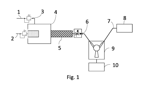
[0038] Figure 1 shows schematically, the carbonation unit integrated in the
appliance in accordance
with the teachings of the present invention;
[0039] Figure 2 shows a schematic side view of an example of a carbonation
unit
[0040] Figure 3 shows the saturation concentration of CO2 in water and ethanol
depending on
pressure at 298 K.
[0041] Figure 4. Shows schematic view of the dispensing appliance according to
the present
invention
[0042] According to one embodiment (Fig 1), the appliance comprises a i) malt
based fermented
beverage concentrate inlet (8), ii) a diluent inlet (2), iii) a pressurized
gas inlet (1) and iv) a
CA 03045383 2019-05-29
WO 2018/100114 9
PCT/EP2017/081077
carbonation unit (4) located along main fluid line (6) and adding carbon
dioxide to the water
flowing along the main fluid line (6).
[0043] According to another embodiment, the appliance further comprising a
cooling unit whereby
the cooling unit is located along main fluid line (6) to cool the water
flowing along a first portion
(up to inlet carbonation unit) of main fluid line (6), and to add carbon
dioxide to the water flowing
along a second portion of main fluid line (6) Fig 1.
[0044] From Fig 1 the appliance comprises a fluid line (7) connected to a
supply source to receive a
concentrated beer (8) and a metering valve (9) connected to main fluid line
(6) to receive the
carbonated water and designed to permit controlled outflow of water from main
fluid line into a
serving container positioned beneath metering valve.
[0045] In Figure 1, a dispensing appliance according to the present invention
is used as follows. A
container (8) contains a malt based fermented beverage (MBFB) concentrate and
is in fluid
communication with a mixing chamber (9). A source (6) of carbonated diluent is
in fluid
communication with the same mixing chamber. After mixing the MBFB-concentrate
with the
carbonated beverage, the thus produced MBFB is dispensed out of an outlet of
the mixing
chamber (9), through a dispensing tube into a vessel (10) i.e. a glass.
[0046] From Figure 4, the solubility of CO2 in water increases very steeply
with increasing pressure
(dashed curve) with about 0.1 to 0.2 mol.% CO2 at 2.5 bar. CO2 has a higher
solubility in pure
ethanol (Et0H) (= solid curve) with about 1.6 mol.% at the same pressure of
2.5 bar. Any aqueous
diluent comprising ethanol would yield a CO2 solubility comprised between
these two curves. The
curves of Figure 4 show that any variation of pressure in a carbonated diluent
may result in CO2
bubbling or dissolving. This is particularly true for water as liquid diluent,
because the straight
dashed line in Figure 4 has a very steep slope. This is critical with MBFB's
because unlike sodas,
once formed foam remains a long time.
[0047] According to one embodiment, cooling and carbonation device
substantially comprises an in-
line cooling unit and an in-line carbonation unit fluid line to respectively
cool and add carbon
dioxide to the water flowing along main fluid line (6).
[0048] More specifically, in-line cooling unit (3) is preferably located along
main fluid line upstream
from in-line carbonation unit (4), so as to cool the water along a first
portion of main fluid line
before the carbon dioxide is added.
[0049] In the Figure 1, the in-line cooling unit comprises an inlet connected
to the supply source by a
portion of fluid line to receive water typically at ambient temperature; and
an outlet supplying
water at a predetermined cooled temperature.
CA 03045383 2019-05-29
WO 2018/100114 10
PCT/EP2017/081077
[0050] The in-line carbonation unit is located along main fluid line (6) Fig
1., between in-line cooling
unit and metering valve and provides for adding carbon dioxide to the water
flowing along the
second portion of main fluid line (6) Fig 1.
[0051] The in-line carbonation unit (4) receives both cooled water at a given
pressure from in-line
cooling unit and carbon dioxide at a given pressure, and appropriately mixes
the two, i.e. water
and carbon dioxide, to supply metering valve with cool sparkling water.
[0052] More specifically, in-line carbonation unit comprises the second
portion of main fluid line (6)
Fig 1., which is defined by, preferably, an elongated tubular body in turn
comprising an inlet
connected to outlet of inline cooling unit to receive cooled water, an inlet
connected to a carbon
dioxide source and an outlet connected to and for supplying cool sparkling
water to metering
valve.
[0053] The carbonation unit comprises a mixing portion communicating with the
inlet where
cold/chilled water is introduced. A CO2 line introduces carbonation to the
diluent such as water.
[0054] Water injectors can also be preferably used in order to produce
atomized flow of water
entering the CO2 path to enhance uptake of carbon dioxide into the water.
[0055] In the Figure 2 for example, the carbonation unit has a tubular body
with small inside
volume, i.e. is sized to substantially contain a volume of water measurable in
tens of milliliters,
and preferably equal to 20-30 milliliters, for rapidly mixing the cooled water
and carbon dioxide.
[0056] Preferred carbonator designs are those whereby the radial distance
between the sparger
surface and the internal carbonator wall is kept to a minimal (Fig 2. (ID))
and/or whereby the
length of the static mixture (FIG 2 (5) is increased and/or whereby the
effective area of the
sparger is reduced all thereby reducing the bubble coalescence formation
within the carbonator.
[0057] In another possible embodiment the tubular body may house a perforated
tubular
membrane or liner, over which water flows on the inside, and pressurized
carbon dioxide on the
outside. More specifically, water flows longitudinally through the perforated
liner, which has a
number of transverse holes designed to only let carbon dioxide through to the
water, while at the
same time preventing outflow of water from the liner. In this way, the carbon
dioxide comes into
contact with the water at a number of points to rapidly carbonate the water.
In accordance with
the appliance as defined within the present invention, it is clear that the
user can select the
desired carbonation level whereby the output is not influenced by the residual
carbonated water
in the carbonator from the previous dispense unlike batch carbonators. In
batch carbonators, the
carbonation level varies with residence time depending on the pressure of the
gas head space
inside the carbonator.
CA 03045383 2019-05-29
WO 2018/100114 11
PCT/EP2017/081077
[0058] In a preferred embodiment of the appliance described above, fluid line
(6) Fig 1. may further
comprise a static mixture (Fig 1 (5)) post carbonation. The length of the
static mixer post
carbonation is sufficient such to avoid coalescence of the gas bubbles.
[0059] In accordance with the present invention, the in-line process of the
water to be carbonated is
carbonized during a conveying operation, that is, the water is with CO2
enriched while being
pumped.
[0060] According to the present invention, the appliance further comprises
flow adapting means,
which, on command, regulate the pressure of the cooled water and/or carbon
dioxide to adjust
the percentage of carbon dioxide added to the cooled water.
[0061] More specifically, flow adapting means may, for example, comprise a non-
return valve
interposed between outlet of in-line cooling unit and inlet of in-line
carbonation unit to prevent
carbon dioxide flow to in-line cooling unit in the event the carbon dioxide
pressure exceeds the
water pressure; and/or a pressurized-water supply pump interposed between
outlet and to adjust
the pressure of the water supply to in-line carbonation unit on command;
and/or a flow
regulating device interposed between carbon dioxide source and inlet of in-
line carbonation unit
to regulate the pressure of the carbon dioxide supply to inlet lib on command.
[0062] The flow adapting means are controlled by an electric control unit
connected to a setting
device , which may preferably, though not necessarily, be located at metering
valve to allow the
user to adjust the carbon dioxide level in the cool water for dispensing.
[0063] More specifically, the appliance may be designed to set two or more
carbon dioxide levels
ranging between a minimum to a maximum level of carbon dioxide, corresponding
to a
predetermined maximum value.
[0064] An electric control unit receives the set level, and controls flow
adapting means accordingly.
Flow regulating device may obviously be replaced with an on-off valve or any
similar device
designed to cut off source from inlet of in-line carbonation unit on command.
[0065] If the user selects an intermediate carbon dioxide level, electric
control unit controls the flow
regulating device to adjust the pressure of the carbon dioxide supply to the
inlet of the in-line
carbonation unit accordingly.
[0066] The supply source provides for continuously supplying the liquid
diluent such as water or any
other beverage at above atmospheric pressure - normally at about 2-bar
pressure ¨ and may
comprise a drinking water circuit of the premises in which the appliance is
installed for example
via filtered tap water supplied by a diaphragm pump. More preferably, the
water supply source
may be connected to the main fluid line via an on-off valve for isolating
supply source from main
fluid line on command.
CA 03045383 2019-05-29
WO 2018/100114 12
PCT/EP2017/081077
[0067] Filters can be used to treat the water coming out of the tap if the
quality is not satisfactory. If
a carbonated diluent other than carbonated water is used, it can be stored in
a vessel.
[0068] Alternatively the appliance may comprise a water tanks such as those by
known dispensers.
[0069] Carbon dioxide source, on the other hand, may comprise a cylinder
containing high-pressure
carbon dioxide, and for supplying carbon dioxide at a predetermined bar,
pressure via a pressure
reducer.
[0070] Operation of the appliance follows that upon the user selecting a given
carbon dioxide level
and activated metering valve, the electric control unit controls the flow
regulating device to
supply the inlet of the in-line carbonation unit with carbon dioxide at a
given pressure, and, at the
same time, activates on-off valve to allow water to flow along the first
portion of main fluid line,
i.e. cooling fluid line, where it is cooled by, preferably, a inline cooling
unit.
[0071] The cooled water then flows along the second portion of main fluid line
i.e. through tubular
body of in-line carbonation unit, where it is gradually mixed with carbon
dioxide. The carbonated
water then flows along the end portion of main fluid line to metering valve by
which it is
dispensed into the container.
[0072] In accordance with the specific architecture of the present invention,
the appliance of the
present invention further prevents, by eliminating the tanks, and the very
small water containing
capacity of in- with the present invention, line cooling unit (Fig 1 (3)) and
in-line carbonation unit
Fig 1 (4) - measurable in tens of milliliters ¨ the possibility of mould or
bacteria forming in the
dispenser, with obvious advantages in terms of user health and hygiene.
[0073] In addition, the appliance provides a continuous, fast supply of cooled
water with a carbon
dioxide percentage varying as required by the user. The user, in fact, can opt
to dispense cooled
water containing one of a predetermined range of carbon dioxide levels.
[0074] When a single container (8) containing an MBFB concentrate is
illustrated in Figure 1, more
than one container can be used, each containing different components in a
concentrated form.
One container can also comprise several chambers, each containing
corresponding concentrated
components. The present invention is not restricted to the number and forms of
the containers.
The MBFB concentrate is in a liquid form (or pasty) so that it can flow under
pressure from the
container into the mixing chamber. The MBFB concentrate may comprise solid
particles, but they
must be in suspension in a liquid medium. A container may contain an amount of
MBFB
concentrate sufficient for a single dispensing operation into one glass
(single dose container) or,
alternatively it may contain an amount of MBFB concentrate sufficient for
several dispensing
operations (= multi-doses container). The latter is more economical in terms
of packaging cost per
unit volume of MBFB concentrate.
CA 03045383 2019-05-29
WO 2018/100114 13
PCT/EP2017/081077
[0075] The MBFB concentrate contained in the container Fig 1 (8)/Fig 3 (8) can
be obtained by
producing a fermented beverage in a traditional manner (e.g., for a beer, by
brewing it in any
fashion known in the art), followed by concentrating the thus produced
fermented beverage.
Concentration occurs by removing, on the one hand, a fraction of the water
contained therein
and, on the other hand, a fraction of the ethanol contained therein. A
substantial amount of both
water and ethanol can be removed from the beverage by filtration, micro-
filtration, ultra-
filtration, or nano-filtration, using appropriate membranes well-known to a
person skilled in the
art.
[0076] The flow of MBFB concentrate into the mixing chamber can be driven by
gravity only, and
controlled by means of a valve but this embodiment is not preferred because it
would impose the
flow of carbonated diluent to be driven by gravity too, in order to not
creating sharp pressure
drops at the level of the diluent opening into the mixing chamber. It is
therefore preferred to
drive the flow of MBFB concentrate either with a pump (not shown) or by
pressurizing the interior
of the container Fig 3 (8) by means of a source of pressurized gas Fig 3 (11),
preferably of
pressurized CO2. The pressurized gas can be stored in a pressure canister. The
gas can be
pressurized with a pump. Alternatively, if available, a pressurized gas can be
available from a
network. It is important to be able to control the volume ratio of MBFB
concentrate and
carbonated diluent fed into the mixing chamber. For this reason, a valve can
be provided to
control the flow rate of MBFB concentrate and carbonated diluent.
Alternatively a volumetric flow
controller such as a volumetric pump can be used for controlling the volumes
of MBFB
concentrate and carbonated diluent fed into the mixing chamber.
[0077] For the purposes of the present invention, the term "beer" includes but
is not limited to a
particular subset of beverages defined as a "beer" under a particular state's
laws, regulations, or
standards. For example, the German Reinheitsgebot states that a beverage
having ingredients
other than water, barley-malt, and hops cannot be considered a "beer"¨ but for
the purposes of
the present invention, the term "beer" has no such ingredient restrictions.
Similarly, for the
purposes of the present invention, the term "beer" does not import or imply a
restriction on the
alcoholic content of a beverage. The present invention both apply to alcoholic
and non alcoholic
beer beverages. As used herein, the term "concentrate" is given the definition
of Oxford
dictionary: "A substance made by removing or reducing the diluting agent; a
concentrated form of
something" (cf.
http://www.oxforddictionaries.com/definition/english/concentrate). In line
with
this, the term "beer concentrate" or, alternatively "(concentrated) beer base"
or "beer syrup", is
meant to relate to beer, respectively which had the majority of its solvent
component ¨ i.e. water
- removed, while retaining most of the dissolved components conferring such
features as taste,
smell, color, mouthfeel etc.
CA 03045383 2019-05-29
WO 2018/100114 14
PCT/EP2017/081077
[0078] As those of skill in the art will recognize, the concentrated beverage
produced by and for use
in various embodiments of the present invention can be produced by a number of
different
processes, including nanofiltration, ultrafiltration, microfiltration, reverse
osmosis, distillation,
fractionation, carbon filtration, or frame filtration. The concentration
process(es) can be
performed with a semi-permeable membrane composed of one or more materials
selected from
the group consisting of cellulose acetate, polysulfone, polyamide,
polypropylene, polylactide,
polyethylene terephthalate, zeolites, aluminum, and ceramics. Concentration
steps may involve
any of the variety of techniques recognized in the art, which allow partial or
substantial
separation of water from the beer and thus retention of most of the dissolved
therein
components in a lower than initial volume. Many of the techniques currently
used within the
beverage industry rely on the so called membrane technologies, which provide a
cheaper
alternative to conventional heat-treatment processes and involve separation of
substances into
two fractions with the help of a semipermeable membrane. The faction
comprising particles
smaller than the membrane pore size passes through the membrane and, as used
herein is
referred to as "permeate" or "filtrate". Everything else retained on the feed
side of the
membrane as used herein is referred to as "retentate". As used herein the term
"concentration
factor" shall be understood as the ratio of the beer volume subjected to step
A) to the volume of
the obtained retentate at the end of the step A), i.e. the ratio of the feed
volume to the volume
of the retentate obtained in the step A) of the method of the present
invention. In an particularly
preferred embodiment, a method in accordance with the previous embodiments is
provided,
wherein the retentate obtained in step A) is characterized by concentration
factor of 3 or higher,
preferably 5 or higher, more preferably 10 or higher, most preferably 15 or
higher.
[0079] The processes utilized to produce the concentrated beverage of the
present invention can
involve one or more concentration steps. In certain embodiments, for example,
the beverage may
be subjected to a first concentration step (for example, nanofiltration) to
obtain a primary beer
concentrate (the retentate) and a permeate. The retentate is composed of
solids such as
carbohydrates, proteins, and divalent and multivalent salts, and the permeate
is made up of
water, alcohol, and volatile flavor components. The permeate can then be
subjected to one or
more further concentration steps (for example, distillation or reverse
osmosis) to obtain a
permeate enriched in alcohol and other volatile flavor components, such as
aromas. The
retentate from the original step can then be combined with this concentrated
permeate to
produce a concentrated beer to be packaged in accordance with the methods and
devices of the
present invention. In certain embodiments of the invention, the resulting
concentrated beverage
has a sugar content of between about 30 degrees Brix and about 80 degrees
Brix, and in further
embodiments, a sugar content of between about 50 degrees Brix and about 70
degrees Brix. In
CA 03045383 2019-05-29
WO 2018/100114 15
PCT/EP2017/081077
other embodiments of the invention, the concentrated base liquid has a sugar
content of
between 10 and between 30 degrees Brix. In these embodiments, the concentrated
beverage may
have an alcohol content of between about 2 ABV to about 12 ABV, between about
10 ABV to
about 14 ABV, or between about 50 ABV to about 70 ABV.
[0080] In preferred embodiments of the invention, to produce one or more
variable servings of a
beverage from the concentrated beer beverage, the container is unsealed (by
puncturing the
metal cap on the container or by other techniques well-known to those skilled
in the art) to
produce variable multi serving of the final resulting beer beverage.
[0081] The beer container can be in the form of a can, bag, cup or box having
a single compartment
or having a first compartment and a second compartment therein. Also
preferably, the bag, cup
or box is formed of aluminium, plastic, glass, and/or metal foil. Moreover,
the first compartment
and the second compartment can each include an opening mechanism such that the
first
compartment and the second compartment are simultaneously opened in the
dispensing
apparatus or prior to insertion into the dispensing apparatus in one or more
locations by piercing,
tearing, or removal of a lid portion from each of the first compartment and
the second
compartment. In addition, the beverage container includes a third compartment
operable to
contain an additional beverage concentrate or other desirable ingredient.
[0082] In certain exemplary embodiments of the invention, water added to the
concentrated
beverage to produce a beverage suitable for consumption is hyper carbonated
water.
[0083] In some preferred embodiments, the concentrated beverage is a
concentrated high-gravity
beer to which water is added, which dilutes the beer and produces a beverage.
In these
embodiments, the addition of water results in a beer having a sugar content of
about 1 degrees
Brix to about 30 degrees Brix and an alcohol content of about 2 ABV to about
16 ABV. In an
exemplary embodiment, the resulting beer has a sugar content of between 4 and
7 degrees Brix
and an alcohol content of between 2 ABV and 8 ABV. In another exemplary
embodiment, the
resulting beer has a sugar content of about 17 degrees Brix and an alcohol
content of between 8
ABV and 12 ABV. In various embodiments, the resulting beer has an alcohol
content of between
2-4 ABV, between 4-6 ABV, between 6-8 ABV, between 8-10 ABV, or between 10-12
ABV.
[0084] While the above-described embodiments discuss diluting the concentrated
beverage with
liquid, those of skill in the art will readily recognize that other liquids
besides water can be added
to the concentrated beer beverage to produce a final beer beverage.
[0085] In certain embodiments of the present invention, one or more flavor
ingredients can be
added to the concentrated beverage to produce a final beverage. Examples of
suitable flavor
ingredients include (but are not limited to) a spice flavor, a fruit flavor, a
hop flavor, a malt flavor,
CA 03045383 2019-05-29
WO 2018/100114 16
PCT/EP2017/081077
a nut flavor, a smoke flavor, other suitable flavors (such as a coffee flavor
or a chocolate flavor),
and mixtures of such flavors.
[0086] Moreover, other concentrated ingredients can be added or combined with
the concentrated
beverage to produce a final beverage, including but not limited to other
concentrated beverages.
[0087] These concentrated ingredients can be, for example, solid or liquid
ingredients such as hop
concentrates, fruit concentrates, sweeteners, bittering additives,
concentrated spices, foaming
promoters, concentrated malt-based liquids, concentrated fermented liquids,
concentrated beer,
colorants, flavoring additives, and mixtures thereof. In some cases, the
concentrated ingredients
(for example, concentrated beers) may be alcoholic concentrated ingredients.
[0088] In accordance with the embodiments of the present invention, the
quantity of concentrated
beverage packaged in the container is measured so that multiple serving of a
beverage can be
prepared from the concentrated beverage in the container. In other embodiments
of the present
invention, the concentrated beverage is packaged in a quantity suitable for
producing multiple
servings of a beverage. In some of these embodiments, the multiple servings of
the beverage are
produced in a single mixing step. In other embodiments, the concentrated
beverage can be
repeatedly mixed with liquid to prepare successive single servings of the
beverage.
[0089] In an exemplary embodiment of the present invention, an appliance for
preparing a beverage
from a beer beverage concentrate is provided. The appliance comprises a
receptacle for intake of
at least one container in which the beer beverage concentrates are packaged,
at least one liquid
intake for the intake of water (and equivalent liquids), at least one mixing
element in which the
beer beverage concentrate is mixed with the carbonated water (or other liquid)
to produce a
beverage, and an outlet from which the resulting beer beverage is dispensed.
[0090] By one portion according to the invention is meant an amount that
corresponds to a
domestic quantity of product to be produced beverage. In particular a beverage
serving is an
amount from about 20 ml to about 1000 ml, more preferably about 100 ml to
about 500 ml, even
more preferably about 100 ml to about 300 ml, more preferably about 200 ml.
The serving size of
a beverage can, for example, depend on a selected container size or glass
size. Further, the
serving size of a chosen mixing ratio of water and beverage concentrate may
depend. Particularly
preferably, the serving size of a user can be selected. A portion packaged
beverage concentrate
comprises according to one embodiment of the invention, a beverage concentrate
quantity
sufficient for producing a beverage serving. In another embodiment, a portion-
wise packaged
beverage concentrate comprises a lot of beverage concentrate, which is
sufficient to produce the
largest selectable beverage serving. For example, the largest selectable
beverage serving
approximately correspond to 400 ml beverage. However, should a user a beverage
serving size of
about 200 ml to be selected, is provided in a first embodiment, two servings
are produced by
CA 03045383 2019-05-29
WO 2018/100114 17
PCT/EP2017/081077
means of portions packaged beverage concentrate. In a second embodiment, it is
provided that
by means of portions packaged beverage concentrate to a beverage serving is
produced which
particularly includes a higher concentration of the beverage concentrate. In a
further
embodiment, a portions packaged beverage concentrate on a lot of drink
concentrate that is
sufficient for the preparation of a beverage serving with an average amount,
for example, about
200 ml. preferably, the concentration of the beverage concentrate can be
varied by the portion
size in the finished beverage that is increased or decreased to.
[0091] In one embodiment it is provided that the carbonation by means of an
inline process water
will have a CO 2 content of about 2 g / Ito about 10 g / I, preferably about 4
g / L to about 8 g / I,
more preferably about 4 g / I to about 8 g / I and in particular about 6 g /
I. Preferably, the
beverage concentrate comprises about CO 2 at concentration that is present in
the final finished
product or to be present. This has the advantage that the carbonated water
produced in the
domestic appliance must have not higher CO 2 concentration than is provided in
the finished
beverage. The addition of beverage concentrate thus does not reduce the total
concentration of
CO 2 in the finished beverage.
Examples:
An appliance with an in line carbonation , mix and dispense system (Fig 3) was
developed and
tested resulting in the reconstitution of single and variable serving volumes
of beer from a
concentrated beer at same dispense rate and at similar quality (carbonation,
bubble and foam
characteristics, mouth feel ) compared to not constituted regular beer.
The examples also demonstrate that preferred carbonation unit include in line
carbonation Fig 3
(4) system including a static mixture as the carbonator operates at lower
velocities compared to
commercial in line carbonators.
A diaphragm pump can be used to pressure water feed into the in line
carbonator. In turn, the
dispense rate can be further controlled by the difference of between the gas
pressure and the
water pressure. Water can be carbonated up to 4.4 g L-1 measured after
dispense at atmospheric
pressure. At a dispense rate of 1,1 L /min the carbonation was 4,1g L-1. Water
temperature is
typically at 2 C before carbonation.
Water feed into carbonator was pressurized to 3,6 bar and CO2 supplied at 3,9
bar dispense flow
rate 1,3L/min and carbonation of dispensed beer was 3,0g/L.
Carbonation performance was further improved by increased water pressure, as
long as the CO2
pressure ranged from 0 to 1.2 bar greater than the water pressure.
CA 03045383 2019-05-29
WO 2018/100114 18
PCT/EP2017/081077
The beer concentrate used is a STELLA and LEFFE and is a 3X concentrate from
an airline-
pressurized keg at pressure up to 7 bar. Fluid line (7) Fig 1. used is a 2.5
mm diameter tube.
Fluid line (6) Fig 1. used is a 2.5 mm diameter tube coupled to a second tube
with 8.4 mm
diameter tube. Carbonator (Fig 2) L: 5 cm ; ID 2,0 cm, sparger (3 ¨Komax
sparger: 2,2 cm. Radial
distance between sparger and pipe wall 0.55 cm.
Static mixer (Komac) 1,27 cm diameter and 15,2 cm. Flow rate 1 L/min.
The carbonated water was mixed with the beer concentrate in line in a 2:1
ratio. Pneumatic
airline Y-connections were used with different size diameter for the
carbonated water inlet and
the concentrate. Concentrate was supplied at 0,5 bar.
The reconstituted beer was dispensed at 1,5 L/min- 2 L/min
Protocol:
The following protocol was designed to measure parameters relating to beer
foam and beer
bubbles to compare selected characteristics of reconstituted beer from the
inline carbonation
with commercially available bottled, canned and draft beers, as well as batch-
carbonated
reconstituted beers.
This protocol comprises:
1. Protocol for dispensing beer, detailing Glass type/ Temperature of the
beer and beer
glass/ Surface condition of the glass/ Angle of beer dispense into glass
2. Bubble and foam measurement protocol, comprising Foam height and half-life
measurements and measurement of representative bubble diameter within the foam
and measurement of the bubble diameter and distribution within the beer and
qualitative evaluation of foam creaminess
Protocol for dispensing beer:
In order to eliminate the impact of the glass on key foam and bubble
parameters when cross
comparing different beers, we standardize the glass type for our
investigations
All beer products shall be poured into Perfect Pint Activator Max 200z Beer
glasses. Made
from toughened beer glass and CE marked and formed in a classic conical shape
and 160 mm
in height and has a laser etched bubble nucleation area at the bottom of the
glass.
The temperature of beer glasses at the point of dispense is 15 3 2C
controlled the glass
temperature by submerging beer glasses in a water bath set at 15 2C measured
by a
thermocouple prior to testing
Dispensed beers shall be served chilled, with canned and bottled beers kept in
the fridge prior
to dispense, draft beers served at chilled temperature provided by the
dispense system. In! ine
CA 03045383 2019-05-29
WO 2018/100114 19
PCT/EP2017/081077
and batch-carbonated reconstituted beers served at a target temperature of 2
2C. The
temperature of the dispensed beer shall be measured after video footage has
been taken, at
3 minutes after dispense. All glasses shall be cleaned using a soft sponge and
tap water
before being submerged in the temperature controlled water bath. Immediately
prior to
dispense, the glasses shall be removed from the water bath and dried crudely
by shaking
away excess water.
Standardize beer dispense methods for each type of beer source
For Perfect Draft, the dispense procedure is as detailed on the user's manual.
For bottled and
canned beers, the glass is tilted 452 and pour the bottle/can close the glass
but not touching the
glass. Once the beer level reaches 1/3 of the glass, we shall straighten up
the glass and slowly pour
more beer in until the beer level reaches 1/2 of the glass (7cm from the
bottom). For batch
carbonated beer, the beer dispensing tube shall be positioned vertically
towards the beer glass
while the glass shall be held at 45 degree angle. For in-line carbonated beer,
the dispense nozzle
angle is at approximately 302 to the vertical and initially line up the glass
at 452. Flow is channeled
down the side of the glass. Once the beer level reaches approximately half way
up the glass, the
glass shall be gradually tilted vertically. Draught dispense guide from the
American Brewers
Association can be further found on the website of Beer Advocate via the link
https://www.beeradvocate.com/beer/101/pour/
Protocol for bubble and foam measurement
Beer bubble and foam measurements are analyzed utilizing video and photography
techniques. iDS cameras are used to record videos and pictures of bubbles in
the beer and
foam formed on the surface of the glass. ImageJ software is used to analyze
the videos and
photographs to quantify foam height and half-life, a representative bubble
diameter within
the foam, bubble diameter distribution within the beer. A separate hand-held
camera is be
used to capture visual information of the beer, which is used to support a
qualitative
evaluation of the foam.
Experimental arrangement
A beer glass is placed onto the reference position on the test bench
Two iDS cameras are positioned on the test bench by two tripods, respectively
Camera 1 (color) focuses on the centreline of the beer enabling the monitoring
beer bubbles
rising along the central axis of the beer glass
CA 03045383 2019-05-29
WO 2018/100114 20
PCT/EP2017/081077
Camera 2 (monochrome) focuses on the front surface of the glass to enable
monitoring of the
foam
A ring light is fixed behind the beer glass to provide uniform illumination
A black background behind the ring light enhances contrast
The height of thefoam shall be measured as a function of time by noting the
distance between the
interface of beer/foam and the shadow line indicating the foam/air boundary at
the central axis of
the glass, at 30 second intervals from video footage captured by camera 2
Fitting a logarithmic equation to the height versus time data provides the
foam half-life
Record subsequent foam heights at 30 s, 1.0 minute, 1.5 minutes, 2.0 minutes
and 4.0 after
the first image and calculate the half-life by fitting the data to a
logarithmic decay. A separate,
hand-held camera i s utilized to take photographs of the dispensed beer foam
from the top
of the glass, and from the side, to enable the vvisual evaluation of
creaminess. The creaminess
of the foam based on vvisual appearance on a scale of 1 to 5
Data:
Draft (via Perfect Draft system)
Carbonation level 3,2g L-1 (variation 0,29) measured by CarboQc analyzer.
Average Bubble size 0,3-0,4 mm
Foam (formation, stability, foam height and foam half life)
Creamy and stable for STELLA Perfect Draft STELLA Bottle STELLA Can.
STELLA Perfect Draft 47,3 4,2mm, 71,3 us;
STELLA Bottle 7 1,5mm, 18,7 2,8s;
STELLA Can 9,2 2,7mm, 16 is
Data re Reconstituted STELLA met the results of STELLA Can, STELLA bottled,
STELLA Perfect Draft
resulting in similar carbonation product requirements and foam formation and
quality and bubble
size parameters. Similar conclusion with LEFFE.
In accordance with the various experiments, preferred executions are those
were the radial
distance between the sparger surface and the internal carbonator wall is kept
to a minimal to
increase the annular velocity of the water leading to efficient distribution
of CO2 within the water
and improved dissolution of CO2 and limiting thereby coalescence of the
bubbles within the
carbonator.
In accordance with the various experiments, preferred executions are those
were the length of
the static mixture is increased leading to higher carbonation efficiency by
improved dissolution of
CO2 and limiting thereby coalescence of the bubbles within the carbonator, in
turn smoothing the
flow.
CA 03045383 2019-05-29
WO 2018/100114 21 PCT/EP2017/081077
In accordance with the various experiments, reduction of the effective area of
the sparger was
found beneficial to smoothen the flow rate by reducing less gas and hence,
less coalescence.