Note: Descriptions are shown in the official language in which they were submitted.
CHEMICAL ETCHING OF EMITTER TIPS
Field of the invention
The present invention relates to a capillary tube for electrospray ionisation
(ESI) mass
spectrometry. The invention may also have application to capillary tubes used
in biochemical
sampling and analysis, particularly applications requiring flow in or out of
nozzles and
particularly in applications involving dispersion of samples. However, the
invention may also
have broader application to any purpose where a fine tip capillary is
required. The invention
may have application to a capillary tube with either a singular tip at the
termination of the
capillary bore or a plurality of tips at the termination of each capillary
bore of a multibore
capillary tube, e.g. for electrospray through each tip. The invention also
relates to methods for
preparing such a capillary tube.
Background of the invention
Electrospray ionization (ESI) is a commonly used ionization method for mass
spectrometry (MS) enabling efficient generation of gas phase ions from a
solution containing
the analyte of interest. Typically, a fine tip capillary tube (emitter) is
required for the most
efficient generation of gas phase ions in very low flow rate ESI (often
referred to as micro-ESI
or nano-ESI). The internal diameter, orifice profile and hydrophobic surface
of the emitter has a
direct impact on the performance of the ESI process and therefore must be
controlled. It is
well-known from literature that the electrohydrodynamics at the emitter tip
plays a significant
role in the ionization efficiency of ESI. Currently, fine tip capillary tubes
are achieved by
heating and pulling down a glass capillary tube by which means the tip can be
pulled to a very
small outer diameter with the consequent effect of simultaneously tapering the
inner diameter.
In the field of ESI-MS, a tapered inner diameter results in a propensity for
clogging at the
elution point and thus robustness and ultimate longevity are sacrificed.
US patent application 2016/0217994 to Oleschuk et al discloses a capillary
tube with
plural internal capillary bores, each terminating at a nozzle structure, thus
forming a
micronozzle array at one end of the capillary tube. The micronozzle array is
formed by reliance
1
CA 3045548 2019-06-06
on a non-homogenous structure of the capillary tube using a combination of
silica and
borosilicate glass in a spaced array of tubes and fillers in a preform, before
the preform is
drawn down into the plural internal bore capillary tube. The differential etch
rates of the two
glass materials is relied upon to provide the micronozzle structure at the
termination of each
capillary bore. In order to preserve the inside diameter of the internal
bores, water is passed
through the internal bores while the capillary tube is immersed in the liquid
etchant. The flow
rate of the water was selected to produce negligible widening of the internal
diameter of the
internal bore. Then the etching time is selected to optimise shape and length
of the
micronozzle structure.
The difficulty with Oleschuk is in achieving the desired arrangement and
spatial control
of the two different materials making up the preform. The fabrication and
arrangement of
custom-doped borosilicate is an intricate and expensive process that can lack
reproducibility.
Such a fabrication method has proved to be difficult in practice, wherein the
lack of
reproducibility of the starting preform creates functional differences in the
final plural internal
bore capillary tube.
US patent 7,491,341 (Kelly et al) discloses a method of making a tapered
capillary tube
with a constant inner diameter. An end of the capillary tube is immersed in a
liquid etchant
while water flows through the inner bore. In Kelly, the capillary tube is
etched to completion
below the liquid level, thus defining an annular sharp ring around the inner
bore. Kelly relies
upon the effect of the concave meniscus surrounding the external surface of
the capillary tube
to form the tapering on the outside diameter above the etchant level. Kelly
therefore affords no
control over the geometry of the tapering of the outside diameter. To do so
would require
control over the surface chemistry between the glass surface and etchant
solution, which could
alter the meniscus shape. It is expected that this would be cumbersome and
difficult to control.
The present inventors have recognised that the flow rate of water or other
protective
fluid flowing through the internal bore can be used to effect control over the
etch rate of the end
profile of the capillary tube to obtain a desired tip profile suitable for ESI-
MS and potentially
other sampling and analysis applications.
2
CA 3045548 2019-06-06
An object of the present invention is to provide a method of forming a
capillary tube
and capillary tubes formed thereby with desired emitter tip profiles. An
object of at least a
preferred embodiment of the present invention is to provide a method of
forming a capillary
tube and capillary tubes formed thereby which is capable of maintaining the
inner diameter of
the internal bore while simultaneously tapering the outside diameter to form a
desired profile.
An alternative object of the invention is to provide the public with a useful
choice.
Reference to any prior art in the specification is not an acknowledgment or
suggestion
that this prior art forms part of the common general knowledge in any
jurisdiction or that this
prior art could reasonably be expected to be understood, regarded as relevant,
and/or combined
with other pieces of prior art by a skilled person in the art.
Summary of the invention
In accordance with a first aspect of the present invention, there is provided
a method of
forming a capillary tube for electrospray ionisation (ESI) having at least one
tip with a desired
tip profile, the method comprising:
providing a pre-finished capillary tube of substantially homogenous material,
the
capillary tube having a first end and an internal bore; and
wet-etching the first end of the pre-finished capillary tube in an etchant for
an etch
duration and flowing a protective fluid through the internal bore of the
capillary tube at a flow
rate during the etch duration,
wherein the flow rate and the etch duration are determined to obtain the
desired tip
profile below a liquid level of the etchant.
By submerging the capillary tube in hydrofluoric acid whilst pumping water
through the
centre hole it is possible to etch down the outer diameter of the capillary
tube whilst
maintaining a constant bore diameter. The water creates a concentration
gradient around the
end of the capillary tube which controls the geometry etched. Experiments have
shown that
higher flow rates create wider, convex geometries, while lower flow rates
create narrower,
concave geometries.
3
CA 3045548 2019-06-06
One or both of the flow rate and the etch duration may be predetermined.
Alternatively,
one or both of the flow rate and the etch duration may be determined in real
time by monitoring
tip development during the etching process. When the flow rate and the etch
duration are
predetermined, the method may further include the step of withdrawing the
first end from the
etchant after the etch duration. Alternatively, if the tip development is
monitored then the
withdrawal of the first end from the etchant may occur once the desired tip
profile is reached.
Preferably, the flow rate is selected according to a number of factors:
= The flow rate should be sufficient to protect the inside diameter from
the etchant
and thus to maintain the internal diameter of the internal bore.
= On the other hand, the flow rate will have an effect on the etchant
concentration
gradient extending radially away from the opening of the internal bore. The
greater the flow rate, the greater the diluting effect.
Accordingly, the flow rate should be minimised to negate the effects of
dilution but
sufficient to maintain the internal diameter of the capillary tube.
The volumetric flow rate may be constant for the etch duration or
alternatively, the flow
rate may be variable over the etch duration. Preferably, the flow is
continuous for the whole of
the etch duration. Alternatively, the flow may be discontinuous, pulsed or
intermittent during
the etch duration provided that this does not have a deleterious effect on the
internal diameter.
Preferably, the volumetric flow rate is about 10 nL/min and less than 75
nL/min. The preferred
range of flow rates is about 10-50 nL/min. In a most preferred form of the
invention, the flow
rate is 25 5 nL/min. Lower flow rates and longer etch times generally result
in the desired tip
profile.
The etch duration is preferably in the range of about 10-40 mins, most
preferably about
10-15 minutes.
Each of the above variables of flow rate and etch duration may be determined
empirically by conducting experiments to determine the effect on tip geometry.
4
CA 3045548 2019-06-06
Alternatively one or both of the flow rate and the etch duration is preferably
predetermined by a mathematical model of a system including the etchant, the
etching of the
pre-finished capillary tube and the flow of protective fluid through the
internal bore. The
mathematical model may use Stokes flow for the velocity profile within the
system. The
mathematical model may use advection-diffusion equations for the concentration
of the etchant.
The mathematical model is preferably run a plurality of times, each time with
a different
set of variable inputs to produce a plurality of simulated tip profiles. A
preferred simulated tip
profile is preferably selected from the plurality of simulated tip profiles
generated by running
the mathematical model with a variety of inputs. The method may involve
comparing the
plurality of simulated tip profiles to the desired tip profile to select the
preferred simulated tip
profile.
The variable inputs to the mathematical model may include density, viscosity
and
chemical composition of a protective fluid and the protective fluid selected
for use is based on
the inputs to the preferred simulated tip profile. In other words, the
selected protective fluid
will have density, viscosity and chemical composition corresponding to or
approximating that
of the inputs to the mathematical model in the run that produces the preferred
simulated tip
profile.
Likewise, the inputs to the mathematical model may include flow rate of the
protective
fluid and the determined flow rate is based on the input flow rate to the
preferred simulated tip
profile. The determined etch duration is preferably also based on the
preferred simulated tip
profile.
The desired tip profile may incorporate any of the following geometries:
tapered i.e.
conical, convex cone, concave cone, wells and holes, either as singular
features or in
combinations.
The desired tip profile is preferably a tapered end face of the capillary tube
with the
tapering on the end face providing a gradual reduction in outside diameter of
the end face
towards a sharp annulus at the opening of internal bore. Thus, the desired tip
profile may be a
5
CA 3045548 2019-06-06
conical shape. Some reduction in the outside diameter of the capillary tube
will also occur but
it is the tapered end face which provides the desired tip profile which when
used as an emitter
tip for ESI exhibits desirable performance characteristics. Preferably the
tapered end face
extends at an angle, which is measured from the edge of the internal bore to
the capillary tube
outer diameter, of <10 degrees, relative to a longitudinal axis through the
internal bore.
The desired tip profile is preferably defined by the end face having varying
angles of
inclination relative to the longitudinal axis which generally progress from
higher to lower
angles towards the opening of the emitter tip internal bore. The lowest angle
of inclination of
the end face may be nearest to the opening, save for the annulus. This
decreasing angle may
lead to a concave cone shape at the end face of the emitter tip.
The pre-finished capillary tube may have an inside diameter within the range
of about 4
gm to 50 gm. Preferably, the range of inside diameters is about 4-25 gm. Most
preferably, the
range of inside diameters suitable for nano-ESI-MS is 4-10 gm.
An additional optional step may include heating and drawing down the pre-
finished
capillary tube to a smaller internal diameter. This process would generally
give rise to a tapered
internal diameter e.g. 1-2 gm to suit specific applications.
The resulting emitter tip profile following the wet-etching may have an
annulus with an
inner radius of 0.5 ¨ 25 gm and an outer radius of 5 ¨ 180 gm. Preferably the
inner radius at the
annulus is 2.5 ¨ 12.5 gm and the outer radius is 5 - 80 gm.
The outside diameter of the pre-finished capillary tube can be of any
dimension < 530
gm and preferably matches that of commercially available fused silica
capillary tubing.
Accordingly, the outside diameter is preferably either 150 5 gm or 360 10 gm.
It is noted that
the capillary tube is usually coated in a protective material having a
thickness of between 10-20
Jim. Thus, the overall outside diameter includes this coating of protected
material.
The pre-finished capillary tube may be drawn from a glass preform with a
predetermined internal diameter and outside diameter as is known in the art.
The internal
bore(s) of the glass preform creates the internal bore(s) of the capillary
tube when the preform
6
CA 3045548 2019-06-06
is drawn down. It is also possible to create a capillary tube with a plurality
of internal bores.
This can be created by drilling, stacking, extruding a plurality of spaced
bores in the preform
before drawing down to a pre-finished plural internal bore capillary tube.
Thus, the present
invention relates to the formation of a capillary tube having one tip or
plural emitter tips at the
termination of each internal bore. The flow rate ranges and etch durations
cited above may be
applicable to a capillary tube with a single emitter tip or plural emitter
tips. The flow rate is
suitably determined at the output of a liquid chromatography pump. The flow
rate may be
equally divided between the plural capillary bores.
The substantially homogenous material may include any of the following
including:
= a glass structure such as, natural quartz, fused silica, doped silica,
borosilicate,
sodium silicate, conductive glass
= Bulk metallic glasses
= stainless steel.
The etchant may include any of the following (preferred starting
concentrations as
indicated:
= hydrofluoric based etchants such as hydrofluoric acid (48 wt%) and
ammonium
bifluoride
= nitric acid (70 wt%),
= sulfuric acid (98 wt%)
= hydrochloric acid (35 wt%)
= hydrogen peroxide (30%) and
= combinations of the above.
In some embodiments it is desired to have a long outside taper on the emitter
tip typical
of a heated and pulled emitter tip. In such cases, mechanical grinding may
also be used prior to,
.. or after the wet etching in the fabrication of the emitter tip to generate
an extended taper on the
outer diameter of the capillary tube. In a preferred method, the first end of
the pre-finished
7
CA 3045548 2019-06-06
capillary tube is ground to form a tapered tip, which may have a final outside
diameter 30 - 80
rim. The wet etching is subsequently used to form the final emitter tip
profile.
The protective fluid may include any liquid forming a protective barrier and
diluting the
etchant concentration at the tip as required. Suitable fluids include pure
water, any liquid that
is miscible with water, dichloromethane, hexane, benzene, toluene, nitrogen
gas, and
combinations thereof.
After withdrawal from the etchant, the capillary tube may be subjected to a
quenching
process to quench further etching and clean the tip of debris. The quenching
may involve
immersion of the first end into water or other suitable liquid with a high
flow rate of flushing
water through the internal bore for a quench duration.
Optionally, it is desirable to chemically modify the etched tip by a
hydrophobic group
through a silanization reaction. This makes the tip less wettable by the
solution used during the
electrospray ionization and thus improves emitter tip performance. The
preferred silane
reagents include any linear, branched, cyclic, substituted and non-substituted
phenyl,
substituted and non-substituted phenyl-alkyl, or fluorinated alkyl-silane
reagents with the alkyl
chain containing more than 2 carbons and each silane's silicon covalently
linked to more than
one leaving group such as chloro, methoxyl or ethoxyl. Further control of the
etch time is
desired to achieve optimal surface roughness to impart a super-hydrophobic
surface on the
emitter tip following silanization.
In accordance with a second aspect of the present invention, there is provided
a method
of forming a capillary tube for ESI, the capillary tube having at least one
tip, the method
comprising:
providing a pre-finished capillary tube having a first end, a longitudinal
axis and an
internal bore with an opening at the first end; and
wet-etching the first end of the capillary tube in a liquid etchant and
flowing a
protective fluid through the internal bore of the capillary tube into the
etchant to obtain a
desired emitter tip profile at the at least one emitter tip, the desired
emitter tip profile
8
CA 3045548 2019-06-06
approximating a cone which is defined by a peripheral wall having varying
angles of
inclination relative to the longitudinal axis which generally progress from
higher to lower
angles towards the opening of the internal bore.
As discussed above, the desired emitter tip profile is formed at least in part
by the end
face at the first end of the capillary tube. This end face is in the form
which approximates a
cone and more preferably a concave cone resulting from the progression of
angles of
inclination. In other words, the tip profile may approximate or substantially
conform to the
external surface of a solid of revolution obtained by 3600 rotation of a
nonlinear curve around
the longitudinal axis of the capillary tube.
Where the surface of the solid revolution is obtained by rotation of a non-
linear curve,
the radius of curvature is preferably maximum with respect to the inner
diameter(s) and outer
diameter of the initial glass capillary/fibre. This solid revolution obtained
by rotation of a
nonlinear curve, where the absolute value of the slope of the first tangent at
curve of the glass
nozzle tip should be maximized.
Preferably the cone is centred at the longitudinal axis.
Another descriptor of the cone shape is a right circular cone. The cone may be
truncated where
the internal bore defines a flat point of the cone shape.
Any of the features described above in connection with the first aspect of the
invention
may have application to this aspect of the invention.
In accordance with a third aspect of the present invention, there is provided
a capillary
tube for ESI, the capillary tube having a longitudinal axis, a first end and a
tip at the first end
approximating a cone which is defined by a peripheral wall having varying
angles of
inclination relative to the longitudinal axis which angles generally progress
from higher to
lower angles towards the opening of the internal bore.
Any of the features described above in any of the foregoing aspects of the
invention
may have application to this aspect of the invention.
A further aspect of the invention may related to a method of predetermining
parameters
of the etching method by a mathematical model of a system including the
etchant, the etching
9
CA 3045548 2019-06-06
of the pre-finished capillary tube and the flow of protective fluid through
the internal bore. The
mathematical model may be run a plurality of times, each time with a different
set of variable
inputs to produce a plurality of simulated tip profiles such that a preferred
simulated tip profile
is selected therefrom.
Any of the features described above in any of the foregoing aspects of the
invention
may have application to this aspect of the invention.
The methods and techniques described here may be implemented on one or more
special purpose computing devices as defined below, with the various different
steps and even
sub-steps above performed on the same special purpose computing devices, on
linked special
purpose computing devices or special purpose computing devices linked with a
control system
of the apparatus 10, such as an NC numerical control.
It will be understood that the invention disclosed and defined in this
specification
extends to all alternative combinations of two or more of the individual
features mentioned or
evident from the text or drawings. All of these different combinations
constitute various
alternative aspects of the invention.
Further aspects of the present invention and further embodiments of the
aspects
described in the preceding paragraphs will become apparent from the following
description,
given by way of example and with reference to the accompanying drawings.
Brief description of the drawings
In order that the invention may be more fully understood, one embodiment will
now be
described, by of example, with reference to the figures in which:
Figure 1 is a schematic representation of a method according to a preferred
embodiment
of the present invention;
Figure 2A is a schematic representation of the dilution gradient of the
etchant and the
initial emitter tip profile of the capillary tube;
CA 3045548 2019-06-06
Figure 2B is a schematic representation of the dilution gradient and the final
emitter tip
profile;
Figure 3 is an array of scanning electron micrographs of wet-etched silica
capillary
tubes showing the effect of flow rate and etch duration on the emitter tip
profile;
Figure 4 is a plot displaying the change in outer radius as a function of etch
duration and
volumetric flow rate;
Figure 5 illustrates the effect of etch duration and flow rate on the emitter
tip profile for
capillary tubes etched with 25, 50, and 100 nL/min volumetric flow rate
through the internal
bore;
Figure 6 illustrates the specifications and co-ordinate system used in the
mathematical
model with Figure 6a being the tip and Figure 6(b) being the axisymmetric co-
ordinate system;
Figure 7 illustrates examples of the placement of the shoulder node;
Figure 8 illustrates the FEM mesh at t = 5;
Figure 9 illustrates the capillary tube, concentration and velocity profiles
for t =0 and 5;
Figure 10 is a schematic of the flow profile while etching;
Figure 11 illustrates the effect of varying the flow rate for D = 10;
Figure 12 illustrates the effect of varying the diffusivity for Q = 50;
Figure 13 illustrates etching at the peak due to the capillary tube tip
becoming steep;
Figure 14 illustrates the tip amplitudes for Q =10, 25, 50 and 100, 150 and
200;
Figure 15(a) illustrates the peak r location versus time;
Figure 15(b) illustrates the peak r location versus flow rate;
Figure 16 illustrates the peak and shoulder joining for Q = 5;
11
CA 3045548 2019-06-06
Figure 17 illustrates the effect of varying the buoyancy for Q = 50 at t = 8;
Figure 18 illustrates the capillary tube profiles for rb = 2.5 and 5 after 30
minutes;
Figure 19 illustrates the rpk displacement versus time comparing rb = 2:5 and
no = 5;
Figure 20 illustrates the profile for Q = 25 after a 15 minute etch with (a)
original, (b)
rotated, (c) normalised (d) converted to rim;
Figure 21 illustrates the fibre tip profile for Q = 25 after a 15 minute etch;
Figure 22 illustrates the simulated capillary tip profiles, the left and right
best fit
equations for the capillary tip from the experiments and the predicted radius
after a 10
and 30 minute etch for D = 9 with (a) Q = 25, 10 minutes, (b) Q = 25, 30
minutes, (c) Q
= 50, 10 minutes, (d) Q = 50, 30 minutes, (e) Q = 100, 10 minutes, (0 Q = 100,
30
minutes;
Figure 23 is the experimental data of Noulty and Leaist [1985] and the linear
and non-
linear best fit lines for the concentration dependant diffusivity;
Figure 24 is the average etch rates (nm/s) with the maximum and minimum values
and
the best fit line for (13);
Figure 25 illustrates a concentration profile and the shoulder concentrations
for the three
c = 1, 30minute experiments with (a) the concentration profile at t = 9 for
one
experiment; and (b) the concentrations at the shoulder for the three 30 minute
experiments;
Figure 26 illustrates how the etch rate parameters vary with diffusivity;
Figure 27 is a flowchart of the overall process from the initial modelling to
the
inspection of the etched capillary; and
Figure 28 is a flowchart of the etching process.
12
CA 3045548 2019-06-06
Detailed description of the embodiments
Microstructured glass fibre fabrication processes in photonics include preform
fabrication by either modified chemical vapour deposition (MCVD), extrusion,
staking or
ultrasonic drilling/milling. The preform is then drawn to fibre to create
glass structures with
unique optical properties. Using precision post-processing techniques, these
microstructured
fibres may then be employed in single-bore and multi-bore emitter tips used in
mass
spectrometry
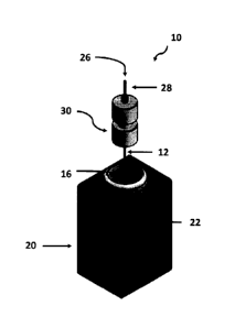
Figure 1 is a schematic representation of apparatus 10 employed in the wet-
chemical
etching method according to the preferred embodiment. The prefinished silica
capillary tube
12 is etched using a wet-chemical etching method schematically illustrated in
Figure 1 using a
solution of HF (48 wt%). The prefinished capillary tube 12 has an outside
diameter of either
150 10 gm or 350 10 gm. The capillary tube 12 has an internal bore with an
inside diameter
of 5 to 11 gm. The capillary tube 12 has a first end 14 (see Figure 2A) which
is immersed into
a solution of hydrofluoric acid (48 wt%). The first end 14 is immersed below
the liquid level
18 of the hydrofluoric acid solution.
The hydrofluoric acid is contained in a plastics tube held within a 3D printed
holder 20
which has a depth viewing window 22 for monitoring the etching progress.
In order to protect the internal bore 13 from the etching effects of the
hydrofluoric acid,
a protective fluid, typically pure water, is pumped through the internal bore
13 towards the first
end 14 where it flows into the hydrofluoric acid solution. The flow of water
in the internal bore
13 is effected by a nanopump 26. The nanopump 26 is connected to the capillary
tube 12 via a
transfer capillary tube 28 and liquid junction 30.
The effect of the water flowing through the internal bore 13 and into the
hydrofluoric
acid solution 16 will protect the internal bore 13 from the etching effects of
the hydrofluoric
.. acid solution 16 due to the low or negligible concentration of hydrofluoric
acid at the opening
34 of the internal bore 13 at the first end 14. This will protect the internal
bore 13 from being
etched by the hydrofluoric acid solution 16.
13
CA 3045548 2019-06-06
The pumping of water through the internal bore 13 will also have the effect of
diluting
the hydrofluoric acid solution 16 according to a dilution profile whereby the
concentration
increases radially and outwardly from the internal bore 13, as depicted by the
arrows directed
upwardly in Figure 2A towards the end surface 32 at the first end 14 of the
capillary tube 12.
The effect of the dilution gradient overtime will lead to differential etch
rates of the end
surface 32, 32' leading to the emitter tip profile illustrated in Figure 2B.
The desired emitter tip
profile for increased performance in mass spectrometry is a emitter tip
approximating a cone
defined by a concave peripheral end wall 32'. A lower flow rate through the
internal bore 13
will reduce the effect of the etchant in the region immediately surrounding
the opening of the
internal bore 13, leading to the pronounced annular sharp ring 36 (see Figure
5) at the opening
of the internal bore 13. It can be seen from Figure 2B that the inclination of
the peripheral end
wall relative to the longitudinal axis of the tube 12 is lowest closer to the
annular sharp ring 36,
compared to the inclination where the surface 32' meets the outside diameter.
As can be seen,
the inclination generally gradually increases radially outwardly from the ring
36, leading to the
concave cone shape as depicted. This emitter tip profile is highly desired for
ESI in mass
spectrometry.
Figure 3 illustrates the effect of etch duration and volumetric flow rate on
the emitter tip
geometry. All capillary tubes were initially 150/7 gm OD/ID. The scale bar in
each image is
gm. The most desirable emitter tip profiles are achieved in the bottom right
hand corner.
20 The most highly desirable emitter tip profiles are those for 25 and 50
nL/min volumetric flow
rates and 15 minutes duration. Volumetric flow rates of 75 nL/min and above
did not produce
acceptable results and it was not considered that extending the etch duration
beyond 15 minutes
would produce improved results.
It can be seen from Figure 3 that the outside diameter of the capillary tube
also
undergoes reduction in the etchant.
Figure 4 is a plot displaying the change in outer radius as a function of etch
duration and
volumetric flow rate. The solid triangles, open squares, and solid circles
refer to 100, 50, and
25 nL/min volumetric flow rates. The change in outer radius generally
increased as a function
14
CA 3045548 2019-06-06
of etch duration and volumetric flow rates. The emitter tip shape and size
(radius) are important
features for the production and performance of the final product.
Figure 5 illustrates the effect of etch duration and flow rate on the emitter
tip profile
for capillary tubes etched with 25 (top), 50 (middle), and 100 (bottom) nL/min
volumetric flow
rate through the internal bore. Etch time increases from the outer profiles
(10 minutes) to the
inner profile (30 minutes) in 5-minute increments. As shown, reducing the
volumetric flow rate
and increasing the time generally increased the sharpness of annular ring 36,
with 30 minutes
producing the best result from those depicted.
The etch duration and the flowrate may be determined empirically.
Alternatively these and
other variables may be determined according to a mathematical model as
explained below. The
overall process including the mathematical model is shown in the flowchart in
Figure 27.
1. Introduction to Mathematical Model
Hydrofluoric acid is a solution of hydrogen fluoride (HF) in water which is
commonly used to
etch and polish glass due to its high reactivity towards SiO2 molecules, where
the chemical
reaction governing the etching of SiO2 by HF is generally regarded to be given
by
SiO2 + 6 HF ¨> H2SiF6 + 2 H20. (1)
In concentrations above 48% by weight the HF spontaneously forms fumes which
decreases the
concentration unpredictably and are highly dangerous to inhale. As a result,
it is common
practise in the etching of SiO2 to use 48% by weight hydrofluoric acid in
order to maximise the
etching properties of the hydrofluoric acid, whilst maintaining predictable
etch rates and safety.
When HF is dissolved in water some of the HF molecules dissociate into highly
mobile H+ and
F ions which, for low concentrations, then bond with the undissociated HF
molecules forming
HF2-. Hence, for low concentration solutions of hydrofluoric acid the
equilibria relations are
given by
HF # F + H+, HF + F # HF2-.
(2)
CA 3045548 2019-06-06
However, for higher concentrations, we find the existence of H2F3- and H3F4-
ions. These
higher polymeric ions are highly reactive to SiO2 however their equilibria
relations are
unknown.
Noulty and Leaist [1985] investigated the diffusivity of aqueous hydrofluoric
acid
experimentally at concentrations of 0.002 to 0.2 % HF by weight - measurements
at stronger
concentrations were unsuccessful due to the formation of bubbles of HF vapour.
They
measured the binary diffusion coefficients of hydrofluoric acid in water and
found for very low
concentrations the binary diffusion coefficient decreased rapidly as the
concentration was
increased up to 0.003% by weight. Increasing the concentration past 0.003% by
weight resulted
in a gradual increase in the binary coefficient as the concentration was
increased. However,
although they showed a slight variation in the diffusion coefficient over a
small concentration
range, it is common in the modelling of etching using hydrofluoric acid to
assume the
diffusivity is constant.
We will use the advection-diffusion equation with Stokes flow and the relation
given in (1) to
calculate a flux condition for the concentration on the fibre surface to model
the etching
process developed by Bachus et al. [2016]. Due to Noulty and Leaist [1985]
showing a
variation in diffusivity with concentration at low concentrations and a lack
of data for the
diffusivity at higher concentrations, the governing equations for our model
will be derived with
a concentration dependant diffusivity. Figure 28 is a flowchart of the
mathematical model.
We will investigate the effects of varying the model parameters and compare
our simulated
results with experiments in order to validate our model and determine whether
a constant
diffusivity is sufficient and, if so, what its value should be.
2 The Mathematical Model
We model the system in axisymmetric cylindrical coordinates r = (r, z), with
the z-axis running
through the centre of the fibre and the r-axis measuring distance outwards
from the centre, both
16
CA 3045548 2019-06-06
in um. We set the fibre bottom to be at z=0 and gravity, g, points vertically
downwards such
that g = (0, -g) and denote the bore radius to be rb and the initial outer
radius to be R. Due to
the viscosity, /.1, of water and HF being very similar, we assume /I = ,UHF
throughout the entire
system. The co-ordinate system used is shown in Figure 6 where the dashed line
in Figure 6b at
r = 0 runs along the centre of the bore and is a line of symmetry. For
convenience, we refer to
the point where the bore wall meets the fibre bottom as the 'peak' and has
coordinates rpk = (rpk,
zpk) and the point where the fibre bottom meets the fibre side as the
'shoulder' and has
coordinates rsh = (rsh, zsh).
2.1 Velocity
We model the flow profile, u = (Ur, us), as Stokes flow with the Boussinesq
approximation for
buoyancy due to the density difference between water and the hydrofluoric
acid. Due to the
density of hydrofluoric acid being greater than that of water, we may express
the density, p =
p(c) where c is the volume fraction of 48% by weight hydrofluoric acid, at any
point as
P = pa ¨ B(c),
(3)
where pa is the density of 48% by weight hydrofluoric acid and B(c) > 0. This
gives us the
mass and momentum conservation equations as
I?' = U = 0,
(4)
Vp =u V 2 u ¨ g B(c), (5)
for pressure, p, and the del operator in cylindrical coordinates, V.
For concentrations of hydrogen fluoride less than 48% by weight, the density
profile is close to
linear in c, hence the density is given by
p = c pa + (1 ¨ c) Pio
(6)
where p, is the density of water. Expressing this in the form given in (3)
gives
B(c) = (1 ¨ c)(p, - põ).
(7)
17
CA 3045548 2019-06-06
The flow rate of the water flowing though the bore is given by Q = QnL/min and
is modelled
as Poiseuille flow moving in the negative z direction with flow profile u =
(0, -ub), where
Ub = 2 Q (rb2 - r2) / or rb4)
for 0 < r <
rb. (8)
2.2 Concentration
We model the concentration using the advection--diffusion model, given in
axisymmetric
cylindrical coordinates by
ac /at = 17 = (D(c) I7c) - u = Vc,
(9)
where D(c) = D(c)nm2/s is the concentration dependant diffusivity. The
chemical reaction
governing the etching of SiO2 by HF is given by (1), hence we have a flux
condition on the
fibre boundary due to etching. In order to avoid having a second concentration
species in our
model we consider the H2SiF6 to have the same properties as water. We can
calculate the molar
flux of HF due to etching, je, as 6 times the number of moles of SiO2 etched,
given by
je = 6 ps ER / Ms, (10)
for the concentration dependant etch rate, ER = ER(c)nmls, and density and
molar mass of
SiO2, A, and Mõ respectively. By multiplying (10) by the molar mass of HF,
MHF, we may
convert the molar flux to the mass flux of HF molecules. By noting that the
mass of HF
molecules is given by 0.48 pa c and as the HF mass flux on the fibre is equal
to the negative of
the HF mass flux due to etching, the fibre boundary condition is given by
D(c) ac / an = -12.5 MHF ps ER / Ms,
(11)
where n = (ii,., nz) is the unit normal vector to the surface pointing away
from the acid.
2.3 Fibre Surface
We denote the location of the fibre surface as rf = !X ri(t), zi(t)). The
equation governing the
fibre surface location is given by
18
CA 3045548 2019-06-06
drf / dt = ER n.
(12)
We use the relation proposed by Fogler et al. [1975] (for molar flux, which we
equate with (10)
and re-arrange) to express the etch rate as
ER = ki c" (1 + k2c)6),
(13)
for k1 = kinm/s and k2 is dimensionless. This dictates that k1 ca dominates at
low
concentrations, where Spierings [1993] has shown that the relationship between
concentration
and etch rate is close to linear and hence we expect a z 1, and k1 k2 c'fl
dominates at high
concentrations.
2.4 Non-Dimensionalisation
We use the scales
r = rb r', u = IQ k2 u', t = rb t' / (k1 k2),
p - itt k1 k2 p7 rby (14)
dimensionless parameters
Bc = -g rb2 (pa - p,õ) / (P kl k2), Uc = 2 Q/ ac kl k2 r b2), Jc = 12.5 MHF ps
/ (Ms pa), (15)
for non-dimensional buoyancy, inlet flow and flux constants, respectively, and
the
dimensionless diffusivity function
D c(c) = D(c) / (k1 k2 r b).
(16)
Dropping the primes for convenience gives the non-dimensional equations as
17 = u = 0,
(17)
17p = 172u + B c (1 - c),
(18)
0c/at= 17 = (Dc(c) 17c) - u = Vc, (19)
drf/dt = c" (1Ik2 + 06 ) n,
(20)
with inlet condition
ub = tic (/ - r2) for 0 < r <1,
(21)
19
CA 3045548 2019-06-06
and subject to
Dc(c) / = -J ca (1/k2 + c1?),
(22)
on the fibre boundary.
3 Numerical Simulation
We let
clyo / dt = (ye" - con) I (JO, (23)
for time step size, At, and any function co = co(t) and solve equations (17)
and (18) and then (19)
in weak form using a finite element method using the software package FEniCS.
We then solve
(20) and move the fibre boundary correspondingly before finally interpolating
the previous
solution onto the new mesh. We then increase the time by At and repeat this
procedure.
The mesh is set up with the bore inlet at z, = min(z) and ri < 1, no slip on
the fibre surface,
symmetry at r = 0 and no diffusive flux at the other boundaries and subject to
the initial
condition
c=0 if r < 1 and z > 0, or
c = 1 otherwise.
(24)
At each time step we move the nodes on the fibre boundary using (20). As the
peak and
shoulder nodes (as defined in Section 2 and shown in Figure 6b) have no normal
vector we
calculate the new position of the edge connecting the corner nodes to their
adjacent nodes using
(20) and place the corner node at the point the new edges intersect. This
process is shown in
Figure 7 for the shoulder node where the crosses represent the node positions
and the solid line
represents the joining edges before etching, the dashed/dotted lines
represents the new positions
of the edges connecting the shoulder node to the node adjacent on the fibre
side/bottom,
respectively, and the asterisk represents the new position of the shoulder
node where the two
new edges intersect. Nodes on the fibre bottom typically etch vertically more
than they etch
CA 3045548 2019-06-06
horizontally, whereas nodes on the fibre side typically etch horizontally more
than they etch
vertically, as can be seen in Figure 7. This results in the corner nodes
getting closer to the
points either side of them and eventually wanting to pass these neighbouring
nodes. As a result,
after the new positions for the nodes on the fibre surface are calculated, we
redistribute them
along the fibre maintaining their original separation ratios. In order to
redistribute the points
more accurately, we solve for a quadratic around each node and move the node
along the curve
found.
In order to avoid mesh distortion, we then redistribute all the other nodes on
the mesh boundary
by calculating the relative movement of the peak and shoulder nodes and
compressing or
stretching the node separation on the fibre boundary as required. Finally, we
use FEniCS inbuilt
automatic re-meshing class to redistribute the internal nodes. Figure 8 shows
an example of the
mesh at t = 5, although we can see there is some compression of the elements
around the peak
and some stretching of the elements around the shoulder, these effects are
significantly reduced
due to the steps described above.
We use (13) with k1 = 7.639, a = 1.000, k2 = 2.475, # = 2.296, as given in
Appendix A for our
etch rate and a fibre diameter of 125)rm with a 101.rm bore diameter. This
gives a maximum
etch rate of ER = 26.548 and hence we will etch through to the bore after
36.098minutes for
.. which t = 8.191. Thus, we will simulate up to t = 8.
Figure 9 shows the solutions at t = 0, after the velocity and concentration
equations have been
solved, but before etching and at t = 5 for Q = 50. The colour of the
background is scaled with
c and its colour bar is shown in the bottom right of the figure, and the
arrows point in the
direction of the flow and are coloured with the magnitude of u and its colour
bar is shown in
the top right of the figure. Note that tic = 1.122 x 10⁶, however scaling the
velocity colour bar
to tic results in all the arrows outside of the bore being blue so we have
limited the scale such
that the difference in velocities throughout the acid is distinguishable.
Further, the blue arrows
pointing normal to the fibre surface may be ignored as they are due to
numerical error
.. producing flow velocities O(10").
21
CA 3045548 2019-06-06
We can see that the concentration of HF near the peak is very low and it
increases as the
distance from the peak is increased until we have close to 48% HF by weight
far away from the
peak. Due to the less concentrated acid being less dense this causes a
buoyancy effect driving
the flow upwards, this results in the 48% HF by weight far away (out of view
in these figures)
being pulled upwards and a flow circulation occurring. Focussing on the
velocity near the peak
we can see that the velocity of the water coming out of the bore is quickly
slowed. By varying
the flow rate we find it has little effect on the velocity profile, hence
varying the flow rate only
affects the quantity of water being added to the acid and hence causes a more
diluted
concentration profile across the fibre bottom. As the fibre etches and a
sharper peak forms, as
in Figure 9b, we find a vortex forms just to the side of the peak and a higher
concentration of
HF along the fibre bottom to that in Figure 9a and hence higher etch rate at
later times. A
schematic of the flow profile is shown in Figure 10.
4 Varying the Parameters
In order to improve our understanding of the etching process we will
investigate the effects of
varying our parameters. As the relation between diffusivity and concentration
is not known, we
will consider a constant value for diffusivity which we will vary and a large
range of flow rates
and investigate how they affect the system. As the fibres have a constant bore
diameter in the
range of 41õun to 10 m we will consider the effects of different bore
diameters. Also, due to the
production of H2SiF6 and H20 as the fibre is etched, a mixing region exists at
the fibre surface
and as a result our calculated etch rate parameters will vary depending on the
diffusivity (the
details of which are given in Appendix B). A summary of the values for all the
parameters and
variables we will consider are given in Table 1.
Parameter Value Units
Pa 1.15x 10³ kg/m3
Pw 1.00 x 10³ kg/m3
ps 2.65 x 10³ kg/m3
MHF 20.01 x 10⁻³
kg/mol
Ms 60.08 x 10⁻³ kg/mol
0.9 mPa = s
rb 2-5
62.5
22
CA 3045548 2019-06-06
7.639 7.692 nm/s
k2 2.475 -> 2.560
a 1.000
6 2.296 2.325
1 4 200 nL/min
1-20 nm 2/s
Table 1: The values of the parameters and variables used.
Figures 11 and 12 show the effects of varying the flow rate and the
diffusivity, respectively.
We can see that the effects of lowering the flow rate are very similar to the
effects of increasing
the diffusivity. This is due to both larger flow rates and lower diffusivity
resulting in smaller
concentration profiles around the fibre tip which cause the fibre to etch into
a convex shape.
Further, we can see that for the higher flow rates (Q > 100) and lower
diffusivity (D < 1) the
flow is able to counteract the diffusion around the bore outlet resulting in c
0 here and hence
we get very little etching at the peak. As the flow is decreased (Q 50) or the
diffusivity is
increased (D 5) the flow in through the bore is no longer able to counteract
the diffusion and
we get a low concentration at the peak which results in it etching upwards.
However, the lower
flow rate/higher diffusivity results in a larger concentration profile around
the fibre and hence
the fibre is etched more and creates a concave profile with, at later times, a
sharp corner at the
peak. The combination of the fibre becoming less wide and the peak becoming
steeper
increases the velocity profile around the peak and as a result a higher
concentration here due to
the increased advection of the water away from the peak. As the peak gets
steeper it leaves only
a thin wall between the bore and the fibre bottom which, coupled with the
increased
concentration here, etches the top of the peak off at an increasing rate
resulting in the vertical
location of the peak to move upwards quicker at later times, as demonstrated
in Figure 13.
As the flow rate is decreased (Q 25) or the diffusivity is increased (D c=-;
20) further these
effects are further magnified - the concentration at the peak is slightly
larger resulting in more
etching here and the lower flow rate dilutes the acid less resulting in a
larger concentration
profile on the tip of the fibre and the fibre is etched more. Finally, as the
flow rate is decreased
(Q 10) or the diffusivity is increased (D> 20) the concentration at the
peak is significantly
larger which, although it results in a larger concentration profile on the tip
of the fibre and
23
CA 3045548 2019-06-06
hence more etching, also results in the peak concentration and shoulder
concentration being
closer together and a much less steep profile is created.
As time is increased and the fibre tips for the lower flow rates and larger
diffusivities become
steeper and narrower, the velocity profile around the fibre peak is increased
causing a larger
concentration here due to the increased advection of the water away from the
peak.
Simultaneously, the narrowing of the fibre brings the shoulder r location
closer to the peak and
hence the concentration here decreases with time. As a result, initially the
tip amplitude
increases as the shoulder etches down more than the peak for all flow rates
and diffusivities,
however if the peak becomes steeper and the peak z location increases faster
(as discussed
above), although the concentration at the shoulder is higher the peak etches
up quicker than the
shoulder and the amplitude begins to decrease. This can be seen in Figure 14
which shows the
tip amplitudes which we define as the shoulder z location minus the peak z
location.
.. Due to the bore not being fully protected by the flow it not only etches
down, but also etches
out. For the higher flow rates and lower diffusivities this effect is very
small, however as the
flow rate decreases or diffusivity increases it becomes more significant due
to the increase in
concentration at the peak, for example Q = 10 in Figure 11b. However, if the
peak then
becomes steep, the higher concentration outside the bore begins to etch the
peak location back
towards its original position. Figure 15 shows the peak r location against
time for different flow
rates in Figure 15a and against flow rate at different times in Figure 15b. We
can see that for
higher flow rates the peak is gradually being etched outwards for the duration
of the simulation
whilst for the lower flow rates, although they initially etch outwards they
begin etching back
inwards. The flow rates that have the largest concentration gradient on the
tip, i.e. those that
produce the steepest tips, are able to etch back inwards the most due to the
larger concentration
difference between the inside and outside of the bore.
For even lower flow rates it is possible for the peak and shoulder to join. An
example is shown
in Figure 16 for Q = 5. We can see the low flow rate has resulted in
significantly more outward
etching of the peak position compared to the examples we examined earlier due
to a higher
24
CA 3045548 2019-06-06
concentration at the peak. As the concentration difference between the peak
and the shoulder is
relatively low we do not get a steep fibre tip and so the peak position does
not begin to etch
back inwards at later times as we saw previously. Eventually, the peak and
shoulder positions
merge which causes our numerical method to fail due to elements becoming
infinitesimal.
However, we would expect the fibre side to continue etching inwards resulting
in the peak-
shoulder point to also move inwards resulting in a final very slender fibre
whose bore opens at
the outlet joining the fibre side.
In order to investigate the effects of varying the buoyancy force we replace
Be with kb B, for a
constant kb> 0. Varying kb corresponds to varying pa - pw, hence deceasing kb
corresponds to
the the densities of HF and water being closer and increasing kb corresponds
to there being a
greater density difference between HF and water. We find that increasing kb
results in more
etching occurring, however the effects are very small, as shown in Figure 17.
The flow profile
in the acid is very weak and is dominated by the buoyancy, however halving or
doubling the
buoyancy force has very little effect on the system as the size of the
buoyancy force is not
important as long as it is large enough to dominate the force of the flow
exiting the bore.
This is further demonstrated by considering changes to rb. Decreasing rb
results in a faster flow
through the bore and hence results in a lower concentration profile at the
peak and less etching
here, however has a very small effect at the shoulder. We can see from Figure
18 that the
general shape of the fibre tips for rb = 2.5pm and rb = 5pm are very similar
and there is no
significant change in the etched fibre width. Figure 19 shows the rflk
displacement for rb =
2.5pm and rb = 5pm. We can see a significant reduction in the outward etching
of the bore
which quickly etches back inwards due to the sharper peaks formed for the
smaller bore
diameter.
Throughout our investigation into the parameters of our system we have found
that the system
is stable for changes to the parameters other than the diffusivity and flow
rate. These
parameters are the only ones which effect the concentration profile which has
a profound
impact on the final etched profile. Higher diffusivity or lower flow rate
creates a stronger
CA 3045548 2019-06-06
concentration profile along the fibre bottom and sharp peaks, however very low
flow rates or
very high diffusivity results in a smaller concentration gradient and less
sharp peaks. Hence, in
order to control the geometry of the fibre tip, the flow rate and diffusivity
must be such that it
creates a concentration profile with both the required strength and gradient.
5 Experimental Data Analysis
Experiments were carried out using fibres with an outer diameter of 120pm to
130pm and
internal diameter of 101AM. The fibres were dipped into 48% by weight
hydrofluoric acid to a
depth of 2cm such that they were perpendicular to the surface and in the
centre of the test tube
and left there for 10, 15, 25, 30 and 32.5 minutes. After the allotted time in
the acid had been
reached the fibres were removed from the acid and dipped into a test tube of
water in order to
wash any remaining acid off the fibre surface. Whilst in the acid, water was
pumped through
the fibre bore with flow rates of 25, 50 and 100 nL/min, where 25nL/min was
found to be the
minimum flow rate possible for which the pump used could provide a consistent
flow due to
the low pressure required at lower flow rates. Each combination of time and
flow rate was
completed in triplicate to demonstrate consistency.
After being etched, pictures of the fibres were taken under an optical
microscope and imported
into ImageJ and (X, Y) coordinates in pixels found for the outline of the
fibre, as shown in
Figure 20a. This data was then rotated until the fibre was straight by finding
the centre of the
fibre at points far away from the fibre bottom and aligning those centre
points. This is shown in
Figure 20b where we find the centre points at Y = 800, 900, 1000 and 1100
align at X = 902.5
when rotated at 0.007radian. This profile is then normalised such that its
centre in X lies on x =
0 and the bore outlet lies at y = 0, as shown in Figure 20c, before finally
being converted from
pixels into pm, as shown in Figure 20d.
By removing points along the fibre side we find the profile of the etched
fibre tip, as shown in
Figure 21a, from which we can see asymmetry in the profile. This is most
likely caused by the
fibre not being perfectly perpendicular to the acid surface and hence one side
of the fibre
bottom being slightly higher than the other. As a result, the buoyancy effects
cause more
26
CA 3045548 2019-06-06
advection on the higher side creating a more dilute concentration profile and
hence less etching
on the higher side. If we rotate the data further we find we are able to find
very symmetric
profiles, however when this angle is used on the full profile it is clear the
fibre is not straight.
Hence, we believe to get the most accurate profile of the fibre tip we must
use the asymmetric
profile and consider each side separately and aim to find a fit which gives a
good match to both
profiles.
The imaging process picks up points along the front and back of the fibre
where the bore outlet
is, hence we remove these data points leaving only the points corresponding to
the sides of the
fibre tip. Next we normalise the data such that the points on the fibre tip
next to the bore outlet
are located at the origin and take the absolute value of r. We then find a 6th
order polynomial
equation which gives a best fit to each of the two sets of data. This is shown
in Figure 21b
where the blue and red points correspond to the left and right side of the
fibre tip, respectively,
and the solid and dashed lines are the best fit lines for the left and right
side of the fibre tip,
respectively. Finally, we record the value of max(r) for the left and right
points which we
denote Ri ma, where i = L, R for the left and right data sets, respectively.
For comparison to our simulated data we write the best fit equations as zi =
z(r ¨ rpk¨ b, zo), b
is a constant and zo is a constant added to the end of the equation. For
superscript s denoting the
simulated values ¨ if rshs - rpks > Ri_max we set 0 <bi < rshs - rpks -
Ri_max, otherwise we set rshs -
rpks -R1 max <b, <0. This ensures that we will be comparing either the entire
simulated fibre
bottom or the entire experimental fibre bottom, whichever is smaller, whilst
allowing some
lateral movement in the comparison of the profiles. We then set riinin =
max(rpks, rpks + b1) and
rimax = min(rsos, rpks + b). We then denote I-is to be the r values of
the nodes on our
simulated fibre tip that satisfy rim,õ <r < ri max and zis to be their
respective z values from our
simulations and zie to be their respective z values from the left and right
best fit polynomials,
i.e. zie = z,(ris ¨ rph¨bi, zo). We then use a least the sum of the squares
algorithm to find the
values for b, and z0 which give the best fit between zis and z,e and use those
values to define
the fit to be the average of the square of the distance between z,s and zie.
Finally, we take the
average of the left and right fit values which we define as the Curve Fit
value and repeat this
27
CA 3045548 2019-06-06
process for each of the 10, 15, 25, 30 and 32.5 minute experiments and for
each value of
diffusivity.
The diameters of the fibres were measured before and after etching and the
average change for
each combination of flow rate and time found. The mean diameter before etching
was
126.47m, hence we used R = 63.2351Am for our simulations and define the
predicted radius
after etching to be 63.235 m minus the average radial change for that flow
rate and time. We
then define the Width Fit to be square of the difference between rsh and the
predicted radius for
each of the 10, 15, 25, 30 and 32.5 minute experiments and for each value of
diffusivity.
As the Curve Fit is calculated from where the simulated and experimental
profiles overlap and
does not take into account the Width Fit, it gives an unreliable measure of
the fit if considered
independently. As the most important factor in the performance of emitter tips
is their width,
we will focus on our Width Fit values in order to determine the diffusivity.
We find the
smallest combined average Width Fit and standard deviation for D = 9 for which
we get a very
good Curve Fit for Q = 50 and 100, however slightly less so for Q = 25. For Q
= 25 and D = 9
we find that the concentration around the peak is lower than required so less
etching occurs
here and a less sharp, larger amplitude fibre tip is etched than found in the
experiments. A
comparison of the simulated profiles for D = 9 against those found
experimentally and the
predicted radius at the shoulder is shown in Figure 22. We can see the
simulated profiles match
the experimental profiles well and the error is on the same order as the
difference found
between the left and right hand side experimental profiles. This suggests that
our model is
accurately modelling the etching process and a constant diffusivity ofD = 9
gives a sufficiently
accurate fit.
6 Concentration Dependant Diffusivity
Although we have demonstrate that assuming the diffusivity to be constant is
sufficient in order
to find a good match between the experimental data and our simulated profiles,
it is clear when
considering the Width Fit for our flow rates individually each flow rate has a
different optimal
diffusivity for the best fit, whereby the optimal diffusivity decreases with
increases to the flow
28
CA 3045548 2019-06-06
rate (D = 13, 11 and 8 for Q = 25, 50 and 100, respectively). Further, for all
flow rates a more
accurate match around the peak, where the concentration is lower, is found for
a higher
diffusivity than that for the optimal Width Fit. This suggests that a
concentration dependant
diffusivity whereby the diffusivity is larger for lower concentrations would
result in a better fit
between our simulated profiles and the experiments, particularly for Q = 25 as
the resulting
higher concentration around the peak would cause more etching here and create
a less steep
profile on the fibre tip.
The experiments of Noulty and Leaist [1985] for the diffusivity of HF at
concentrations of
0.002% to 0.2% HF by weight, as discussed in Section 1, found a minimum value
of
1.803nm2/s and maximum of 1.997nm2/s. Although they found an initial sharp
decrease in
diffusivity as the concentration increased, from 0.003% to 0.2% HF by weight
they found a
slight increase in diffusivity as the concentration increased. We can find a
linear best fit of the
form Di = al c + a2 for the data corresponding to concentrations from 0.003%
to 0.2% HF by
weight and a non-linear best fit of the form D, = b1 c+ b2 + b3/(b4 + c) for
all the data. These
best fit lines and the data of Noulty and Leaist [1985] are shown in Figure
23.
They attempted to measure the diffusivity at concentrations greater than 0.2%
HF by weight,
however found that due to bubbles of HF vapour forming they were unable to
take
measurements. If we assume the correlation for this data holds for all
concentrations of HF we
find the linear best fit gives D1(0.48) = 11.477 and the non-linear best fit
gives D,(0.48) =
14.118. Although these values fit much better with our simulated results for a
constant
diffusivity, when the equations for DI and D, are used in the simulations we
find a very poor fit
to the fibre tip geometry. This suggests the relationship between the
diffusivity and the
concentration is significantly more complex and requires more data on the
diffusivity of HF at
higher concentrations.
Further, it may well be necessary to take into account the different
components of hydrofluoric
acid into account and develop a multi-species model for which each component
has its own
diffusivity and affect on the etch rate. Many authors have investigated the
effects each
29
CA 3045548 2019-06-06
component of the HF mixture has during the etching process in order to better
understand it.
Reaction schemes for SiO2 with low concentration hydrofluoric acid have been
developed and
the equilibrium coefficients found experimentally. However, for higher
concentration mixtures
where the higher polymeric H2F3- and H3F4- ions exist, the equilibria
relations and coefficients
are unknown. As a result, a multi-species model for the etching of SiO2 with
hydrofluoric acid
is not possible at this time.
7 Conclusion
We developed a model for the process of wet chemical etching of single bore
microstructured
silicon dioxide fibres in hydrofluoric acid whilst water is pumped through a
bore running
through its centre. Through numerical simulation we found that the flow rate
and diffusivity
have significant affects on the system as it is these parameters which dictate
the concentration
profile of the acid on the fibre boundary. Further, we found that the water
through the bore does
not fully protect it and the peak is etched outwards, particularly for lower
flow rates. As it is the
lower flow rates which result in narrower fibre tips which is desired for the
production of
emitter tips for electrospray ionisation mass spectrometry, we found that
using a smaller bore
radius reduces this effect significantly. By comparing our simulated results
with those from
experiments we demonstrated the accuracy of our model for a constant
diffusivity of 9nm2/s,
however found that a concentration dependant diffusivity may improve the
accuracy further.
We investigated the effects of a concentration diffusivity, however due to a
lack of
experimental data on the diffusivity for hydrofluoric acid at concentrations
above 0.2% HF by
weight and the complex formation of higher order polymeric ions an accurate
concentration
dependant diffusivity profile has not been found and is an area requiring
further research.
A natural continuation of this work would be to consider multi-bore
microstructured fibres.
Although this requires a three dimensional model, as long as the bores were
distributed
symmetrically a model similar to the one used here for a three dimensional
wedge may be used.
This is an area of ongoing research.
30
CA 3045548 2019-06-06
A Etch Rate Calculations
Many authors have studied the relation between HF concentration and the etch
rate of SiO2 (a
summary of reported etch rates against concentration is given by Speirings
[1993], however the
exact dynamics and the precise etch rate is still an area far from being
understood. We
performed no-flow experiments, whereby fibres were placed in concentration
strengths of HF
for different amounts of time and the fibre diameters measured in order to
calculate an etch rate
for each strength of HF. We then found values for lq, a, k2, fi such that the
equation given in
(13) gave a best fit to our data.
The experiments were run using fibres approximately 350 p.m in diameter with
coating, which
were stripped of the coating and measured before etching. Pure HF was diluted
with water in
ratios of 25%, 50%, 75% and 100 by volume and the fibres were then left in the
different
concentrations of HF for 5, 10, 15 and 30 minutes with each combination of HF
concentration
and time repeated three times. The measured diameter after the etch was
subtracted from the
initial diameter and halved to give the radial amount etched, then this value
was averaged for
the three repeated experiments. Table 2 shows the average etch rate for each
HF concentration
at each time (which fit well with values in the literature). The measurement
process has a
1.5 m potential error for each measurement, hence each calculated amount
etched from the
diameter has a potential 1.5pm error for the radial amount etched. As a result
the data for the
lower concentrations and shorter times is somewhat unreliable.
c 5min 10min 15min 30min Average
0.25 2.618 2. 545 2.278 1.576 2.254
0.5 5.090 6.617 5.575 5.017 5.575
0.75 15.125 11.562 12.944 12.944 13.144
1 27.923 25.960 26.275 25.960 26.529
Table 2: The average etch rates in nm/s varying time and HF concentration.
In order to find a best fit for the parameters in (13) to our experimental
data we use a least the
sum of the squares algorithm. This gives a value of a < / which gives the etch
rate a very steep
gradient as the concentration is increased from zero which does not match
experimental data
31
CA 3045548 2019-06-06
using low concentrations. It has been shown for low concentrations the
relationship between
concentration and etch rate is close to linear, as such we set a lower bound
on a of 1 which then
gives a best fit for (13) to our experimental data for
k1 = 7.639, a = 1.000, k2 = 2.475, 13 = 2.296. (25)
Figure 24 shows a plot of the average etch rates given in the final column of
Table 2 with the
maximum and minimum values and the best fit parameters from (25) used in (13)
represented
by the dashed line.
B The Fibre Flux Effects on the Etch Rate
We found our best fit equation for the etch rate based on the base
concentrations used in the
experiments discussed in Appendix A, however as the fibre is etched the 'used
up' HF and
etched SiO2 dilute the HF. Although this has a negligible affect globally, it
creates a mixing
region locally by the fibre as the 'used up' HF and etched SiO2 diffuse into
the HF. Hence, the
surface concentration on the fibre will be lower than that of the base
concentration and is
dependent on the diffusivity. In order to set a value for the diffusivity we
will simulate using a
range of diffusivities and compare our results with those found experimentally
and chose the
value which gives us the best fit. As such, in order to more accurately match
the experimental
results, we first simulate a 350 m fibre without flow for the same values of
diffusivity in order
to calculate the surface concentration. We then find the parameters for (13)
which give the best
fit for each value of the diffusivity which we will then use for simulating
and comparing to the
experimental results.
In order to simulate these 'no-flow' experiments we must non-dimensionalise
without using k1
and k2 as these values are unknown to us now. As such, as we know the maximum
etch rate is
close to 25nm/s we choose to non-dimensionalise with Em = 25nm/s and, as
previously, set rb =
5pm. As a result, we now have the scales
U = Emu', t = rb t'/ Em, p = p Emp7 rb,
(26)
32
CA 3045548 2019-06-06
and dimensionless parameters
B, = -g rb2 (pa - AO / (It Em), Dc(c) = D(c)/ (Em rb).
(27)
The equations remain the same, except now
drf/ dt = Ee n / Ern,
(28)
where Ee is the etch rate calculated from the experiment we are simulating and
our 5, 10, 15
and 30 minute experiments correspond to t = 1.5, 3, 4.5 and 9, respectively.
We find, as shown in Figure 25a, the concentration profile is not uniform
along the entire fibre
boundary. This is due to the flow from the buoyancy being higher nearer the
shoulder than the
peak and hence greater affects from advection there causing a slight increase
to the
concentration. As a result we would not expect the etch rate to be identical
along the entire
fibre boundary and the peak would etch slightly less causing a slight change
in the fibre
geometry. This is turn would affect the flow profile and effect the surface
concentration at the
shoulder. However, we do not have measurements for any point other than the
change in the
fibre width at the shoulder, hence cannot take these effects into account.
Over the duration of the no-flow experiments, due to the fibre becoming less
wide throughout,
the magnitude of the flow around the fibre boundary increases. This results in
more effects
from the advection and a higher surface concentration, as shown in Figure 25b,
and hence a
larger etch rate at later times. Similarly to the above, as we do not have
measurements
throughout the experiments, only the overall change in fibre width at the
shoulder.
Although we cannot perfectly simulate the no-flow experiments, the effects of
the
concentration variation along the fibre boundary and the variation with time
are small. Due to
the etch rates for the experiments being calculated from the total change in
the fibre width, this
effectively gives us the average etch rate throughout the experiment. Thus, we
will use the
average surface concentration throughout each simulation as our best
approximation for the
surface concentration at the shoulder corresponding to the calculated
experimental etch rate.
33
CA 3045548 2019-06-06
Using these concentrations, we find the best-fit values for kl, k2, and fi
(where we find a =
1.000 for all values of diffusivity). These values are shown in Figure 26
where we can see all
three values decrease as the diffusivity is increased and as D ¨> oo the
values tend to those
given in (25).
According to one embodiment, the techniques described herein are implemented
by one
or more special-purpose computing devices. The special-purpose computing
devices may be
hard-wired to perform the techniques, or may include digital electronic
devices such as one or
more application-specific integrated circuits (ASICs) or field programmable
gate arrays
(FPGAs) that are persistently programmed to perform the techniques, or may
include one or
more general purpose hardware processors programmed to perform the techniques
pursuant to
program instructions in firmware, memory, other storage, or a combination.
Such special-
purpose computing devices may also combine custom hard-wired logic, ASICs, or
FPGAs with
custom programming to accomplish the techniques. The special-purpose computing
devices
may be desktop computer systems, portable computer systems, handheld devices,
networking
devices or any other device that incorporates hard-wired and/or program logic
to implement the
techniques.
A computer system as described herein may be configured in a plurality of
useful
arrangements. In one approach, a data processing method comprises using a
server computer,
obtaining from one or more non-transitory computer-readable data storage media
a copy of one
or more sequences of instructions that are stored on the media and which when
executed using
a particular user computer among a plurality of user computers cause the
particular user
computer to perform, using the particular user computer alone or in
combination with the
server computer, the techniques that are described herein; and using the
server computer,
downloading the copy of the one or more sequences of instructions to any user
computer
among the plurality of user computers.
In another approach, a computer system comprises a server computer comprising
one or
more non-transitory computer-readable data storage media stored with one or
more sequences
of instructions which when executed using a particular user computer among a
plurality of user
computers cause the particular user computer to perform: using the particular
user computer,
34
CA 3045548 2019-06-06
alone or in combination with the server computer, the techniques that are
described herein; and
in the server computer, stored downloading instructions which, when executed
using the server
computer, cause downloading a plurality of copies of the one or more sequences
of instructions
to the plurality of user computers.
The foregoing describes only one embodiment of the present invention and
modifications may be made thereto without departing from the scope of the
invention.
CA 3045548 2019-06-06