Note: Descriptions are shown in the official language in which they were submitted.
Docket No.: SNJ-101
APPLICATION
FOR
UNITED STATES PATENT
Title: PLYOMETRIC EXERCISE LADDER
Inventors: Louis Robert Kistner
James Shields Mathews IV
CA 3045654 2019-06-10
PLYOMETRIC EXERCISE LADDER
Related Patent Application:
The present application is related to copending provisional patent application
no.
62/595,695 for COMPACT LADDER WITH ELECTROMAGNETIC ACTUATED FIXED
ARM filed December 7, 2017, and hereby incorporates the teaching therein by
reference.
Field of the Invention:
This invention relates to exercise equipment and, more particularly, to a
plyometric
ladder for exercising.
BACKGROUND OF THE INVENTION
The original version of plyometrics, created by Russian scientist Yuri
Verkhoshansky in
the late 1960s, is also known as the shock or impact method or "jump
training." Verkhoshansky,
known colloquially as "the father of plyometrics," studied the actions that
occur in running and
jumping. He found that the landings and takeoffs in these two skills involved
high ground
reaction forces that were executed extremely quickly. He attempted to
duplicate these explosive
forces in exercises.
Docket No. SNJ-101 Page 1
CA 3045654 2019-06-10
Plyometric exercises activate the quick response and elastic properties of the
major
muscles in the body, the muscles exerting maximum force in short intervals of
time to increase
an athlete's speed, quickness, and power after development of a strong
strength base. The
muscles contract quicker when engaging in plyometric exercises than they
normally do. The
athlete moves from a muscle extension to a contraction rapidly, such as in
specialized repeated
jumping.
When an athlete drops down from a height and experiences a shock upon landing,
his
muscles result in a forced eccentric contraction which is almost immediately
switched to
a concentric contraction as the athlete jumps upwardly. The landing and
takeoff are executed in a
very short period of time, in the range of tenths of a second. In the so-
called depth jump, the
athlete's hip, knee, and ankle extensor muscles undergo a powerful eccentric
contraction. For the
muscles to respond explosively, the eccentric contraction then quickly
converts to isometric and
then concentric contraction. Traditional cardio training can help with speed
and stamina, but
adding plyometric jump drills helps to add an extra burst of quickness to the
athlete's jump,
allowing him to jump as high as possible.
In the eccentric contraction, the muscles are involuntarily lengthened, while
in the
concentric contraction, the muscles are shortened after being tensed. Most of
the stretching and
shortening takes place in the tendons that attach to the muscles involved
rather than in the
muscles. While the body is dropping, the athlete consciously prepares the
muscles for the impact
Docket No. SNJ-101 Page 2
CA 3045654 2019-06-10
by tensing the muscles. Upon making contact with the floor or ground, he then
goes into slight
leg flex to absorb some of the force. The muscles and tendons withstand the
force that is
experienced in the landing. This force is withstood in eccentric contraction.
When muscle
contraction is sufficiently great, it is able to stop the downward movement
very quickly.
Plyometrics are used by athletes, especially martial artists, sprinters, and
high jumpers, to
improve performance. Sports using plyometrics include football, basketball,
tennis, badminton,
squash, volleyball, and any sport that involves the use of explosive
movements.
A version of plyometrics, seen to a great extent in the United States, relates
to doing any
form of jump regardless of execution time. The intensity of execution is much
lower and the time
required for transitioning from the eccentric to the concentric contraction is
greater.
Description of Related Art:
U.S. Patent No. 6,172,657 issued to Monterrey for EXERCISE APPARATUS TO
ENHANCE MUSCLE RECRUITMENT OF A USER THROUGH ISOMETRIC
AND PLYOMETRIC MOVEMENTS issued on November 14, 2017, describes an exercise
apparatus to enhance muscle recruitment of a user that includes a base
platform, a rotatable shaft
coupled to the base platform, a brake assembly coupled to the base platform
and operably
connected to the rotatable shaft, the brake assembly having a controller
designed to engage and
Docket No. SNJ-101 Page 3
CA 3045654 2019-06-10
disengage the brake assembly from the rotatable shaft, and a pair of cables
with first ends
coupled to the rotatable shaft and second ends coupled to a bar. The
controller engages the brake
assembly with the rotatable shaft to lock the rotatable shaft in a stationary
position for a
predetermined time to permit the user to perform an isometric movement with
the bar. The
controller disengages the brake assembly from the rotatable shaft after the
predetermined time to
permit the rotatable shaft to rotate to permit the user to perform a
plyometric movement with the
bar.
U.S. published patent application no. 2014/0213414 on application filed by
Balandis, et
al. for MULTI FUNCTION EXERCISE APPARATUS WITH RESISTANCE
MECHANISM, published on July 31, 2014, describes an exercise apparatus that
provides
multiple different exercises for a user, including both resistance movements
and isometrics. The
user interacts with the apparatus by grasping a bar. A resistance mechanism is
symmetrically
mounted on a second bar and provides infinitely variable resistance to the
user, as well as
soundproof operation. A vertical column allows infinite positioning of the
bars for different
bodily exercises, and a bench for support. The user can change the exercise
resistance by verbal
commands, or the apparatus can vary the exercise resistance in response to the
force applied by
the user. The apparatus can be operated at locations where electric service is
permanently
unavailable, or in zero gravity; and the apparatus can be mounted inside a
shallow closet and
hidden from view. To verify accuracy, the resistance can be calibrated against
a known quantity
of weight.
Docket No. SNJ-101 Page 4
CA 3045654 2019-06-10
SUMMARY OF THE INVENTION
In accordance with the present invention, there is provided a plyometric
exercise ladder.
A frame has two, spaced-apart, upright posts. A fixed arm is mounted to each
upright post, each
fixed arm being adjustable along the length of the frame. A removable pull-up
bar is supported
by the fixed arms. Two spring-loaded arms disposed above the fixed arms are
pivotally mounted
to the upright posts of the frame. An electromagnet is connected to each
spring-loaded arm for
initiating movement. A freestanding bracket having at least one scissor arm is
connected to the
frame and to a wall or other solid structure to support the ladder. In place
of the spring-loaded
arms and electromagnet, a set of pegs can be removably placed along the length
of the upright
posts for retaining the pull-up bar as an athlete progresses upwardly. The
ladder frame itself can
be eliminated when the ladder is used in conjunction with a conventional squat
rack.
It is therefore an object of the invention to provide a plyometric exercise
ladder.
It is a further object of the present invention to provide a plyometric
exercise ladder
having a removable pull-up bar supported by adjustable fixed arms.
It is a further object of the present invention to provide a plyometric
exercise ladder
having spring-loaded, pivotal arms for receiving and releasing the pull-up bar
as an athlete
ascends the ladder.
Docket No. SNJ-101 Page 5
CA 3045654 2019-06-10
It is still a further object of the present invention to provide a plyometric
exercise ladder
having an electromagnet or motor for activating the spring-loaded pivotal
arms.
It is a further object of the present invention to provide a plyometric
exercise ladder
alternatively having a series of removable pegs at an acute angle relative to
a frame or skeletal
frame for receiving the pull-up bar as an athlete ascends the ladder.
These and other objects and advantages of the present invention are more
readily
apparent with reference to the following detailed description and the
accompanying drawings.
BRIEF DESCRIPTION OF THE DRAWINGS
A complete understanding of the present invention may be obtained by reference
to the
accompanying drawings, when considered in conjunction with the subsequent
detailed
description, in which:
FIG. 1 is a side view of one embodiment of the plyometric exercise ladder in
accordance
with the present invention;
FIG. 2 is a front view of the ladder shown in FIG. 1;
FIG. 3 is a perspective view of the ladder shown in FIGs. 1 and 2;
Docket No. SNJ- 10 1 Page 6
CA 3045654 2019-06-10
FIG. 4 depicts side and perspective views of the first embodiment of the
invention;
FIG. 5 is perspective view of the plyometric ladder using freestanding
brackets;
FIG. 6 is an exploded isometric view of the plyometric ladder;
FIG. 7 is a front view of a 12-foot embodiment of the plyometric ladder;
FIG. 8 is a side view of the plyometric ladder shown in FIG. 7;
FIG. 9 is an enlarged side view of the plyometric ladder shown in FIGs. 7 and
8;
FIG. 10 is a perspective view of the plyometric ladder shown in FIGs. 7-9 with
fixed
mounting brackets;
FIG. 11 is a side view of the plyometric ladder shown in FIGS. 7-10, wherein
the frames
are folded for shipping;
FIG. 12 depicts side and front views of the removable pegs of the plyometric
ladder;
Docket No. SNJ-101 Page 7
CA 3045654 2019-06-10
FIG. 13 is a perspective view of the plyometric ladder with scissor arms and
wall
mounting brackets;
FIG. 14 is a perspective view of the plyometric ladder illustrating the
relationship of the
frame, freestanding brackets, and locking hinges thereof;
FIG. 15 is a perspective view of a frameless plyometric ladder embodiment in
accordance
with the present invention;
FIG. 16 is a side view of the frameless plyometric ladder shown in FIG. 15;
FIG. 17 is a front view of the frameless plyometric ladder; and
FIG. 18 is a top view of the of frameless plyometric ladder.
Like reference numerals refer to like parts throughout the several views of
the drawings.
DETAILED DESCRIPTION OF THE EMBODIMENTS
Although the following detailed description contains specific details for the
purposes of
illustration, those of ordinary skill in the art will appreciate that
variations and alterations to the
following details are within the scope of the invention. Accordingly, the
exemplary embodiments
Docket No. SNJ-101 Page 8
CA 3045654 2019-06-10
of the invention described below are set forth without any loss of generality
to, and without
imposing limitations upon, the claimed invention.
A plyometric exercise ladder has a frame with two, spaced-apart, upright
posts. A fixed
arm is mounted to each upright post, each fixed arm being adjustable along the
length of the
frame. A removable pull-up bar is supported by the fixed arms. Two spring-
loaded arms disposed
above the fixed arms are pivotally mounted to the upright posts of the frame.
In place of the
spring-loaded arms, a set of pegs can be removably placed along the length of
the upright posts
for retaining the pull-up bar as an athlete progresses upwardly. The ladder
frame itself can be
eliminated when the ladder is used in conjunction with a conventional squat
rack.
The inventive plyometric exercise ladder is a pull-up stand. The primary
concept is to
take a traditional pull-up exercise and make it more difficult by allowing the
athlete to "jump"
the pull-up bar vertically to prepositioned pegs. A key feature of this
invention is that it allows
for an athlete to make multiple vertical jumps even in spaces with very
limited vertical space.
Another key feature of the invention is that athletes are making jumps at a
safer height than
other, more extreme pull-up ladders.
In the first embodiment, a fixed arm can be adjusted for a smaller or larger
hop depending
on the desired challenge for the athlete. In other embodiments, a bar can be
locked for more
traditional pull-up exercises.
Docket No. SNJ- 10 1 Page 9
CA 3045654 2019-06-10
In other embodiments, additional components can be added to the basic frame to
change
the nature of the exercise. For example, the athlete can use a bar that
accommodates gravity
boots or he can use a rotating track for a rotating peg board.
Another embodiment of the invention is a 12-foot version of the plyometric
ladder,
discussed in greater detail hereinbelow.
In all embodiments, there are three ways to attach the frame to a solid
structure such as a
wall, tree, deck, existing squat rack, etc. In the one embodiment, scissor
arms and wall brackets
are used. The scissor arms enable the ladder to be stored closer to a wall
when not in use. A fixed
bracket holds the ladder to a wall mounting bracket and provides stability and
sturdiness to the
ladder. Alternatively, fixed brackets and wall brackets can be used but a
frame is stationary. And
in yet another embodiment, no frame is provided at all, so the unit can be
used in conjunction
with a commercial squat rack.
In operation, an athlete performs a pull-up and then hops the bar up while
hanging from
the bar an adjustable distance, hangs for an adjustable time, then a spring-
loaded arm pivots and
releases the athlete to ride down a fixed arm to the starting point to begin
the cycle again. More
advanced athletes may use the removable pegs 16 in the 12-foot embodiment
instead of the
adjustable fixed arm to increase difficulty.
Docket No. SNJ-101 Page 10
CA 3045654 2019-06-10
In accomplishing this, the invention utilizes several safety features that
minimize risk of
user injury. First, a safety backstop is built into the adjustable fixed arm
to keep the athlete
stationary before the jump, and it keeps the athlete from coming off the
adjustable fixed arm on
the ride down the ellipse. Second, the bar has a safety leash to keep the bar
from detaching from
the ladder in case the athlete loses balance on the jump. Finally, an
adjustable safety backstop is
positioned on top of the frame to keep the athlete from moving the pull-up bar
over the upper
frame if the athlete has an out of control jump.
The plyometric ladder is created in such a way that dismantling the apparatus
is simple
and allows for efficient set up and shipping of the device to customers. This
feature also allows
owners of the invention the ability to move the ladder from one location to
another quickly. As
an example of this efficient design, a 12-foot ladder can be shipped in two
six-foot sections.
When the customer receives the ladder, he can assemble the two sections and
mount the
assembled ladder to any sturdy structure. The frame is drilled at regular six-
inch intervals to
allow the customer to insert the removable pegs in six, twelve, or eighteen-
inch positions for
variable difficulty.
Referring now to FIG. 1, there is shown a side view of the plyometric exercise
ladder in
accordance with the present invention, illustrating the position of two
adjustable fixed arms 4 in
relation to two corresponding spring-loaded arms 2. An electromagnet 6 holds
the spring-loaded
arms 2 until it cycles off. Additionally, two respective axles 3 hold the
spring-loaded arms 2 to
the ladder frame 1. The axles 3 protrude though the frame 1, the spring-loaded
arms 2, and the
Docket No. SNJ-101 Page 11
CA 3045654 2019-06-10
adjustable fixed arms 4, providing pivot points for the spring-loaded arms 2
and serving to attach
the spring-loaded arms 2 to the frame 1.
A pull-up bar 14 rests on the adjustable fixed arms 4. The pull-up bar 14 is
held by the
athlete who hops from the adjustable fixed arms 4 to the spring-loaded arms 2.
The pull-up bar
14 has adjustable grips 9 for the comfort of the athlete. A locking lever 8 is
locked to the pull-up
bar 9 for traditional pull-up exercises. Finally, an adjustable safety
backstop 13 is located above
the frame 1, protecting the athlete from moving the pull-up bar 14 over the
frame 1 if he
misjudges the distance.
The frame 1 in the first embodiment is composed primarily of a rigid material
with a
substantially square steel frame. The frame 1 supports the other components of
the ladder and
attaches to a wall using scissor arms 10. Each upright member of the frame 1
supports an
adjustable fixed arm 4, a spring-loaded arm 2, an axle 3, adjustable foot pegs
5, and an adjustable
safety backstop 13. In the first embodiment, the ladder stands upright on two
2.5 inch square
metal frames and stands eight and one-half feet tall. This set of dimensions
is one of many that
can be used in other embodiments of the invention. In the first embodiment,
the frame 1 is made
of mild square tube steel, but in other embodiments, the frame 1 can be made
from any rigid and
structurally sound material. The frame 1 can be configured as a 12-foot
embodiment, and can
also be configured to hold attachments to enhance or change the manner of
exercise, such as a
hanging hand crank, a rotating peg board, gravity boots for upside down sit-
ups, etc.
Docket No. SNJ-101 Page 12
CA 3045654 2019-06-10
Each spring-loaded arm 2 is attached using the axle 3 by a clearance hole in
the
respective spring-loaded arm 2. The axle 3 has a threaded end which holds the
spring-loaded arm
2 in place while still letting it pivot. The spring-loaded arm 2 pivots on the
axle 3, lowering the
pull-up bar 14 back on to the adjustable fixed arm 4. The spring-loaded arm 2
can be used
instead of, but not in addition to, removable pegs.
Each adjustable fixed arm 4 has a proprietary elliptical shape and material to
reduce the
amount of moving parts while the proprietary ellipse shape facilitates a
smooth ride for the
athlete. The ellipse shape provides a gentle, sloping motion as opposed to an
abrupt fall or hard
radius. The adjustable fixed arm 4 has multiple functions:
a) it serves as a resting point for the pull-up bar 14 and jumping off point
for the athlete;
b) it has a built-in backstop part of the proprietary shape so the athlete
does not move the
pull-up bar 14 off of the front of the adjustable fixed arm 4; and
c) it is adjustable so the athlete can increase the jumping distance and
height for a greater
challenge.
In the first embodiment of the invention, the adjustable fixed arms 4 are made
of high-
density polyethylene (HDPE) and have a "V" shape formed in them to serve as
the initial point
for the pull-up bar 14 to rest. Each fixed arm 4 is adjustable for a six to
twelve inch jump to give
Docket No. SNJ-101 Page 13
CA 3045654 2019-06-10
the athlete more of a challenge as the athlete gets stronger. In other
embodiments, the fixed arms
4 can be made of any rigid material that can support up to 250 lbs and are
configured for any
jump up to 18 inches. In the first embodiment, the fixed arms 4 are made of
HDPE for noise and
vibration reduction and to aid in manufacturing. The special shape allows for
a smooth ride back
down with the built-in backstop 13. The HDPE material aids in manufacturing
because it is easy
to cut or form, and in this embodiment, it is made from a single piece of
material. HDPE aids in
noise and vibration dampening because it absorbs impacts, unlike steel. The
backstop 13 is
provided so the athlete cannot move the pull-up bar 14 off the front of the
adjustable fixed arms
4. In other embodiments, the adjustable fixed arms 4 can be made from any
noise and vibration
dampening, rigid material.
Referring now to FIG. 2, a front view of the invention shows how the preferred
embodiment appears to the athlete as he uses the ladder. This view shows the
relationship
between the two upright sides or posts of the frame 1 and the pull-up bar 14
as well as the
position of adjustable grips 9 which are mounted on the pull-up bar 14 and
made of a soft, tactile
material similar to bicycle grips. Grips 9 are adjustable to the left and
right for the preferred grip
position of the individual athlete.
The adjustable fixed arms 4 and the spring-loaded arms 2 are positioned on the
frame 1 as
shown. Additionally, the adjustable safety backstops 13 and the pull-up bar 14
are shown. The
adjustable safety backstops 13 slide the athlete back to the spring-loaded arm
2 when necessary,
and use a pin and locking device to increase or decrease the height depending
on the height of
Docket No. SNJ-101 Page 14
CA 3045654 2019-06-10
the ceiling. The pin and locking device can raise or lower the backstop 13 by
increments of one
inch. Other embodiments can include an infinite number of adjustments using a
dial, not shown,
but well known to those of skill in the art. Finally, a safety leash 24 also
attaches to the pull-up
bar 14 and the frame 1. The safety leash 24 is made from a high strength but
flexible material. In
this first embodiment, the safety leash 24 is made from a steel cable. The
safety leash 22 keeps
the pull-up bar 14 attached to the frame 1 in case the athlete misjudges the
jump and loses
balance. With the safety leash 24 attached, the pull-up bar 14 cannot fall on
the athlete.
Adjustable foot pegs 5 are made of a proprietary ellipse shape and material to
reduce the
amount of moving parts and increase standing traction for the athlete. The
proprietary ellipse
shape cradles the foot and naturally slides it towards the frame 1, locking it
in place. The
proprietary ellipse shape can also be made from a single piece of material to
aid in
manufacturing. The adjustable foot pegs 5 use a pin and locking device to
increase or decrease
the help an athlete needs to reach the bar 14. The pin and locking device
increase the speed in
setting the height for the adjustable foot pegs 5 because the athlete can set
it for his individual
height, then use the pin to lock it into place. Adjustments can be made of 6,
12, and 18 inches.
Other embodiments, of course, can include an infinite number of adjustments
using a dial, not
shown, but well known to those with skill in the art.
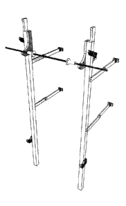
Referring now to FIG. 3, a perspective view of the invention is shown. This is
a three-
quarter top down view to show the relationship of all parts and their relative
location on the first
embodiment.
Docket No. SNJ-101 Page 15
CA 3045654 2019-06-10
Referring now to FIG. 4, a side view and a perspective view of the first
embodiment is
shown with the scissor arms 10 folded for easy storage closer to the object to
which they are
mounted. The mounting object is typically a wall, but can also be any large
sturdy structure, such
as a tree or deck. In this view, cotter pins 20 have been removed from the
scissor arms 10, which
are folded in towards each other to move the ladder closer towards a wall.
An electromagnet 6 is used to hold each spring-loaded arm 2 in place as the
athlete hops
the bar 14 onto the spring-loaded arm 2. When the athlete is on the spring-
loaded arm 2, a sensor
12 is tripped, the power is turned off, the spring-loaded arm 2 pivots on the
axle 3, and drops the
athlete back onto the adjustable fixed arm 4. Each electromagnet 6 is rated to
hold in excess of
150 lbs, giving it a combined rating of more than 300 lbs. The electromagnet 6
makes contact
with the spring-loaded arm 2 with a square piece of metal that extends 90
degrees from the back
thereof. The electromagnet 6 aides in manufacturing because it is an
inexpensive, off the shelf
product that works 100% of the time with no moving parts.
An adjustable spring 7 attaches to the frame 1 and the spring-loaded arm 2.
After the
spring-loaded arm 2 pivots and drops the athlete back to his starting
position, the adjustable
spring 7 returns the spring-loaded arm 2 to its start position. Each spring 7
has a rating of 20 lbs
and, in this embodiment, is attached to the frame 1 with an adjustable
connector to raise or lower
the tension. The tension can be adjusted for a lighter or heavier athlete or
for personal preference.
Docket No. SNJ-101 Page 16
CA 3045654 2019-06-10
A locking lever 8 rotates on the adjustable fixed frame 4 and locks the pull-
up bar 14 in
place for standard pull-up exercises. The locking lever 8 also locks in
accessory specialty bars
for the ladder.
As mentioned hereinabove, supporting the frame 1 to a wall are four scissor
arms 10. The
ladder can also be mounted to wall studs, the side of a house, the side of a
deck, or any rigid
structure. The scissor arms 10 serve two purposes. The primary purpose is to
act as a bracket to
hold the frame 1 upright on the floor. The second purpose is to fold the
entire unit to the wall,
and then into position to use for the exercise.
The scissor arms 10 are hinged and collapse with the help of hinged, wall
mounting
brackets 11. Wall mounting brackets 11 are bolted directly into the wall stud
or a 2x4 cross
member using heavy duty lag bolts, not shown. With the scissor arms 10 folded,
the ladder folds
within a foot of a proximate wall to take up less space. The scissor arms 10
mount to the frame 1
on one side and the wall bracket 11 on the other. The scissor arms 10 pivot on
the frame 1, pivot
together in the center of the arm, and pivot again at the wall bracket 11,
locking in the open
position using the removable, locking cotter pins 20.
A reed field sensor 12 is a standard field sensor that is mounted where the
frame 1 and
spring-loaded arm 2 meet. The reed field sensor 12 senses the proximity of the
pull-up bar 14
after the athlete has completed the hop to the spring-loaded arm 2. The pull-
up bar 14 trips the
reed field sensor 12, which sends an electrical signal to a timer 15, which is
an electronic circuit
Docket No. SNJ-101 Page 17
CA 3045654 2019-06-10
inside a circuit box on or inside the frame 1. The timer 15 waits one second,
then cuts power to
the electromagnet 6, then counts back to one second and restores power to the
electromagnet 6,
finishing the cycle.
Referring now to FIG. 5, a perspective view of the invention is shown. Using
the
freestanding brackets 22, the ladder can be quickly assembled in a
freestanding position without
a wall or sturdy structure. The freestanding brackets 22 use a locking hinge
18 so the
freestanding brackets 22 can fold and unfold easily for transport and
assembly. The locking hinge
18 employs a metal tab to prevent the freestanding brackets 22 from
inadvertently folding while
the athlete is using the ladder, thereby increasing safety.
Referring now to FIG. 6, an exploded perspective view of the invention is
shown. This
three-quarter top down exploded view shows the assembly of the first
embodiment and how it is
assembled onto the frame 1.
Referring now to FIG. 7, a front view of the 12-foot embodiment is shown. In
this
embodiment, the removable pegs 16 can be used instead of the spring-loaded arm
2 to allow the
athlete to move the pull-up bar 14 up the removable pegs 16, thereby
increasing the challenge to
the athlete. In this embodiment, the removable pegs 16 can be configured in
different intervals to
give the athlete the desired challenge.
Docket No. SNJ-101 Page 18
CA 3045654 2019-06-10
Referring now to FIG. 8, a side view of the 12-foot embodiment is shown. This
view
shows the location of a tie bar 21. This view shows the relationship of the
fixed brackets 17,
locking hinge 18, removable pegs 16, and foot pegs 5. Removable pegs 16 are at
placed at a six-
inch distance from one another. They can be removed and re-configured to a 12-
inch or 18-inch
distance. The tie bar 21 is attached to the top of the frame 1 to connect the
two pieces of the
frame 1 and make the apparatus sturdier. The tie bar 21 is made from a sturdy,
structural steel
tubing, hollow to allow the wiring to pass between the two frames 1.
Referring now to FIG. 9, a close-up side view of the 12-foot embodiment is
shown. This
view shows the relationship of the removable pegs 16 to one another and how
the pull-up bar 14
makes contact with the frame 1 and removable pegs 16. The dotted lines show
how the pegs 16
can be removed for different distance configurations. A locking hinge 18 is
also shown in
position.
The removable pegs 16 in this embodiment are three-quarter diameter, mild
steel pegs
that are rated to hold up to 300 lbs. The removable pegs 16 hold the pull-up
bar 14 and, by
default, the athlete. A stop pin 19 prevents each peg 16 from falling out. The
removable cotter
pin 20 locks it in from the back so it cannot fall out the front. The cotter
pin 20 is easily installed
or removed by hand.
Referring now to FIG. 10, a perspective view of the 12-foot embodiment of the
ladder is
shown with fixed mounting brackets 17. This three-quarter top down view shows
the relationship
Docket No. SNJ-101 Page 19
CA 3045654 2019-06-10
between the frame 1, fixed brackets 17, tie bar 21, removable pegs 16, pull-up
bar 14, and
locking hinges 18, which are heavy duty hinges that allow the upper and lower
halves of the
frame to be folded for shipping, setup and storage of the ladder.
Referring now to FIG. 11, the lower frame 23 and frame 1 are shown folded for
shipping,
easy setup, and storage. Lower frame 23 comprises a rigid material with a
substantially square
steel frame. In this first embodiment, the lower frame 23 is made of square
structural steel. The
lower frame 23 is the bottom half of the 12-foot embodiment. The lower frame
23 uses the
locking hinge 18 to fold adjacent to the frame 1 for easy shipping and
assembly, due to the
locking hinge 18.
Referring now to FIG. 12, side and front views of the removable pegs 16 are
shown. The
stop pin 19 keeps each peg 16 from falling out of the back of the frame 1, and
the cotter pin 20
locks the pin in from the back. The stop pin 19 is a one-eighth inch diameter,
hardened dowel pin
pressed in the removable peg 16. The cotter pin 20 can be taken out easily by
hand to reconfigure
the removable pegs 16.
Referring now to FIG. 13, a perspective, three-quarter top down view of the 12-
foot
embodiment of the ladder is shown with scissor arms 10 and wall mounting
brackets 11. This
view shows how the cotter pin 20 fits into each scissor arm 10. The removable
cotter pin 20
easily slides into removable peg 16 and locks it into place so the removable
peg 16 cannot be
removed from the front of the frame 1. The cotter pin 20 is meant to be easily
installed and
Docket No. SNJ-101 Page 20
CA 3045654 2019-06-10
removed by hand so that the pegs 16 can quickly and easily be configured for
the athlete. The
cotter pin 20 is also used in the scissor arms 10 to lock them in position.
Referring now to FIG. 14, a perspective view of the 12-foot embodiment of the
ladder is
shown, depicting the relationship of the frame 1 with freestanding brackets 22
and locking
hinges 18. The freestanding bracket 22 is composed primarily of a rigid
material. In this first
embodiment, it is made out of structural tube steel. The freestanding bracket
22 attaches to the
frame 1 so the ladder can stand freely without being bolted to a wall or other
sturdy structure.
The locking hinge 18 is used to fold the legs of the freestanding bracket 22
in half for easy set up
and shipping.
Referring now to FIG. 15, there is shown a perspective view of another
embodiment of
the plyometric ladder in accordance with the present invention. In this
embodiment, only a
skeletal frame is present. It is therefore known as a frameless ladder. Wall
brackets are not
needed, nor are electromagnets, which are replaced with a 12-volt DC motor 10'
and a lever stop
11', supported by a lever bracket 13' (FIG. 16). An existing, commercial squat
rack l' supports a
1 1/2 inch diameter pull-up bar 2'.
Referring now also to FIG. 16, a side view of the frameless plyometric ladder
is shown.
The motor 10', supported by a motor bracket 12', retracts the lever stop 11'
to release the athlete,
then replaces the lever stop 11' after a return spring 18' returns a spring
lever mounted on axle
15' to its original position. A skeletal aluminum frame 3' of the ladder fits
on an existing
Docket No. SNJ-101 Page 21
CA 3045654 2019-06-10
commercial squat rack 1'. A fixed arm 4' is attached to the skeletal frame 3',
as is a lever arm 5'.
A shock absorber spring 8' is operationally connected to and supported by a
shock absorber base
9'.
An athlete uses the frameless exercise ladder in the same way as described
hereinabove
with respect to the first embodiment of the present invention. That is, the
athlete performs a pull-
up on pull-up bar 2' and then hops the bar up while hanging therefrom an
adjustable distance,
hangs for an adjustable time, then the spring-loaded arm pivots and releases
the athlete to ride
down the fixed arm 4' to the starting point to begin the cycle again.
Referring now also to FIG. 17, which is a front view of the frameless
plyometric ladder,
and to FIG. 18, which is a top view of the ladder, bracket clamps 6' are
positioned at the top and
bottom of skeletal aluminum frame 3' with bracket locking levers 7' attached
thereto. At the
extremity of the bracket clamps 6' and bracket locking levers 7' are spring-
loaded locking pins
14'. A momentary switch 16', electrically connected to an electronic box 17',
activates and
deactivates the motor 10'.
Since other modifications and changes varied to fit particular operating
requirements and
environments will be apparent to those skilled in the art, the invention is
not considered limited
to the example chosen for purposes of disclosure and covers all changes and
modifications which
do not constitute departures from the true spirit and scope of this invention.
Docket No. SNJ-101 Page 22
CA 3045654 2019-06-10
Having thus described the invention, what is desired to be protected by
Letters Patent is
presented in the subsequently appended claims.
Docket No. SNJ-101 Page 23
CA 3045654 2019-06-10
Docket No. SNJ- 101 Page 24
CA 3045654 2019-06-10