Note: Descriptions are shown in the official language in which they were submitted.
CA 03045717 2019-05-30
WO 2018/166963 PCT/EP2018/056059
1
An implant needle
The present disclosure relates to an implant needle for introducing an implant
into a body of
a patient.
Background
For inserting implants, e.g. sensors, into the skin up to an insertion depth
of approximately 10
mm different types of implant cannula or needles are known, e.g. closed
cannulas with a V-
bevel, oval-shaped slotted cannulas with a V-bevel, and peel catheters, i.e. a
cannula tube
divided into two with a V-bevel which is then opened in the skin and removed
in separate
parts.
A flat sensor cannot be inserted into the skin with closed implant needles
with a V-bevel,
tubular. Oval-shaped slotted implant cannulas or needles are more expensive to
manufac-
ture than tubular slotted cannulas. They are predominantly used for 90
insertion angles.
Peel catheters are also more expensive to manufacture and usually are only
allowed to be
inserted and removed by a doctor or nurse.
Document WO 2015 / 128263 Al discloses an implant needle for introducing an
implant into
a body of a patient is provided. The implant needle comprises a receiving
portion configured
to receive an implant and provided in a hollow needle main body, and a taper-
shaped tip
portion formed by cutting a tip portion of the hollow needle main body. The
implant needle
may also be referred to an implant cannula. The taper-shaped tip portion
comprises a first
slant surface provided contiguous to an outer peripheral surface of the hollow
needle main
body. The first slant surface is formed at a pre-determined angle with respect
to an axis of
the needle main body. The first slant surface may also be referred to as
primary or base cut.
The taper-shaped tip portion further comprises a pair of second slant surfaces
contiguous to
the first slant surface and symmetric with respect to an edge point and the
axis of the hollow
needle main body. The pair of second slant surfaces is formed at a larger
angle with respect
to the axis of the needle main body than the predetermined angle with respect
to the axis of
the needle main body. The pair of second slant surfaces may also be referred
to as facet cut.
An outer edge of the pair of second slant surfaces is provided as a cutting
edge contiguous
to the edge point. The inner and outer edges of the first slant surface are
provided as non-
cutting edges.
CA 03045717 2019-05-30
WO 2018/166963 PCT/EP2018/056059
2
Document DE 10 2011 112 021 Al discloses a needle or cannula prided with a
tapered tip
portion. Also, Document DE 102 24 101 Al refers to cannula prided with a
tapered tip por-
tion. There are a first slant surface provided contiguous to an outer
peripheral surface of the
hollow needle main body and a pair of second slant surfaces contiguous to the
first slant sur-
face and symmetric with respect to an edge point and the axis of the hollow
needle main
body.
Document WO 99 / 53991 Al refers to an implant retention trocar which includes
a cannula
for puncturing the skin of an animal and an obturator for delivering the
implant beneath the
skin of the animal. The implant retention trocar has a cannula distal tip
design which causes
a minimum of trauma and tearing of tissue during implant insertion. A spring
element re-
ceived within the cannula prevents an implant which is to be inserted into an
animal from
falling out of the cannula during the implant insertion process. The spring
element includes a
longitudinal leg which is folded with a zig-zag shaped bend. When the spring
element is in-
serted into the cannula the zig-zag shaped bend of the shaped bend of the
longitudinal leg
retains the implant within the cannula.
Document US 2010 / 324579 discloses an instrument with a covered bore for
subcutaneous
implantation. An incising body defines a non-circular coaxial bore and
includes a sharpened
cutting edge that extends from a bottom distal end beyond the opening of the
coaxial bore
and an attachment point at a top distal end. A plunger is non-fixedly
contained within the co-
axial bore and slides longitudinally therein. A cover is pivotally attached at
the attachment
point and extends down to the bottom distal end and, when closed, the cover
encloses the
opening proximal to the cutting edge.
Document US 3,064,651 relates to a hypodermic needle comprising an axial bore
and being
beveled at its outer end to provide a tissue penetrating tip and an obliquely
disposed bore
orifice extending rearwardly from said tip.
Document US 3,448,740 refers to a non-coring hypodermic needle, comprising a
heel portion
and a tip portion terminating in a piercing point characterized in that at
least one side wall
portion is spirally curved from the piercing point to the heel portion and the
heel portion is
rotatably displaced approximately within the range of 260 to 280 and
preferably about 270
from the piercing point in the same direction as the direction of spiral of
said side wall portion.
CA 03045717 2019-05-30
WO 2018/166963 PCT/EP2018/056059
3
Document WO 2005 / 044116 discloses a cutting device for a blunt needle or
transcutaneous
sensor for insertion through the derma of a patent, said blunt needle or
transcutaneous sen-
sor having a circumference at the distal end, said cutting device comprising a
base part and
a cutting member for making an incision in the derma, said base part having a
track adapted
for slideable engagement with the needle or transcutaneous sensor, wherein the
cutting
member has a cutting width, W, being less than half the length of the
circumference of the
blunt needle or transcutaneous sensor,
Document US 4.490,139 refers to a subcutaneous implant needle formed as a
hollow tube
having its forward end cut on a plane at an acute angle to the central axis of
the tube to form
an elliptical opening, and an elliptical outer edge having a sharp forward
portion. The forward
extremity of the needle is dressed to form cutting edges intersecting at an
obtuse angle and
forming a central point. The dressed edges have a width preferably less than
two-thirds the
diameter of the tube, and the adjoining side portions of the elliptical outer
edge are rendered
non-sharp and dulled, as by abrasion such as sandblasting or tumbling in
abrasive media.
The needle is dimpled at two locations closely adjacent the rear of the
opening.
Document EP 1 491 225 Al discloses an injection needle comprising a needle tip
provided
by forming at least two or more ground surfaces after a first ground surface
is formed at the
tip of a needle tube, characterized in that the needle tip is not present on a
central plane,
where a plane vertically crossing the first ground surface and including the
center axis of the
needle tube is the central plane, whereby the injection needle can reduce
boring pain provid-
ed to a patient when the needle is pierced into a skin.
Document DE 42 35 483 Al refers to a hollow cannula for injection or liquid
withdrawal that
has circular shaft cross-section and an inclined ellipsoidal piercing face
with two side cutting
edges which meet at the cannula tip. The cannula is asymmetrical in the region
of the cutting
edges. The cutting edges may have unequal lengths and/or form unequal angles
with the
cannula axis.
Document US 2005 / 251190 Al relates to a tissue penetrating instrument of the
type used in
the medical field and which may or may not be embodied in the form of an
obturator associ-
ated with a trocar assembly, wherein the instrument includes an elongated
shaft having a
penetrating tip mounted on one end thereof. The penetrating tip includes a
base secured to
the one end of the shaft, and a distal extremity spaced longitudinally outward
from the base
CA 03045717 2019-05-30
WO 2018/166963 PCT/EP2018/056059
4
and formed into an apex which may be defined by a point or other configuration
specifically
structured to facilitate penetration or puncturing of bodily tissue. The apex
may be substan-
tially aligned with a linear extension of the central longitudinal axis of the
shaft or alternative-
ly, may be spaced laterally outward or off-set from the central longitudinal
axis of the shaft.
The penetrating tip further includes an exterior surface extending
continuously between the
apex and the base and configured to facilitate puncturing of the tissue and an
enlargement of
an access opening formed in the tissue, in a manner which facilitates
separation of the tissue
and minimizes cutting, severing or otherwise damaging the contiguous bodily
tissue sur-
rounding the access opening.
Summary
It is an object to provide an improved implant needle for introducing an
implant, for example
a sensor device such as an analyte sensor, preferably an electrochemical
sensor such as a
glucose sensor, into a body of a patient. The implant needle shall allow for
non-destructive
implantation of the implant.
The implant needle may be configured for implanting an implant transcutaneous
where a part
of the implant is placed under the skin and another part of the implant is
above the skin. In an
alternative, the implant needle may be configured for a full implantation
where the entire im-
plant is placed under the skin. Further, the implant needle shall support
conservative implan-
tation into the patient's body.
According to the present disclosure, an implant needle for introducing an
implant into a body
of a patient according to claim 1 is provided. Alternative embodiments are
disclosed in the
dependent claims.
According to an aspect, an implant needle for introducing an implant into a
body of a patient
is provided. The implant needle comprises a receiving portion configured to
receive an im-
plant and provided in a hollow needle main body, and a taper-shaped tip
portion. The taper-
shaped tip portion is further comprising: a first slant surface contiguous to
a first outer pe-
ripheral surface of the hollow needle main body, wherein the first slant
surface is provided as
a first non-cutting edge; a second slant surface contiguous to a second outer
peripheral sur-
face of the hollow needle main body, wherein the second slant surface is
provided as a sec-
ond non-cutting edge; and a pair of sharpened surfaces symmetric with respect
to an edge
CA 03045717 2019-05-30
WO 2018/166963 PCT/EP2018/056059
point and an longitudinal axis of the needle main body, wherein the sharpened
surfaces are
both provided with a cutting edge. The first slant surface comprises a first
flank, and the sec-
ond slant surface comprises a second flank. The first flank is provided at a
first distance from
the edge point, and the second flank is provided at a second distance from the
edge point
5 which is different from the first distance.
A hollow needle main body of an implant needle in the sense of the application
is a hollow
body that is provided with an opening extending in a longitudinal direction of
the implant nee-
dle in a side of the hollow needle main body. Thus, the hollow needle main
body may also be
referred to as an open hollow needle main body. In other words, the hollow
needle main
body is not a cannula provided with a closed tube shape.
The opening in the side of the hollow needle main body may extend along the
entire length of
the hollow needle main body. Alternatively, the opening in the side of the
hollow needle main
body may only extend along part of the length of the hollow needle main body.
In case the
opening extends only along part of the length of the hollow needle main body,
the opening
extends to a distal end of the hollow needle main body, providing an opening
towards the
taper-shaped tip portion.
The opening in the side of the hollow needle main body may be formed symmetric
with re-
spect to the longitudinal axis of the needle main body. The opening in the
side of the hollow
needle main body may be provided as a slot opening. Thereby, a slotted hollow
needle main
body may be provided.
The opening in the side of the hollow needle main body may enable a contacting
end of an
implant to be placed in a position outside the receiving portion of the hollow
needle main
body.
The opening in the side of the hollow needle main body may enable retracting
the implant
needle from the body of the patient when the implant has been inserted without
changing the
position of the implant.
Inner edges formed in the range of the opening in the side of the hollow
needle main body
may be provided as non-cutting edges.
CA 03045717 2019-05-30
WO 2018/166963 PCT/EP2018/056059
6
The tapered tip portion, for example, may be formed by cutting a tip portion
of the hollow
needle main body.
The sharpened surfaces both may be provided as a non-slanted surface in a flat
tip portion
contiguous to the edge point. The flat tip portion may be symmetric to the
longitudinal axis of
the needle main body.
At least one of the first and second flanks may be contiguous to one of the
sharpened sur-
faces.
At least one of the first and second flanks may be contiguous to the cutting
edge provided to
the one of the sharpened surfaces.
At least another one of the first and second flanks may be contiguous to a non-
sharpened
surface which in turn is contiguous to the sharpened surface having the
cutting edge. The
non-sharpened surfaces are free of any cutting edge, thereby, being provided
with non-
cutting edges. The non-sharpened surface may be provided in the flat tip
portion.
For at least one of the first and second flanks, the first and second outer
peripheral surface
may be bent outwardly.
For at least one of the sharpened surfaces the cutting edge may be provided on
an outer
edge. An inner edge may be provided with a non-cutting edge. In an alternative
embodiment,
the inner edge may be provided with a cutting edge, while the outer edge is
provided with a
non-cutting edge. In still a further alternative embodiment, both the outer
edge and the inner
edge of the sharpened surfaces may be provided with a cutting edge.
The first and second flank both may be provided as a punch-bent component.
At least one of the first and second flanks may be provided adjacent to a flat
portion distal to
the edge point.
The flat portion may be contiguous to the flat tip portion.
CA 03045717 2019-05-30
WO 2018/166963
PCT/EP2018/056059
7
The receiving portion may comprise a recess extending through the needle main
body. The
recess may be formed symmetric with respect to the longitudinal axis of the
needle main
body.
The hollow needle main body may be provided with one of a round cross-section
and an oval
cross-section.
The tapered tip portion may be provided with a flat portion.
In the sense of the application, a cutting edge will cut the skin while a non-
cutting edge will
not usually cut the skin. For example, a cutting edge may be obtained by
thinning of material
towards the edge.
Non-cutting edges, for example, can be produced by grinding or laser cutting
or water cut-
ting. Non-cutting edges may be produced by rounding edges after cutting the
material.
One or more of the non-cutting edges may be provided as rounded edges.
Finishing through
blasting with materials or polishing may be used for rounding the edge.
Blasting can be car-
ried out with, for example, glass spheres, corundum, and sand. A well-known
method is pal-
ishing, for example electropolishing in fluid.
In the process of production, rounding may be provided by grinding and/or
electropolishing.
In addition or as an alternative, abrasive material blasting may be used.
Alternatively, the
non-cutting edges may be produced by applying abrasive material blasting only.
The hollow needle body may be provided with a U- or V-shaped cross section in
the receiv-
ing portion. With respect to the taper-shaped tip portion, a bevel may be
provided. The open-
ing in the side of the hollow needle main body may be contiguous to the bevel
provided with
respect to the taper-shaped tip portion.
In the following it is described how the implant needle can be manufactured.
The method
may comprise a) punching a flat metal strip or sheet so as to give rise to a
flat sheet of a de-
sired shape suitable for later bending the sheet so as to give rise to the
shape of the cannula
or implant needle. In a second step b) the sheet may then be subjected to
embossing of the
"dull" non-cutting edges in the portion of the sheet. Then, in a step c) the
cannula may be
CA 03045717 2019-05-30
WO 2018/166963 PCT/EP2018/056059
8
bent and the tip of the cannula may be embossed and punched out so as to give
rise to the
cannula of the invention. As an alternative, etching methods can be used to
create a sharp
tip of the cannula.
.. The method for manufacturing the implant needle may comprise producing at
least the first
and second flanks by at least one of a punch-bent process or an etching
process combined
with a bent process. The punch-bent process combining punching and bending the
material
used for manufacturing the implant needle are combined for producing at least
one of the
flanks. Such punch-bent process may be used for manufacturing the hollow
needle main
body as well.
The method may comprise: Providing a hollow needle main body having a lumen
surrounded
by a peripheral wall and a receiving portion configured to receive an implant
and provided in
the hollow needle main body. The taper-shaped tip portion is produced with a
first slant sur-
face contiguous to a first outer peripheral surface of the hollow needle main
body, wherein
the first slant surface is provided as a first non-cutting edge; a second
slant surface contigu-
ous to a second outer peripheral surface of the hollow needle main body,
wherein the second
slant surface is provided as a second non-cutting edge; and a pair of
sharpened surfaces
symmetric with respect to an edge point and an longitudinal axis of the needle
main body,
wherein the sharpened surfaces both are provided with a cutting edge. The
first slant surface
comprises a first flank and the second slant surface comprises a second flank.
The first flank
is provided at a first distance from the edge point and the second flank is
provided at a sec-
ond distance from the edge point which is different from the first distance.
Description of further embodiments
In the following, further embodiments will be described by way of example. In
the figures
show:
Fig. 1 a top view of a tip section of an implant needle having a hollow
needle or cannula
main body provided with a taper-shaped tip portion;
Fig. 2 a side view of the tip section in Fig. 1;
Fig. 3 an implant needle with symmetrical flank known in the art;
Fig. 4 a implant needle, wherein a first flank is provided at a first
distance from an edge
point, and a second flank is provided at a second distance from the edge point
which is different from the first distance:
CA 03045717 2019-05-30
WO 2018/166963 PCT/EP2018/056059
9
Fig. 5 a graphical representation of the penetration force the implant needle
shown in
Fig. 3;
Fig. 6 a graphical representation of the penetration forces of the implant
needle shown in
Fig. 4; and
Fig. 7 experimental results for the implant needle in Fig. 4.
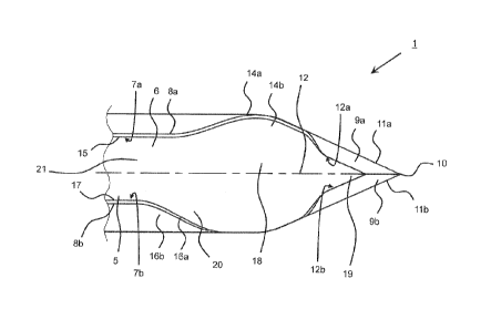
Referring to Fig. 1 and 2, an implant needle 1 having a hollow needle or
cannula main body 2
is provided. The hollow needle main body 2 is provided with a taper-shaped tip
portion 3 at
an end 4.
The hollow needle main body 2 comprises a receiving section 5 provided with an
opening
extending in a longitudinal direction of the implant needle which, in the
embodiment shown,
is in the form of a slot opening 6. The slot opening 6 may extend along the
entire length of
the hollow needle main body 2 (not shown in its entire length in Fig. 1 and 2)
or along a sec-
tion of the hollow needle main body 2.
The receiving section 5 is configured to receive an implant element (not
shown), e.g. a sen-
sor, to be introduced into the body of a human being or an animal through the
skin by the
implant needle 1. For implantation the implant is located in the receiving
section 5. After
puncturing through the skin into the body, the implant needle 1 is retracted
leaving the im-
plant in the body. The implant element slides out of the receiving section 5
when the implant
needle 1 is retracted.
Inner edges 7a, 7b formed in the range of the slot opening 6 or the receiving
section 5 are
provided as non-cutting edges. This will also support preventing the implant
element from
damage when the implant element is leaving the receiving section 5 during
implantation. Al-
so, outer edges 8a, 8b are provided as non-cutting edges.
In the taper-shaped tip portion 3, a pair of sharpened surfaces 9a, 9b is
provided. The pair of
sharpened surfaces 9a, 9b is formed contiguous to an edge point 10. Outer
edges 11a, 11 b
of the sharpened surfaces 9a, 9b are provided as cutting edges. Inner edges
12a, 12b of the
sharpened surfaces 9a, 9b, according to the embodiment shown, are provided as
non-cutting
edges.
CA 03045717 2019-05-30
WO 2018/166963
PCT/EP2018/056059
The sharpened surfaces 9a, 9b are symmetric to the edge point 10 and a
longitudinal axis 12
of the needle main body 2.
A first slant surface 14a is provided on a first flank 14b contiguous to a
first outer peripheral
5 surface 15 of the hollow needle main body 2. A second slant surface 16a
is provided on a
second flank 16b contiguous to a second outer peripheral surface 17 of the
hollow needle
main body 2. The first flank 14b is provided at a first distance from the edge
point 10. The
second flank 15b is provided at a second distance from the edge point 10,
wherein the first
distance is different from the second distance, thereby, providing an
asymmetric design of
10 location for the first and second flank 14b, 16b with regard to the edge
point 10.
The first flank 14b is provided adjacent to a flat portion 18 which in turn is
contiguous to a flat
tip portion 19. In the embodiment shown, the first flank 13b is provided in a
center portion of
the flat portion 18, while the second flank 16b also located adjacent to the
flat portion 18 is
provided in a distal end portion 20 of the flat portion 18, the distal end
portion 18 being more
distant to the edge point 10. The second flank 16b may be located in a
transition portion in
which a non-flat portion 21 of the hollow needle main body 2 is contiguous to
the flat portion
18.
With regard to the first and the second flanks 14b, 16b, the first and second
outer peripheral
surfaces 15, 17 is bent outwardly. The extent to which the first and second
outer peripheral
surfaces 15, 17 are bent outwardly may be the same. In an alternative, the
first and second
outer peripheral surfaces 15, 17 may be bent outwardly to different extent,
If the implant needle 1 is used for cutting a skin the skin is cut by the
sharpened surfaces 9a,
9b. Following, because of the non-cutting edges the skin is lifted by the
first and the second
flank 14b, 16b. Firstly, the skin is lifted by the first flank 14b on the one
side of the implant
needle 1. Later when the taper-shaped tip portion 3 is further introduced into
the skin, the
skin is lifted by the second flank 16b. Therefore, the lifting of the skin is
done step by step
which supports an un-destructive implantation of the implant to be introduced
in the patient's
body by the implant needle 1.
In the process of manufacturing the implant needle 1 at least the first and
second flanks 14b,
16b may be produced by at least one of a punch-bent process and an etching
process corn-
bined with a bent process. The punch-bent process combining punching and
bending the
CA 03045717 2019-05-30
WO 2018/166963 PCT/EP2018/056059
11
material used for manufacturing the implant needle 1 are combined for
producing at least
one of the first and second flanks 14b, 16b. Such punch-bent process may be
used for man-
ufacturing the hollow needle main body 2 as well.
The method for production may comprise punching a flat metal strip or sheet so
as to give
rise to a flat sheet of a desired shape suitable for later bending the sheet
so as to give rise to
the shape of the cannula. In a further step, the sheet may then be subjected
to embossing of
the "dull" non-cutting edges in the portion of the sheet. Then, in another
step, the cannula
may be bent, and the tip portion of the cannula may be embossed and punched
out so as to
give rise to the cannula. As an alternative etching methods can be used to
create a sharp tip
of cannula.
The implant needle according to the alternative embodiments provides for the
surprising ad-
vantage that the manufacturing of the implant needle which starts with a flat
metal sheet al-
lows for cheaper and faster production of the needle than the expensive
manufacturing pro-
cesses used to generate state of the art needles made by cutting and
sharpening of cylindri-
cal closed metal cylinders.
Different cannula or implant needle types were tested. Fig. 3 shows an implant
needle having
symmetrical flank and a cross section essentially round as known in the art.
Fig. 4 shows an
implant needle 1 as depicted in Fig. 1 and 2.
Fig. 5 and 6 each how a graphical representation of the penetration force
measured for the
implant needle shown in Fig. 3 and the implant needle shown in Fig. 4,
respectively.
The implant needle from Fig. 1, 2, and 4 are configured to support reduced
penetration forc-
es during insertion into skin when compared to the implantation needle with
symmetrical
edges such as the one depicted in Fig. 3. This surprising result in turn
reduces the pain for
the patient using such needles.
The implant needles from Fig. 3 and 4 were tested by simulating insertion into
human skin by
a procedure according to German standard DIN 13097-4 as follows: A (PUR) film
according
DIN 13097-4 (polyurethane testing foil strips by melab Medizintechnik und
Labor GmbH,
Leonberg, Germany) was fixed in a test stand and used in place as a model
system of skin.
CA 03045717 2019-05-30
WO 2018/166963 PCT/EP2018/056059
12
In each test, an individual piece of the FUR film was penetrated by the
implant needle under
investigation.
For each of the two implant needles, the following parameters as well as their
respective
mean values and standard deviations were determined: FO - Force [N] exerted by
the needle
tip penetrating the FUR film; Fmax - Maximal force [N] exerted by entry of the
broadest part
of the needle tip (represented by the respective tips flank or flanks) into
the FUR film; and
Fmin - Minimum force [N] exerted when the needle is retracted from the PUR
film.
The experiment was performed according to standard DIN 13097-4 for penetration
testing.
The test procedure comprises the consecutive steps of clamping of the implant
needle, start-
ing the software routine, moving of the FUR film and unclamping of the implant
needle.
Fig. 7 depicts experimental results for the implant needle in Fig. 4 referred
to "C2.1-x" with
x = 1... 20. The average value of maximal penetration forces Fmax detected for
the tested
implant needles is 2,63N.
The implant needle from Fig. 4 shows a lower maximal penetration force Fmax,
and also the
lowest standard deviation. The implant needle from Fig. 4 is associated with a
superior per-
formance under the conditions of the model skin which supports the view that
comparable
performance can be demonstrated under the "physiological" circumstances of an
insertion
into the skin of a user.
It is noteworthy that the implant needle from Fig. 3 having symmetrical flanks
showed a low
performance (see below). The needle cross section in the area of the tip led
to an increased
penetration force which should be associated with an increased pain for the
patient when
compared to the implant needle in Fig. 4.
Referring to Fig. 5, when penetrating the model skin with the implant needle
from Fig. 3 both
symmetrical flanks penetrated the film simultaneously and the widening of the
skin model
took place in one step. The maximum force was exerted when both flanks entered
the skin
model. In Fig. 5 there are two local maxima: 50 - entry of the needle tip into
the skin, and 51 -
entry of the needle flanks.
CA 03045717 2019-05-30
WO 2018/166963
PCT/EP2018/056059
13
Table 1 shows experimental results for the implant needle in Fig. 3.
Table 1
Series n=50 Fmax [N]
Minimum force 2,77
Maximum force 3,31
Mean value 3,1
Standard deviation 0,11
Range 0,81
Referring to Fig. 6, when penetrating the model skin with the implant needle
from Fig. 4 the
flanks penetrated the film at different times, i.e. the flank provided as a
shorter distance from
the edge point penetrated the film before the flank provided as a larger
distance from the
edge point 10. The maximum force was exerted when both flanks entered the skin
model. In
Fig. 6 there are three local maxima: 60 - entry of the needle tip into the
skin, 61 - entry of the
.. first needle flanks, and 62 - entry of the second needle flank. While the
entry of the needle tip
60 is a rather small local maximum, the other maxima are well established on
the plot shown
in Fig. 6.
Table 2 shows experimental results for the implant needle in Fig. 4.
Table 2
Series n=20 Fmax [N] dL (Fmax) Fmin [NI] dL (Fmin)
[mm] [mm]
Minimum force 2,47 2,5 -2,2 4,5
Maximum force 2,78 0,7 0,0507 0,2
Mean value 2,63 4,2 -2,12 5,2
Standard deviation 0,0797 5,6 -2,03 5,4
The second maximum 61 in the plot "deformation path versus penetration force"
in Fig. 6 was
due to the fact that the first flank raised the PUR film and widened the
puncture site further
without cutting. Then the force dropped slightly, since only the sliding
friction prevailed. The
third maximum 62 was due to the fact that the second flank raised the PUR film
and finally
expanded the puncture site to the implant needle cross-section. After that
there was only
sliding friction.
CA 03045717 2019-05-30
WO 2018/166963
PCT/EP2018/056059
14
The asymmetry of the cannula flanks along the longitudinal axis resulted in a
reduction of the
incision force of about 3N to about 2.6N compared to the prior art needle,
which was due to
the fact that the expansion of the PUR film at the puncture site took place
gently and step by
step by one flank after the other and on a longer puncture path.
The sliding friction of the implant needle from Fig. 4 was still unchanged at
the same level
between 2N and 2.1N.
Based on the above results, implant needle from Fig. 4 provides for
significantly reducing
maximum penetration forces of the PUR film compared to the known implant
needle.