Note: Descriptions are shown in the official language in which they were submitted.
CA 03045878 2019-05-28
DESCRIPTION
VIBRATING SIEVE MACHINE
TECHNICAL FIELD
[0001]
The present invention relates to vibrating sieve machines for classifying. by
vibrations, powders of various materials, such as medicines, foods, mineral
products, metals.
and resin raw materials. More particularly, the present invention relates to a
vertical
vibrating sieve machine capable of having a smaller body height.
BACKGROUND ART
[0002]
A conventional vertical vibrating sieve machine is provided with a vibrating
plate
that is supported by a plurality of compression coil springs on a supporting
table in a manner
that allows the vibrating plate to vibrate. A sieve frame that holds a mesh
member is fixed to
the vibrating plateõ A vibrating motor is provided on each of opposite sides
in the horizontal
direction of the sieve frame. When the opposite vibrating motors are operated,
vibrations are
applied through the sieve frame to powder to be classified that is placed on
the mesh member
for sieving and classification (see Patent Document ).
CITATION LIST
PATENT LITERATURE
[0003]
Patent Document I Japanese Registered !Ally Model No, 3188460
CA 03045878 2019-05-28
[0004]
As shown in FIG. 11. in a vibrating sieve machine 100 described in Patent
Document I. a sieve frame 101 includes an upper separable sieve frame 101a and
a lower
separable sieve frame 101b, which can be vertically separated from each other.
A mesh
member 102 is disposed inside the sieve frame 101 at or near a boundary
between the upper
separable sieve frame 101a and the lower separable sieve frame 101h.
[0005]
The mesh member 102 includes: a mesh member body 103 having a circular
annular mesh member frame 104 and a reinforcement mesh 105 stretching across
the mesh
member frame 104; a sieve mesh 106 that is put on top of the mesh member body
103,
covering the reintOrcement mesh 105 and hanging down over an outer peripheral
surface of
the mesh member frame 104; and a fastening band 107 that is attached to the
outer peripheral
surface of the mesh member frame 104 so that the sieve mesh 106 is sandwiched
between the
outer peripheral surface of the mesh member frame 104 and the fastening band
107, whereby
the sieve mesh 106 is tied and fixed to the mesh member body 103.
SUMMARY OF INVENTION
TECHNICAL PROBLEM
[0006]
However, in the conventional vibrating sieve machine 100, the mesh member
frame
104, which does not substantially contribute to sieving and classification of
powder to be
classified, is entirely housed inside the sieve frame 101 (the upper separable
sieve frame
101a). Therefore. the effective areas of the reinforcement mesh 105 and the
sieve mesh 106,
which substantially contribute to sieving and classification of powder, are
reduced by the
mesh member frame 104 disposed inside the sieve frame 101. This poses the
problem that
2
CA 03045878 2019-05-28
sieving and classification cannot efficiently be performed on powder to be
classified. In
addition, there is another problem that when the mesh member 102 and the sieve
frame 101
are fitted together, the fastening band 107 of the mesh member 102 may
interfere with the
sieve frame 101.
[00071
With the above problems in mind, the present invention has been made. It is an
object of the present invention to provide a vibrating sieve machine that can
more efficiently
perfOrm sieving and classification on powder to be classified than in the
conventional art, and
in which a mesh member and a sieve frame can be fitted together without a
fastening band
interfering with the sieve frame.
SOLUTION TO PROBLEM
[0008]
To achieve the above object, a vibrating sieve machine according to the
present
invention comprises a sieve frame including a plurality of cylindrical
separable sieve frames
that are vertically separable from each other. and a mesh member configured to
be held by the
sieve frame. Vibrations are applied through the sieve frame to powder to be
classified that is
placed on the mesh member for sieving and classification. The mesh member
includes a
circular annular mesh member frame having an outer peripheral surface and
configured to be
sandwiched by the separable sieve frames with the outer peripheral surface
expOsed outward
in a radial direction of the separable sieve frames, a reinforcement mesh
stretching across the
mesh member frame, a sieve mesh configured to cover the reinforcement mesh,
hanging down
over an outer peripheral surface of the mesh member frame, and a fastening
band configured
to be attached to the outer peripheral surface of the mesh member frame so as
to sandwich the
sieve mesh between the fastening band and the outer peripheral surface of the
mesh member
3
CA 03045878 2019-05-28
frame.
10009)
In this vibrating sieve machine, the mesh member frame is sandwiched by the
plurality of separable sieve frames with the outer peripheral surface of the
mesh member
frame exposed outward in the radial direction of the separable sieve frames.
Therefore.
compared to the conventional vibrating sieve machine 100 in which the mesh
member frame
104. which does not substantially contribute to sieving and classification of
powder to be
classified, is entirely disposed inside the sieve frame 101 (the upper
separable sieve frame
101a) (see FIG. II). the effective areas of the reinforcement mesh and the
sieve mesh, which
substantially contribute to powder sieving and classification. increase, and
the fastening band
attached to the outer peripheral surface of the mesh member frame is exposed
outward in the
radial direction of the separable sieve frames. Theretbre, powder to be
classified can be
more efficiently sieved and classified than in the conventional art, and the
mesh member and
the sieve frame can be fitted together without the fastening band interfering
with the sieve
frame.
[0010]
In the vibrating sieve machine of the present invention, the mesh member frame
preferably has a sandwich surface portion configured to be sandwiched by the
separable sieve
frames. and the sandwich surface portion preferably has a warped shape that is
sloped upward
as one progesses radially outward in a direction away from the center of the
mesh member
frame.
[0011]
In this vibrating sieve machine, when the mesh member frame having such a
warpage is sandwiched by the plurality of separable sieve frames, the mesh
member frame is
detbrmed such that the warpage is eliminated. As a result. the entire sieve
mesh is pulled
4
CA 03045878 2019-05-28
outward in the radial direction of the mesh member frame. As a result, the
sieve mesh that is
put on top of the mesh member frame, covering the reintbrcement mesh, is
tightly attached to
the reinforcement mesh with high tension maintained. Therefore, the sieve mesh
is stably
supported by the reinforcement mesh, and thereby exhibits sufficient
classification
performance.
[00 I 2}
In the vibrating sieve machine of the present invention, the fastening band
preferably includes a band member configured to be wrapped around the outer
peripheral
surface of the mesh member frame so as to sandwich the sieve mesh between the
band
member and the outer peripheral surface of the mesh member frame, and a band
diameter
adjustment mechanism attached to an outer peripheral surface of the band
member and
configured to adjust the size of a band diameter of the band member.
[00131
In this vibrating sieve machine, the size of the band diameter of the band
member
wrapped around the outer peripheral surface of the mesh member frame so as to
sandwich the
sieve mesh between the band member and the outer peripheral surface of the
mesh member
frame is adjusted by the band diameter adjustment mechanism. Therefore, even
if a sieve
mesh having a different mesh or wire diameter is used, the sieve mesh can be
easily tied and
fixed to the mesh member frame by the fastening band.
[00i4]
In the vibrating sieve machine of the present invention, the band diameter
adjustment mechanism preferably includes a housing attached to an end of the
band member,
a spindle rotatably supported by the housing and having worm teeth disposed in
the housing,
and a plurality of worm grooves disposed at the other end of the band member
and configured
to engage with the worm teeth. The fastening band is preferably allowed to be
removed
5
CA 03045878 2019-05-28
from the mesh member frame by operating the spindle so as to disengage the
worm teeth from
the worm igoov es.
[0015]
The band diameter adjustment mechanism may be positioned to interfere with a
member around the sieve frame such as a fastening element for fastening the
upper separable
sieve frame and the lower separable sieve frame together when the mesh member
and the
sieve frame are fitted together and the vibrating sieve machine is actuated.
In this case, it is
not necessary to disassemble the sieve frame and rearrange the mesh member so
that the band
diameter adjustment mechanism does not interfere with the fastening element or
the like,
which is a complicated operation. Instead. in this vibrating sieve machine.
only the fastening
band is removed from the mesh member frame, and the band diameter adjustment
mechanism
is rearranged and attached again so as not to interfere with the fastening
clement or the like.
Thus, the band diameter adjustment mechanism can be easily prevented from
interfering with
the fastening element or the like.
[0016]
In the vibrating sieve machine of the present invention, the separable sieve
frames
preferably include an upper separable sieve frame and a lower separable sieve
frame
configured to be disposed vertically adjacent to each other. The upper
separable sieve frame
preferably has a body and a flange protruding from a lower end of the body
radially outward.
The lower separable sieve frame preferably has a body and a flange protruding
from an upper
end of the body radially outward. The flanges of the upper separable sieve
frame and the
lower separable sieve frame are preferably configured to sandwich the mesh
member frame.
[0017]
In this vibrating sieve machine, the flange protruding from the lower end of
the
body of the upper separable sieve frame radially outward, and the flange
protruding from the
6
CA 03045878 2019-05-28
upper end of the body of the lower separable sieve frame, vertically sandwich
the mesh
member frame from above and below. Thus, while the entire mesh member frame is
located
outside the bodies of the upper separable sieve frame and the lower separable
sieve frame, the
reinforcement mesh and the sieve mesh, which substantially contribute to
sieving and
classification of powder to be classified, are disposed throughout the
interior of the bodies of
the upper separable sieve frame and the lower separable sieve frame. As a
result, the
effective areas of the reinforcement mesh and the sieve mesh, which contribute
to sieving and
classification of powder, can be maximized, so that powder to be classified
can be more
efficiently sieved and classified.
[0018]
The vibrating sieve machine of the present invention preferably further
comprises a
packing attached to each of the flanges of the upper separable sieve frame and
the lower
separable sieve frame and configured to be tightly attached to the mesh
member.
[0019]
In this vibrating sieve machine, the mesh member is tightly attached to each
of the
flanges of the upper separable sieve frame and the lower separable sieve frame
with the
packing interposed therebetween. Therefore, powder to be classified can be
reliably
prevented from leaking through an interstice between each separable sieve
frame and the
mesh member.
[0020]
In the vibrating sieve machine of the present invention, the mesh member frame
preferably has an upper circular annular plate surface portion and a lower
circular annular
plate surface portion vertically separated from each other with a
predetermined space
interposed therebetween and configured to be sandwiched by the separable sieve
frames, an
outer cylindrical portion connecting outer peripheral edges of the upper
circular annular plate
7
CA 03045878 2019-05-28
surface portion and the lower circular annular plate surface portion together,
and an inner
cylindrical portion connecting inner peripheral edges of the upper circular
annular plate
surface portion and the lower circular annular plate surface portion. The mesh
member
frame is preferably tbrmed by bending a polygonal tube material having a
quadrangular
annular cross-section into a circular ring.
[0021]
In this vibrating sieve machine, the mesh member can easily have a lighter
weight.
and a strength such that the mesh member is not crushed to the extent that the
mesh member
can no longer be used. when the mesh member is sandwiched by the separable
sieve frames.
[0022]
In the vibrating sieve machine of the present invention, the mesh member frame
preferably has a circular annular plate surface portion configured to be
sandwiched by the
separable sieve frames, and an outer cylindrical portion protruding downward
from an outer
peripheral edge of the circular annular plate surface portion. The mesh member
frame is
preferably formed by bending an angle material having an L-shaped cross-
section into a
circular ring.
[0023]
In this vibrating sieve machine, the circular annular plate surface portion,
whose
structure does not have a hollow portion, of the mesh member frame is
sandwiched by the
plurality of separable sieve frames so that the mesh member is fixed to the
sieve frame.
Therefore, when the mesh member is fixed to the sieve frame, the mesh member
frame can be
reliably prevented from being crushed and deformed to the extent that the mesh
member can
no longer be used. As a result, the tension of the sieve mesh tied and fixed
to the mesh
member frame can he prevented from being reduced due to the deformation of the
mesh
member frame.
8
CA 03045878 2019-05-28
[0024]
In the vibrating sieve machine of the present invention, the mesh member frame
preferably has an outer diameter of 400-1140 mm and an inner diameter of 352-
1080 mm.
A magnitude of the warpage of the mesh member frame is preferably defined by a
height
difference between one end and the other end of the sandwich surface portion
in the radial
direction of the mesh member frame, and the height difference is 0.5-1.5 mm.
[0025]
In this vibrating sieve machine, when the mesh member frame having such a
warpage is sandwiched by the plurality of separable sieve frames, so that the
mesh member
frame is deformed such that the warpage is eliminated, the entire sieve mesh
is pulled outward
in the radial direction of the mesh member frame with appropriate tension. As
a result, the
sieve mesh can be tightly attached to the reinforcement mesh without being
damaged and with
high tension maintained.
BRIEF DESCRIPTION OF DRAWINGS
[0026]
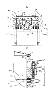
[FIG. 1] FIG. 1 is a diagram showing a vibrating sieve machine according to a
first embodiment of the present invention, including a plan view (a) and a
front view (b)
thereof.
[FIG. 2] FIG. 2 is a diagram showing the vibrating sieve machine of the first
embodiment. including a view (a) thereof taken in a direction indicated by
arrow A of FIG.
1(b) and a cross-sectional view (b) thereof taken along line B-B of FIG. 1(b).
[FIG. 3] FIG. 3 is an enlarged view of a portion C of FIG, 2(b).
[FIG. 4] FIG. 4 is a diagram showing a mesh member used in the vibrating sieve
machine of the first embodiment, including a plan view (a) thereof where a
portion of a sieve
9
CA 03045878 2019-05-28
mesh is cut away. an enlarged view (b) thereof showing a portion D of FIG.
4(a), and a view
(c) thereof taken in a direction indicated by arrow E of FIG. 4(b).
[FIG. 51 Fla 5 is a diagram showing a mesh member frame used in the vibrating
sieve machine of the first embodiment, including a plan view (a) thereof, a
vertical cross-
sectional view (I)) thereof, and a schematic diagram (c) thereof for
describing an operation of
pulling a sieve mesh.
[FIG. 6] FIG. 6 is a diagram showing a mesh replacement operation procedure
(1)
for the vibrating sieve machine of the first embodiment.
[FIG. 71 FIG. 7 is a diagram showing a mesh replacement operation procedure
(2)
for the vibrating sieve machine of the first embodiment.
[FIG. 8] FIG. 8 is a diagram showing a mesh replacement operation procedure
(3)
tiff the vibrating sieve machine of the first embodiment.
[FIG. 9] FIG. 9 is an enlarged cross-sectional view of a main portion of a
vibrating sieve machine according to a second embodiment of the present
invention.
[FIG. 10] FIG. 10 is a diagram showing a mesh member frame used in the
vibrating sieve machine of the second embodiment, including a plan view (a)
thereof a
vertical cross-sectional view (b) thereof and a schematic diagram (e) thereof
for describing an
operation of pulling a sieve mesh.
[FIG. II] FIG. 1 1 is a diagram for describing a conventional technique,
DESCRIPTION OF EMBODIMENTS
[0027]
Specific embodiments of a vibrating sieve machine according to the present
invention will now be described with reference to the accompanying drawings.
Note that the
present invention is in no way intended to be limited to embodiments described
below or
CA 03045878 2019-05-28
COnligurations shown in the drawings.
[0028]
(First Embodiment)
FIG. 1 is a diagram showing a vibrating sieve machine according to a first
embodiment of the present invention, including a plan view (a) and a front
view (b). thereof.
FIG. 2 is a diagram showing the vibrating sieve machine, including a view (a)
thereof taken in
a direction indicated by arrow A of FIG. 1(b) and a cross-sectional view (b)
thereof taken
along line B-B of FIG. l(b).
[0029]
<Overview of Vibrating Sieve Machine>
As shown in FIGS. 1(a) and 1(b), the vibrating sieve machine IA of the first
embodiment is of a vertical type in which the body height can be reduced. lhc
vibrating
sieve machine I A has the function of vibrating and classifying powders of
various materials,
such as medicines, foods, mineral products, metals, and resin raw materials.
The vibrating
sieve machine IA includes a vibrating plate 3 disposed above a supporting
table 2.
[0030]
<Vibrating Plate>
The vibrating plate 3 is a plate-shaped member having a predetermined
thickness
and in the shape of an octagonal ring having an attachment hole for attaching
a sieve
container 6 described below, at a center thereof, as viewed from above. A
plurality of (in
this example, 12) compression coil springs (elastic supports) 4 are provided
between the
vibrating plate 3 and the supporting table 2, and are disposed in a peripheral
direction of the
vibrating plate 3 at predetermined positions. The vibrating plate 3 is
supported and allowed
by the compression coil springs 4 to vibrate.
[0031]
CA 03045878 2019-05-28
A reinforcement plate 5 is provided along an outer peripheral edge of the
vibrating
plate 3. The reinforcement plate 5 is formed by bending a band-shaped plate
material so that
the plate 5 tits the shape of the outer peripheral edge of the vibrating plate
3. The
reinforcement plate 5 is firmly attached to the vibrating plate 3, extending
along substantially
the entire perimeter of the vibrating plate 3. and protruding vertically
downward from the
lower plate surface of the vibrating plate 3. As a result. the stiffness of
the vibrating plate 3
can be improved while an increase in the weight of the vibrating plate 3 is
inhibited.
Therefore, even in the case where a high-power vibrating motor 30 is employed,
the vibrating
plate 3 can be prevented from bending or twisting. Thus, a high-power
vibrating motor 30
can be employed, resulting in an improvement in classification capability.
[0032]
<Sieve Container>
A sieve container 6 is held in the attachment hole of the vibrating plate 3.
The
sieve container 6 includes, as main components, a sieve frame 7 having a
vertical opening
through which powder to be classified is introduced, and a lid 8 that is
removably attached to
an upper opening of the sieve frame 7. An introduction opening 8a for powder
to be
classified is formed at a center portion of the lid 8.
10033]
<Sieve Frame>
As shown in FIGS. 2(a) and 2(b). the sieve frame 7 is formed by fitting
together an
upper separable sieve frame 7a and a lower separable sieve frame 7b. which can
be vertically
separated from each other.
[0034]
As shown in FIG. 2(h), the upper separable sieve frame 7a includes a
cylindrical
upper separable sieve frame body 10 having a vertical opening, a flange II
extending all
12
CA 03045878 2019-05-28
around the upper separable sieve frame body 10 and protruding radially outward
from a lower
end of the upper separable sieve frame body 10, and a tapered flange 12
extending all around
the upper separable sieve frame body 10 and protruding outward and diagonally
upward from
an upper end of the upper separable sieve frame body 10. A circular annular
packing 13 is
attached to the flange 11 of the upper separable sieve frame 7a, extending all
around the upper
separable sieve frame body 10.
[0035]
As shown in FIG. 2(a). a discharge duct 14 is attached to a portion of the
upper
separable sieve frame 7a on one side in the horizontal direction (the left
side in FIG. 2(a)).
projecting from a cylindrical wall surface of the upper separable sieve frame
body 10. The
discharge duct 14 has the function of guiding, to the outside, residual powder
remaining on a
mesh member 40 described below during a classification process.
[0036]
As shown in FIG. 2(b), the lower separable sieve frame 7b includes a lower
separable sieve frame body 20, and a flange 21 extending all around the lower
separable sieve
frame body 20 and protruding radially outward from an upper end of the lower
separable
sieve frame body 20. The flange 21 corresponds to the flange 11 of the upper
separable
sieve frame 7a. A circular annular packing 22 is attached all around the
flange 21 of the
lower separable sieve frame 7b.
[0037]
The lower separable sieve frame body 20 has a cylindrical section 25 in the
shape of
a cylinder having a vertical opening. As shown in FIG. 2(a), a funnel-shaped
chute section
26 that becomes gradually narrower downward is provided below the cylindrical
section 25.
The chute section 26 is integrally fbnned with the cylindrical section 25 so
as to be
continuously connected to the cylindrical section 25. An outlet section 27
through which
13
CA 03045878 2019-05-28
powder in the chute section 26 is dropped and discharged downward is provided
below the
chute section 26. The outlet section 27 is integrally formed with the chute
section 26 so as
to be continuously connected to the chute section 26.
[00381
<Vibrating Motor>
As shown in FIGS. 1(a) and 1(b), the lower separable sieve frame 7b is
provided
with. a beam member 28 penetrating therethrough in the horizontal direction. A
motor
attachment plate 29 is firmly joined to either end of the beam member 28. A
vibrating motor
30 is attached to each motor attachment plate 29. Each vibrating motor 30
generates
vibrations by rotation of eccentric weights provided at opposite ends of the
rotor shaft,
although such a mechanism is not shown and will not be described in detail.
[0039]
As shown in FIG. 2(a), in each vibrating motor 30, an angle 0 between an axial
line
SR of the rotor shaft and a horizontal axial line Si is in the range of 55-65.
In this example,
the axial line SR of the rotor shaft is sloped at 0 = 60 . Note that the
opposite vibrating
motors 30 are disposed so that one vibrating motor 30 and the other vibrating
motor 30 have
opposite phases, i.e.. the images of one vibrating motor 30 and the other
vibrating motor 30
projected onto a vertical plane from the direction of one of opposite sides,
are symmetrical
about a horizontal angle (i.e., one vibrating motor 30 and the other vibrating
motor 30 are
inclined in opposite directions at equal angles). 'Titus, a vibration
component in the vertical
direction can be maximized while a required vibration component in the
horizontal direction
is ensured. A resultant wave motion causes powder on a mesh member 40
described below
to significantly jump upward and strike meshes 43 and 44 described below, so
that powder
particle aggregations are disintegrated or crushed and dispersed. resulting in
a further
improvement in classification capability.
14
CA 03045878 2019-05-28
[00401
<Joint Structure of Lid and Upper Separable Sieve Frame>
As shown in FIG. 2(b), a lid packing 31 is interposed between an outer
peripheral
edge of the lid S and the tapered flange 12 of the upper separable sieve frame
7a to seal an
interstice therebetween with the lid packing 31 supported on a ring plate 32.
A fastening
band 33 is wrapped around a portion where the lid 8 abuts the upper separable
sieve frame 7a.
The fastening band 33 has such a V cross-sectional shape as to bind the outer
peripheral edge
of the lid 8 and the tapered flange 12 of the upper separable sieve frame 7a
together. The
binding by the fastening band 33 can fasten the lid 8 and the upper separable
sieve frame 7a to
each other. When the binding by the fastening band 33 is removed, the lid 8
can be detached
from the upper separable sieve frame 7a.
[0041]
<Mesh Member>
As shown in FIG. 2(b), a mesh member 40 is held between the upper separable
sieve frame 7a and the lower separable sieve frame 7b of the sieve frame 7.
The mesh
member 40 includes, as main components. a mesh member frame 42 and a
reinforcement
mesh 43 constituting a mesh member body 41, a sieve mesh 44, and a fastening
band 45.
[0042]
<Mesh Member Frame>
As shown in FIG. 3, the mesh member frame 42 has an upper circular annular
plate
surface portion 42a, a lower circular annular plate surface portion 42b, an
outer cylindrical.
portion 42c, and an inner cylindrical portion 42d. The mesh member frame 42 is
formed by
bending a polygonal tube material having a quadrangular annular cross-section
into a circular
ring. Thus, the mesh member 40 can easily have a lighter weight, and a
strength such that
the mesh member 40 is not crushed to the extent that the mesh member 40 can no
longer be
CA 03045878 2019-05-28
used, when the mesh member 40 is sandwiched by the separable sieve frames 7a
and 7b.
[0043]
When the mesh member frame 42 is sandwiched by the separable sieve frames 7a
and 7h, the upper circular annular plate surface portion 42a faces the flange
11 of the upper
separable sieve frame 7a. the lower circular annular plate surface portion 42b
faces the flange
21 of the lower separable sieve frame 7b, and the circular annular plate
surface portions 42a
and 42b are sandwiched by the flanges 11 and 2 I of the separable sieve frames
7a and 7b with
the packings 13 and 22 interposed therebetween. Thus, while the entire mesh
member frame
42 is located outside the separable sieve frame bodies 10 and 20, the
reinforcement mesh 43
and the sieve mesh 44, which substantially contribute to sieving and
classification of powder
to be classified, are disposed throughout the interior of the upper and lower
separable sieve
frame bodies 10 and 20. As a result, the effective areas of the reinforcement
mesh 43 and
the sieve mesh 44, which contribute to sieving and classification of powder.
can be
maximized, so that powder to be classified can be more efficiently sieved and
classified. In
addition. the packings 13 and 22 can reliably prevent powder to be classified
from leaking
through an interstice between the separable sieve frames 7a and 7b and the
mesh member 40.
Note that the upper circular annular plate surface portion 42a and the lower
circular annular
plate surface portion 42b correspond to a '-sandwich surface portion- of the
present invention.
[0044]
The outer cylindrical portion 42c joins outer peripheral edges of the upper
circular
annular plate surface portion 42a and the lower circular annular plate surface
portion 42b
together, and faces outward in the radial direction of the separable sieve
frames 7a and 7b.
Meanwhile, the inner cylindrical portion 42d is disposed so as to join inner
peripheral edges
of the upper circular annular plate surface portion 42a and the lower circular
annular plate
surface portion 42b. and face inward in the radial direction of the separable
sieve frames 7a
CA 03045878 2019-05-28
and 7b.
[0045]
As shown in FIG. 5(a), an outer diameter ( D) and an inner diameter (ed) of
the
mesh member frame 42 are set in the range of 400- =1140 min and 352-1080 mm,
respectively.
[0046]
As shown in FIG. 5(b), the mesh member frame 42 is formed in a warped shape.
Specifically, the circular annular plate surface portions 42a and 42b, which
are to be
sandwiched by the flanges 11 and 21 of the separable sieve frames 7a and 7b,
are sloped
upward as one progesses radially outward, i.e. in a direction away from the
center of the
mesh member frame 42. The magnitude of the warpage of the mesh member frame 42
is
defined by a height difference AH between one end and the other end of the
circular annular
plate surface portion 42a, 42b in the radial direction of the mesh member
frame 42. The
height difference AH is set to 0.5-1.5 mm. Note that, for the sake of
convenience. FIG. 5(b)
shows only the height difference AU of the upper circular annular plate
surface portion 42a,
and the magnitude of the warpage of the mesh member frame 42 is defined by
that height
difference. Alternatively, the magnitude of the warpage of the mesh member
frame 42 may
Lie defined by the height difference of the lower circular annular plate
surface portion 42b.
[0047]
When the mesh member frame 42 having such a warpage is sandwiched by the
flanges II and 21 of the separable sieve frames 7a and 7b, the mesh member
frame 42 is
deformed such that the warpage is eliminated. As a result, as shown in FIG.
5(c), the entire
sieve mesh 44 is pulled outward in the radial direction of the mesh member
frame 42 with
appropriate tension, As a result, the sieve mesh 44 that is put on top of the
mesh member
frame 42, covering the reinforcement mesh 43, is tightly attached to the
reinfbrcement mesh
43 without being damaged and with high tension maintained. Therefore, the
sieve mesh 44
17
CA 03045878 2019-05-28
is stably supported by the reinforcement mesh 43. and thereby exhibits
sufficient
classification performance.
[0048]
<Reinforcement Mesh>
As shown in FIG. 4(a). the reinforcement mesh 43 stretches across the mesh
member frame 42 to block the opening of the mesh member frame 42, and is
firmly joined to
an upper edge of the inner cylindrical portion 42d by a firmly joining means
such as seam
welding with the reinforcement mesh 43 stretching across the opening of the
mesh member
frame 42. The reinforcement mesh 43 may, for example, be a stainless-steel
mesh having a
relatively coarse mesh size.
[0049]
<Sieve Mesh>
The sieve mesh 44 is put on top of the mesh member body 41, covering the
reinforcement mesh 43 and hanging down over an outer peripheral surface of the
mesh
member frame 42 from above the reinforcement mesh 43. The sieve mesh 44 may.
for
example, be a sheet-shaped nylon mesh having a mesh size finer than that of
the
reinfbreement mesh 43 (may, of course, be a stainless-steel mesh). The sieve
mesh 44 is tied
and fixed to the mesh member body 41 by the fastening band 45 wrapped around
the outer
peripheral surface of the mesh member frame 42 (the outer cylindrical portion
42c) fastening
the sieve mesh 44 to the mesh member body 41 with the sieve mesh 44 interposed
therebetween. The sieve mesh 44 is removably attached to the mesh member body
41 so
that by; loosening the fastening band 45, the sieve mesh 44 can be removed
from the mesh
member body 41.
[0050]
Thus. the reinforcement mesh 43, which stretches across the mesh member frame
18
CA 03045878 2019-05-28
42, functions as a reinforcing material that supports the sieve. mesh 44 from
below. The
sieve mesh 44 that is removably attached to the mesh member body 41, covering
the
reinforcement mesh 43, functions as a mesh that substantially contributes to a
powder
classification process. Therefore, the function of the mesh member 40 can be
recovered only
by replacing the sieve mesh 44, i.e. it is easy to perform mesh replacement.
[0051]
<Fastening Band>
As shown in FIGS. 4(b) and 4(e), the fastening band 45 includes a band member
46
and a band diameter adjustment mechanism 47.
[0052]
<Band Member>
The band member 46 is formed in a ring shape by bending so that the band
member
46 can be wrapped around the outer peripheral surface of the mesh member frame
42 (outer
cylindrical portion 42c) with the sieve mesh 44 interposed therebetween. The
band member
46 is made of, for example, a metal material, such as stainless steel.
[0053]
<Band Diameter Adjustment Mechanism>
The band diameter adjustment mechanism 47 is attached to an outer peripheral
surface of the band member 46. The band diameter adjustment mechanism 47
includes a
housing 48, a spindle 49, and a plurality of worm grooves 50. The band
diameter adjustment
mechanism 47 has the function of adjusting a hand diameter of the band member
46. Here,
the housing 48 is attached to one end (first end) of the band member 46. The
spindle 49 has
a shaft that is rotatably supported on the housing. The shaft has worm teeth
(not shown)
around an outer periphery thereof. The worm teeth are disposed inside the
housing 48.
The worm grooves 50 are provided at the other end (second end) of the band
member 46, and
19
CA 03045878 2019-05-28
are formed so as to engage with the worm teeth of the spindle 49.
[0054]
In the band diameter adjustment mechanism 47. the second end of the band
member
46 is inserted into the housing 48, and the spindle 49 is operated to cause
the worm teeth of
the spindle 49 to engage with the worm grooves 50, so that the fastening band
45 is allowed
to act on the mesh member frame 42. In this situation, when the spindle 49 is
rotated in a
manner like fastening a bolt, the spindle 49 is screwed down by the worm teeth
thereof
engaging with the worm grooves 50 so that the second end of the band member 46
moves
along the first end thereof, and therefore, the diameter of the band member 46
is reduced.
As a result, an object to be tied (in this example, the sieve mesh 44) that is
provided inside the
band member 46 is fastened. Thus, even if a sieve mesh 44 having a different
mesh or wire
diameter is used, the sieve mesh 44 can be easily tied and fixed to the mesh
member frame 42
by the fastening band 45.
[0055]
In the hand diameter adjustment mechanism 47. by operating the spindle 49 so
as to
disengage the worm teeth of the spindle 49 from the worm grooves 50. the
fastening band 45
can be removed from the mesh member frame 42.
[0056]
<Joint Structure of Upper Separable Sieve Frame and Lower Separable Sieve
Frame>
As Shown in FIGS. 2(a) and 2(b), a plurality of hook brackets 60 are provided
on an
outer peripheral surface of the upper separable sieve frame 7a at
predetermined intervals in a
peripheral direction of the upper separable sieve frame 7a, protruding from
the outer
peripheral surface of the upper separable sieve frame 7a. Each hook bracket 60
includes a
reception opening 60a that is open outward in the radial direction of the
upper separable sieve
CA 03045878 2019-05-28
frame 7a, and a pair of hook. portions 60b provided on the opposite sides of
the reception
opening 60a.
[0057]
Swing bolts 61 are provided on an upper surface of the vibrating plate 3. Each
swing bolt 61 can be swung between a horizontal position in which the swing
bolt 61 is laid
on the vibrating plate 3 and a vertical position in which the swing bolt 61
spans between the
vibrating plate 3 and the hook bracket 60. The upper separable sieve frame 7a
and the lower
separable sieve frame 7b are fastened together by a nut 62 screwing onto the
swing bolt 61 in
the vertical position and sitting on the hook bracket 60.
[0058]
Thus, the upper separable sieve frame 7a and the lower separable sieve frame
7b are
reliably fastened together by fastening the nut 62 to the swing bolt 61.
Therefore, even if the
amplitude in the vertical direction increases due to the use of the high-power
vibrating motor
30, the joint portion of the upper separable sieve frame 7a and the lower
separable sieve frame
is 7b can be prevented from becoming loose, and the loss of the vibrating
motion in the vertical
direction due to the looseness can be prevented. Even if the nut 62 is
fastened to the swing
bolt 61 with the sieve mesh 44 sticking out of a portion where the upper
separable sieve frame
7a and the lower separable sieve frame 7b abut each other, the swing bolt 61
does not bite into
the sieve mesh 44 to damage the sieve mesh 44, because the swing bolt 61 is
not in direct
contact with the abutting portion and is not fastened to the abutting portion.
and an axial force
is indirectly applied from the swing bolt 61 to the abutting portion through
the upper
separable sieve frame 7a and the lower separable sieve frame 7b.
[0059]
<Mesh Replacement Operation>
Next, an operation of attaching the sieve mesh 44 involved in a mesh
replacement
21
CA 03045878 2019-05-28
operation 1ir recovering the function of the mesh member 40 in the vibrating
sieve machine
IA of the first embodiment, will be described.
[0060]
Initially, as shown in FIG. 6(a). the mesh member body 41 is placed on the
packing
22 attached to the flange 21 of the lower separable sieve frame 7b with the
mesh member
frame 42 concentric with the lower separable sieve frame body 20 (see FIG.
2(b)).
[0061]
Next, as shown in FIGS. 6(a) and 6(b), the sieve mesh 44 is put on top of the
reinforcement mesh 43 of the mesh member body 41. The fastening band 45 is
wrapped
around the outer peripheral surface of the mesh member frame 42 so as to
sandwich the sieve
mesh 44 hanging down over the outer peripheral surface of the mesh member
frame 42 (see
FIG. 6(a)µ) from above the reinforcement mesh 43, between the fastening band
45 and the
mesh member frame 42. As shown in FIGS. 6(b) and 7(a), the spindle 49 of the
band
diameter adjustment mechanism 47 is rotated in a manner like fastening a bolt.
using a
fastening tool 65, so as to reduce the diameter of the band member 46 of the
fastening hand 45
and thereby fasten the sieve mesh 44, so that the sieve mesh 44 is tied and
fixed to the mesh
member body 41 (the mesh member frame 42). Note that an excess portion of the
sieve
mesh 44 that sticks out of the fastening band 45 is cut as appropriate, or is
folded up and then
put into the interior of the upper separable sieve frame 7a when the upper
separable sieve
frame 7a is placed in an operation described below.
[0062]
Next, as shown in FIG. 7(b), the upper separable sieve frame 7a is placed on
the
mesh member 40 such that the packing 13 attached to the flange 11 of the upper
separable
sieve frame 7a abuts the mesh member frame 42 with the sieve mesh 44
interposed
therebetween, and the upper separable sieve frame body 10 is concentric with
the mesh
CA 03045878 2019-05-28
member frame 42.
[0063]
Next, as shown in FIGS. 8(a) and 8(b). the swing bolts 61 are successively
swung
into the vertical position and are thereby hooked on the respective hook
brackets 60. The
nuts 62 are screwed onto and fastened to the respective swing bolts 61, and
sit on the
respective hook brackets 60. The nuts 62 sitting on the hook brackets 60 are
further
fastened, so that axial threes are indirectly applied from the swing bolts 61
to the abutting
portion of the upper separable sieve frame 7a and the lower separable sieve
frame 7b through
the separable sieve frames 7a and 7b, and the upper separable sieve frame 7a
and the lower
separable sieve frame 7b are thereby fastened together. Thus, the operation of
attaching the
sieve mesh 44 involved in the mesh replacement operation is completed, and the
vibrating
sieve machine IA is ready to be used. At this time, the band diameter
adjustment
mechanism 47 may be positioned to interfere with a member around the sieve
frame 7 such as
the swing bob 61 when the vibrating sieve machine IA is actuated. In this
case, it is not
necessary to disassemble the sieve frame 7 and rearrange the mesh member 40 so
that the
band diameter adjustment mechanism 47 does not interfere with the swing bolt
61, which is a
complicated operation. Instead, only the fastening band 45 is removed from the
mesh
member frame 42 by operating the spindle 49 so as to disengage the worm teeth
of the spindle
49 from the worm grooves 50 in the band diameter adjustment mechanism 47, and
the band
diameter adjustment mechanism 47 is rearranged and attached again so as not to
interfere with
the swing bolt 61. Thus, the band diameter adjustment mechanism 47 can be
easily
prevented from interfering with the swing bolt 61,
[0064J
<Operation of Classification Process>
Powder to be classified is placed inside the upper separable sieve frame 7a of
the
CA 03045878 2019-05-28
vibrating sieve machine IA that is ready to be used after the sieve mesh 44 is
attached thereto.
Next. the lid 8 is attached to the upper separable sieve frame 7a, and both of
them are fastened
together by the fastening hand 33. Thereafter, the opposite vibrating motors
30 are
synchronously driven to apply vibrations to the powder to be classified that
is placed on the
mesh member 40 for sieving and classification.
[0065]
A vibration component in the vertical direction and a vibration component in
the
.horizontal direction are transmitted from the vibrating motors 30 to the
sieve container 6. A
wave motion generated by the vertical and horizontal vibrating motions of the
sieve container
6 causes the powder on the mesh member 40 to significantly jump up and strike
the meshes
43 and 44. As a result, powder particle aggregations are disintegrated or
crushed and
dispersed. The powder passed through the sieve mesh 44 by the classification
process is
discharged out through the outlet section 27 of the lower separable sieve
frame 7b.
Meanwhile. residual powder remaining on the sieve mesh 44 is discharged
through the
discharge duct 14 to the outside.
[0066]
In the vibrating sieve machine IA of the first embodiment, the mesh member
frame
42 is sandwiched by the separable sieve frames 7a and 7b with the outer
peripheral surface of
the mesh member frame 42 exposed outward in the radial direction of the
separable sieve
frames 7a and 7b. Therefore, compared to the conventional vibrating sieve
machine 100 in
which the mesh member frame 104, which does not substantially contribute to
sieving and
classification of powder to be classified, is entirely disposed inside the
sieve frame 101 (the
upper separable sieve frame 101a) (see FIG. II), the effective areas of the
reinforcement
mesh 43 and the sieve mesh 44, which substantially contribute to powder
sieving and
classification, increase, and the fastening band 45 attached to the outer
peripheral surface of
24
CA 03045878 2019-05-28
the mesh member frame 42 is exposed outward in the radial direction of the
separable sieve
frames 7a and 7b. Therefore, powder to be classified can be more efficiently
sieved and
classified than in the conventional art, and the mesh member 40 and the sieve
frame 7 can be
fitted together without the fastening band 45 interfering with the sieve frame
7.
[0067]
(Second Embodiment)
FIG. 9 is an enlarged cross-sectional view of a main portion of a vibrating
sieve
machine according to a second embodiment of the present invention. HG. 10 is a
diagram
showing a mesh member frame used in the vibrating sieve machine of the second
embodiment, including a plan view (a) thereof, a vertical cross-sectional view
(b) thereof, and
a schematic diagram (c) thereof for describing an operation of pulling a sieve
mesh. Note
that parts of the vibrating sieve machine of the second embodiment that are
the same as or
similar to those of the vibrating sieve machine of the first embodiment are
indicated by the
same reference characters and will not be described in detail. Parts specific
to the vibrating
sieve machine of the second embodiment will now be mainly described.
[0068]
As shown in FIG. 9, in the vibrating sieve machine I B of the second
embodiment. a
mesh member 70 includes a mesh member body 71 having a circular annular mesh
member
frame 72 and a reinforcement mesh 43 stretching across the frame 72. Here, the
mesh
member frame 72 has a circular annular plate surface portion 72a sandwiched by
flanges 11
and 21 of separable sieve frames 7a and 7b. and an outer cylindrical portion
72c protruding
downward from an outer peripheral edge of the circular annular plate surface
portion 72a.
The mesh member frame 72 is formed by bending an equal-angle steel (angle
material)
having an L-shaped cross-section into a circular ring, and welding the
opposite ends of the
steel together. Thus, the circular annular plate surface portion 72a, whose
structure does not
CA 03045878 2019-05-28
have a hollow portion, is sandwiched by the flanges II and 21 of the separable
sieve frames
7a and 7b so that the mesh member 70 is fixed to the sieve frame 7. Therefore.
when the
mesh member 70 is fixed to the sieve frame 7. the mesh member frame 72 can be
reliably
prevented from being crushed and deformed to the extent that the mesh member
70 can no
longer be used. As a result, the tension of the sieve mesh 44 tied and fixed
to the mesh
member frame 72 can be prevented from being reduced due to the deformation of
the mesh
member frame 72. Note that the circular annular plate surface portion 72a
corresponds to
the "sandwich surface portion- of the present invention.
[0069]
As shown in FIG. 10(a). the mesh member frame 72 has an outer diameter (0D) in
the range of 400-1140 mm, and an inner diameter (0d) in the range of 352-1080
mm.
[0070]
As shown in FIG. 10(b), the mesh member frame 72 is formed in a warped shape.
Specifically, the circular annular plate surface portion 72a, which is to be
sandwiched by the
flanges 11 and 21 of the separable sieve frames 7a and 7b. is sloped upward as
one progresses
radially outward, i.e. in a direction away from the center of the mesh member
frame 72. The
magnitude of the warpage of the mesh member frame 72 is defined by a height
difference AH
between one end and the other end of the circular annular plate surface
portion 72a in the
radial direction of the mesh member frame 72. The height difference AH is 0.5--
1.5 mm.
[0071]
When the mesh member frame 72 having such a warpage is sandwiched by the
flanges 11 and 21 of the separable sieve frames 7a and 7b. the mesh member
frame 72 is
&tinned such that the warpage is eliminated. As a result, as shown in FIG.
10(c), the entire
sieve mesh 44 is pulled outward in the radial direction of the mesh member
frame 72 with
appropriate tension. As a result, the sieve mesh 44 that is put on top of the
mesh member
26
CA 03045878 2019-05-28
frame 72, covering the reinforcement mesh 43. is tightly attached to the
reinfbreement mesh
43 without being damaged and with high tension maintained. Therefore. the
sieve mesh 44
is stably supported by the reinforcement mesh 43, and thereby exhibits
sufficient
classification performance. Thus, the vibrating sieve machine 1B of second
embodiment has
an advantageous effect similar to that of the vibrating sieve machine IA of
the first
embodiment.
INDUSTRIAL APPLICABILITY
[0072]
The vibrating sieve machine of the present invention can more efficiently
sieve and
classify powder to he classified than in the conventional art. In addition.
the mesh member
and the sieve frame can be fitted together without the fastening band
interfering with the sieve
frame. Therefore, the vibrating sieve machine of the present invention is
suitably useful for
classification process applications of powders of various materials, such as
medicines, foods.
mineral products, metals, and resin raw materials.
REFERENCE SIGNS LIST
[0073]
I A. I B vibrating sieve machine
7 sieve frame
7a upper separable sieve frame
7b lower separable sieve frame
10 upper separable sieve frame body
11 flange
13 packing
27
CA 03045878 2019-05-28
20 lower separable sieve frame body
21 flange
22 packing
40 mesh member
41 mesh member body
42 mesh member frame
42a upper circular annular plate surface portion (sandwich surface
portion)
42h lower circular annular plate surface portion (sandwich surface
portion)
42c outer cylindrical portion
42d inner cylindrical portion
43 reinforcement mesh
44 sieve mesh
45 fastening hand
46 band member
47 band diameter adjustment mechanism
48 housing
49 spindle
50 worm groove
70 mesh member
71 mesh member body
72 mesh member frame
72a circular annular plate surface portion (sandwich surface portion)
72c outer cylindrical portion
=
28