Note: Descriptions are shown in the official language in which they were submitted.
CA 03045942 2019-05-06
=
DEVICE FOR REMOVING ORGANS FROM A HUMAN OR ANIMAL BODY
The invention relates to a device for removing organs from a human or animal
body.
A device of this type serves in the removal of inner organs that have suffered
in
particular as a result of diseases or other negative effects and can no longer
properly
perform their function or have suffered necrosis. In particular, a device of
this nature is
intended to remove a pathological uterus. Many of the devices of the above-
mentioned
type work in an endoscopic manner and comprise at least two endoscopes, one of
which
comprises forceps to sever the organ to be removed. However, when using these
prior-
art devices, it was not possible, or required extreme effort, to create
sterile surroundings
in the body in the area of the organ to be removed, so that remnants and
residual
particles of the removed organ remained in the body, which led to an undesired
contamination within the body. The problem with these prior-art devices in
particular
results from the severed organ falling into the body section below it due to
gravity, which
not only favours contamination but also leads to sterility problems.
One objective of the present invention is to present an improved device of the
above-
.. mentioned type that aids in easily creating a substantially sterile
environment within the
body in the area of the organ to be removed and further makes it possible to
substantially prevent a contamination with remnants and residual particles of
the
removed organ.
This objective is met by the invention with a device for removing organs from
the human
or animal body, with a tube that comprises a proximal end and a distal end and
is
intended to be partially introduced into the body with its proximal end,
whereby the distal
end of the tube can be connected to a suction air source and the proximal end
of the
tube is embodied for a suctional engagement with the organ to be removed, said
device
comprising a tubular casing at least sectionally enclosing the tube that
possesses a
proximal end and a distal end, by which it is attached to the tube, further
comprising a
handling device, which preferably is arranged and embodied at the tube, in
order to
CA 03045942 2019-05-06
2.
open or extend the tubular casing at its proximal end, to guide or place it
around the
organ, and comprising a closing device, which is embodied to close the
proximal end of
the tubular casing, and a comminuting device, which is provided within the
tube,
preferably in the area of its proximal end.
The invention's use of a tubular casing, which at its proximal end is at first
opened or
extended, subsequently is guided or placed around the organ, and finally is
closed at its
proximal end, makes it possible to securely and completely enclose the organ
to be
removed in a simple manner, which to the highest degree possible achieves the
required
sterility and at the same time prevents contamination with remnants or
residual particles
of the organ to be removed. According to the invention, this is achieved with
a handling
device, which is arranged and embodied at a tube to be inserted into the body,
and is
designed to open or extend the tubular casing at its proximal end, to guide or
place the
tubular casing around the organ, and with a closing device that is embodied to
close the
proximal end of the tubular casing. The term "arranged at the tube" may also
refer to a
position of the handling device along the tube and/or adjacent to the tube, as
well as an
arrangement without being attached to the tube. After closing the proximal end
of the
tubular casing by means of the closing device, the tubular casing assumes the
shape of
a pouch, which now accommodates the organ to be removed.
The invention also provides a simple but effective solution for the removal of
the organ
to be eliminated from the body, which meets the stringent requirements for
necessary
sterility. In this regard, the invention intends that the distal end of the
tube can be
connected to a suction air source and the proximal end of the tube is embodied
for a
suction engagement with the organ to be removed, as a result of which the
organ to be
removed, which is entrapped in a bag-like manner by the tubular casing
connected to
the tube's proximal end and is consequently separated from the surroundings,
i.e. the
rest of the body, is sucked into the proximal end of the tube. The invention
further
provides a comminuting device, which is arranged and embodied within the tube
in the
area of its proximal end, for the purpose of comminuting the organ to be
removed, while
it is drawn into the proximal end of the tube by the suction air source. The
comminuting
CA 03045942 2019-05-06
* Y
3
reduces the volume of the organ to be removed and consequently also the volume
of the
closed tubular casing that accommodates the organ in the way of a pouch, which
improves the ease with which the organ to be removed can be withdrawn through
the
tube.
At this point it should be mentioned that the term "proximal", which according
to the
German Duden dictionary means "closer to the centre of the body" and the term
"distal",
which according to the German Duden dictionary means "further from the center
of the
body", in the present context refer to the position relative to the organ to
be removed
within the body prior to the organ's removal.
Preferred embodiments and further developments of the invention are described
in the
dependent claims.
Consequently it is practical to arrange the handling device relative to the
tube moveable
along the latter's longitudinal direction between an extended proximal final
position and
a retracted distal final position, whereby in a preferred further development,
the handling
device is also arranged moveable along the transverse direction of the tube,
in order to
effectively place the tubular casing around the organ in dependence on the
respective
position of the organ to be removed.
A particularly preferred design of the handling device is characterized in
that it
comprises opposingly situated gripping arms, each of which possesses a
proximal end
and a distal end, and which are embodied to releasably grip the tubular
casing,
preferably in the region of the latter's proximal end.
Advantageously, the gripping arms comprise, preferably in the region of their
proximal
ends, securing means that are embodied to detachably secure the tubular
casing,
preferably at its proximal end, to the gripping arms.
Expediently, the gripping arms are aligned along the longitudinal direction of
the tube.
CA 03045942 2019-05-06
=
4
Preferentially, the gripping arms are embodied to be elastic and are arranged
at an
angle, preferably for example transversely, to the longitudinal extent of the
tube. In a
preferred further development, in the relaxed state of the gripping arms, the
proximal
ends of the respectively opposing gripping arms are separated by a distance
that is less
than the diameter of the tube, and a central section of the gripping arms,
situated
between the proximal and the distal ends, is curved outward with respect to
the tube, so
that at least at the location that is furthest outward along the radial
direction, the distance
of the central sections to respective opposing gripping arms is greater than
the distance
between the proximal ends of said gripping arms, and preferably also greater
than the
diameter of the tube. Such a shape of the gripping arms is particularly
advantageous,
not only to guide or place the tubular casing around the organ, but also to
securely hold
the organ enclosed by the closed tubular casing in the region of the central
sections of
the gripping arms. Further, the elasticity in combination with the shape also
ensures that
the gripping arms are at first opened at their proximal end against the force
exerted by
the elasticity, which results in an opening or widening of the tubular casing
at its
proximal end, and that subsequently the pretension generated by the elasticity
is used to
bring the proximal ends of the gripping arms back to their closed position
after the organ
has been enclosed.
In a further preferred embodiment, the exterior side of the tube is equipped
along its
longitudinal direction with guide grooves, in which the gripping arms are
accommodated
moveable along the grooves' longitudinal direction, and the arrangement is
designed so
that in the proximal final position of the handling device, the gripping arms
extend
beyond the proximal end of the tube with a portion connected to their proximal
ends and
thus are exposed. This facilitates an especially large range of motion for the
gripping
arms.
The handling device preferably comprises spreading elements, which are
embodied so
that they at least partially spread apart the gripping arms to their proximal
final position
during the movement of the handling device, in order to open or extend the
tubular
casing at its proximal end and to guide or place it around the organ.
CA 03045942 2019-05-06
In a preferred further development of this embodiment, the spreading elements
are
arranged at the tube in the area of its proximal end and possess a guide
surface, which
rises between the exterior side of the tube and the latter's proximal end, and
to which
the gripping arms may be brought in contact with. Thus the radial distance of
the guide
5 surfaces of the spreading elements at their proximal ends or at the
proximal end of the
tube is greater than the tube radius, and consequently the radial separation
between the
guide surfaces of opposing spreading elements at their proximal ends or at the
proximal
end of the tube is greater than the tube diameter. Consequently, the spreading
elements of this preferred further development act in a cone-like manner to
spread the
gripping arms in contact with them. If guide grooves extending along the
longitudinal
direction are embodied on or in the exterior side of the tube, the spreading
elements
may preferentially be arranged in these guide grooves and their guide surfaces
may rise
from the bottom of the guide grooves.
In a preferred further development, the spreading elements are arranged
separated by
some distance, one spreading element is associated with each gripping arm, and
for the
purpose of releasing the gripping arms from the spreading elements, the tube
on the one
hand and/or the gripping arms on the other hand can be subjected to a relative
motion
with respect to each other, in order to deliver the gripping arms into a
position laterally
next to the spreading elements. Thus, a lateral displacement of the tube
relative to the
gripping arms or a lateral displacement of the gripping arms relative to the
tube or a
corresponding joint lateral displacement of the tube and the gripping arms
relative to
each other causes the gripping arms to slide off the spreading elements, and
thus the
closing of the gripping arms.
Preferably the gripping arms are connected to each other in the area of their
distal ends,
which simplifies the handling of the gripping arms, in particular during their
movement
into the proximal end position. An advantageous further development comprises
an
annular element, to which the gripping arms are mounted at their distal end,
and which
preferably can be used as a handling element. The closing device expediently
is
provided at the handling device. If gripping arms are employed, then the
closing device
CA 03045942 2019-05-06
6
preferably comprises closing means, which are provided at the gripping arms,
preferably
at their exposed i.e. proximal ends. Further, the closing device can
preferably comprise
eyes or eyelets provided at the proximal end of the tubular casing as well as
at least one
thread or wire that can be threaded through the eyes or eyelets, as a result
of which the
closing process of the proximal end of the tubular casing takes place in the
manner of a
sewing process.
To provide for a particularly effective comminuting of the organ to be
removed, the
comminuting device preferably comprises at least one rotatably supported
cutting blade.
A sleeve preferably is provided to be arranged on the body surface or to be
inserted into
the body surface, whereby the tube extends through the sleeve and is moveable
relative
to the sleeve. A sleeve of this type facilitates fixing the device in position
on the surface
of the body and also allows a simpler and more accurate alignment of the tube
when the
latter is inserted into the body in the direction of the organ to be removed.
If gripping arms are included, the gripping arms preferentially are arranged
between the
inner side of the sleeve and the exterior side of the tube, and are in contact
with the
inner side of the sleeve and the exterior side of the tube. An arrangement of
this type
facilitates a reliable guiding of the gripping arms. If the gripping arms are
embodied with
a central section with an outwardly curved shape that is located between the
proximal
and the distal ends, then this arrangement results in a spreading due to the
curved
.. shape of the gripping arms. In the retracted distal final position of the
handling device, in
which the gripping arms are in their so-called starting position, the gripping
arms are
forced by the sleeve into a substantially completely extended state and
consequently are
substantially completely stretched, since the interspace between the exterior
side of the
tube and the inner side of the sleeve does not provide any substantial room
for
movement; consequently this state can also be referred to as a forced
constraint, which
arises out of the mentioned configuration and does not provide the gripping
arms with
any other choice but to assume a completely extended shape. When the handling
device is moved in the direction towards its proximal final position, and the
gripping arms
CA 03045942 2019-05-06
7
correspondingly are extended, then the curved shape of the central section of
the
gripping arms at first causes the gripping arms to spread apart, at least for
as long as
the curved shape of the outwardly curved central section of the gripping arms
contributes to generating a force that pushes the central section of the
gripping arms
outward towards the inner side of the sleeve, and subsequently a closing of
the gripping
arms again, no later than when the outwardly curved central section of the
gripping arms
is exposed outside of the sleeve and thus when the gripping arms no longer are
subject
to any force effects from the sleeve.
In a preferred further development, the inner side of the sleeve is equipped
with guide
grooves, which extend along the direction of movement of the handling device,
and in
which the gripping arms are arranged moveable along the grooves' longitudinal
direction, and the arrangement is designed so that in the proximal final
position of the
handling device, the gripping arms with their section adjoining to their
proximal end
project beyond the proximal end of the tube and consequently are exposed.
The sleeve preferably possesses a flange-like rim to facilitate a reliable
bearing contact
on the surface of the body.
In a further preferred embodiment, the tubular casing is embodied as a double
casing
with an inner casing and an outer casing, which surrounds the inner casing at
a distance
while forming an interspace, and a pressurized air source can be connected to
the
interspace formed between the inner casing and the outer casing. Connecting a
pressurized air source facilitates inflating and pressurizing the interspace
between the
inner casing and the outer casing. This has three effects. A larger space is
created
around the organ to be removed, which facilitates the handling of the device
and in
particular that of the handling device. Furthermore, the in-body surroundings
of the
organ to be removed are being stabilized. Finally, and this is a very
important aspect,
the organ to be removed is pressurized, which effects a compression of the
organ, which
in turn, acting in addition to the underpressure prevalent there due to the
suction action,
speed up and thus promotes the removal of the organ through the tube.
CA 03045942 2019-05-06
8
In this embodiment, the closing device may be embodied for closing the
proximal end of
the inner casing and for closing the proximal end of the outer casing or
alternatively for
jointly closing the proximal ends of the inner casing and the outer casing.
In a further preferred further development of this embodiment, the handling
device is at
least partially arranged in the interspace formed between the inner casing and
the outer
casing. This prevents the organ to be removed from coming into contact with
the
handling device and ensures a reliable handling of the tubular casing for
enclosing the
organ.
In a further preferred further development of this embodiment the inner casing
is
connected in a sealing manner to the outer casing at the proximal end of the
tubular
casing. This further development is particularly advantageous since the
closing device
has to close the common proximal end of the tubular casing formed by the inner
casing
and the outer casing in a single operating cycle. A further advantage is
realized if at
least some sections of the handling device are arranged in the interspace
between the
inner casing and the outer casing, because the handling device with its
proximal end
comes into bearing contact from the inside to the proximal end of the tubular
casing that
connects the inner casing with the outer casing in a sealing manner and
consequently
the tubular casing can be particularly easily handled with the help of the
handling device.
This in particular applies when gripping arms are employed, over which the
tubular
casing embodied as a double casing can be pulled in the manner of a sock.
In a further particularly preferred embodiment, the tube is embodied as in
inner tube,
which is encompassed by an outer tube with an interspace formed between them;
the
inner tube is arranged moveable relative to the outer tube, and in this is
arranged so that
the section adjacent to its proximal end can be extended from the proximal end
of the
outer tube; the tubular casing prior to its use is substantially arranged in
the interspace
between the inner tube and the outer tube and can be exposed by extracting the
inner
tube from the outer tube; and the comminuting device is provided in the inner
tube in the
area of the latter's proximal end. Consequently this embodiment of the
invention
CA 03045942 2019-05-06
9
facilitates 'hiding' the tubular casing prior to its deployment in the
interspace between the
inner tube and the outer tube, so that it only is deployed after the device
has been
introduced into the body by pulling the inner tube from the outer tube.
When using the above-mentioned sleeve, the sleeve preferably is arranged at
the
proximal end of the outer tube or is even formed by the outer tube itself.
Furthermore, the handling device can be arranged and embodied either at the
exterior
side of the inner tube or at the outer tube, in dependence on the space
requirements of
the device.
Expediently, the tubular casing should be attached by its distal end to the
inner tube,
since the disposal of the organ to be removed takes place through the inner
tube.
Prior to deployment of the device, the inner tube usually is retracted in the
outer tube
and the handling device is also in a retracted position, in which it at least
does not
protrude beyond the outer tube and the inner tube. During the extraction of
the inner
tube from the outer tube, preferably at first the handling device is taken
along by the
inner tube or the handling device is moved substantially in parallel to the
inner tube,
whereby the handling device takes along the tubular casing and pulls at least
the greater
portion of the latter from the interspace originally formed between the inner
tube and the
outer tube and thus removes it from the outer tube, until the proximal end of
the inner
tube is situated in proximity to the organ to be removed or even has come into
contact
.. with the latter. Preferably, the handling device is subsequently moved
relative to the
inner tube, in order to open or extend the proximal end of the tubular casing
taken along
by the handling device, and to guide or place it around the organ to be
removed.
Alternatively or supplementary it can also be envisioned that in a further
development of
the above-mentioned embodiment the inner tube is embodied in a way so that
during its
extraction from the outer tube it takes along the tubular casing and
substantially exposes
the latter.
CA 03045942 2019-05-06
If the tubular casing is embodied as a double casing, the inner casing
preferably can be
fastened to the inner tube while the outer casing is fastened to the outer
tube, and the
pressurized air source can be connected to the interspace formed between the
inner
tube and the outer tube. Thus, not only is it particularly simple and
simultaneously
5 reliable to connect the pressurized air source to the device outside of
the body, but the
pressurized air is also delivered in a simple yet effective manner into the
tubular casing,
which is embodied as a double casing, inside the body.
Preferred embodiment examples are explained in the following with the help of
the
figures. The figures show:
10 Fig. 1 shows a schematic longitudinal sectional view of a device to
remove organs from
the human or animal body in accordance with a first preferred embodiment in
an initial first operating state;
Fig. 2 shows a schematic longitudinal sectional view of the device of Fig. 1
in a second
operating state, in which the device is already in contact with the organ to
be
removed;
Fig. 3 shows in a schematic longitudinal sectional view an enlarged partial
view of the
device of Fig. 1 in a third operating state;
Fig. 4 shows in a schematic longitudinal sectional view an enlarged partial
view of the
device of Fig. 1 in a fourth operating state;
Fig. 5 shows in a schematic longitudinal sectional view an enlarged partial
view of the
device of Fig. 1 in a fifth operating state, now with the organ to be removed
completely enclosed by a tubular casing;
CA 03045942 2019-05-06
11
Fig. 6 shows in a schematic longitudinal sectional view an enlarged partial
view of the
device of Fig. 1 in a sixth operating state, with the organ to be removed
completely enclosed by the tubular casing;
Fig. 7 shows in a schematic longitudinal sectional view an enlarged partial
view of the
device of Fig. 1 in a seventh operating state, with the organ substantially
removed from the body;
Fig. 8 shows a schematic longitudinal sectional view of the device of Fig. 1
in an eighth
operating state where it is substantially completely removed from the body;
Fig. 9 shows schematically in an enlarged partial perspective view a sleeve
and the
proximal ends of gripping arms forming at least a part of a handling device,
in
a still closed position as part of a device to remove organs from the human or
animal body in accordance with a second preferred embodiment;
Fig. 10 shows substantially the same view as Fig. 9, but with the gripping
arms in a
slightly opened state;
Fig. 11 shows substantially the same view as Fig. 9, but with the gripping
arms in a
completely spread, i.e. opened state;
Fig. 12 shows in a schematic perspective view at least part of a handling
device with
gripping arms as part of a device for removing organs from the body of
human or animal, in accordance with a third preferred embodiment;
Fig. 13 shows a lateral view of the shape of a gripping arm of the first
embodiment of
Fig. 12; and
Fig. 14 shows a schematic perspective lateral view of at least part of a
handling device
with gripping arms as part of a device in accordance with a fourth preferred
CA 03045942 2019-05-06
12
embodiment, whereby Fig. 14a shows the handling device according to the
second embodiment in its entirety, and Fig. 14b shows a section in the area
of the proximal end of an inner tube.
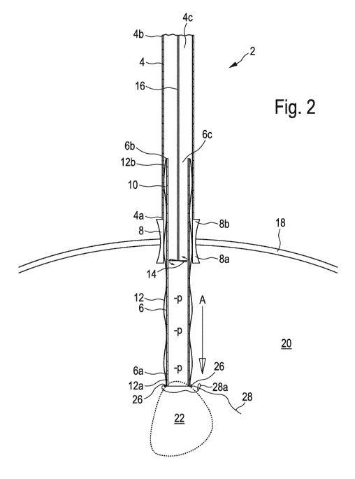
Fig. 1 shows in a schematic longitudinal sectional view a device 2 for
removing organs
from the human or animal body according to a first preferred embodiment
example, in an
initial first operating state.
The device 2 comprises an outer tube 4 with an open proximal end 4a and an
open
distal end 4b, as well as an inner tube 6 with an open proximal end 6a and an
open
distal end 6b. In the shown embodiment example, the device 2 further comprises
a
sleeve 8, which comprises an open proximal end 8a and an open distal end 8b,
and
which forms an extension of the outer tube 4, since the outer tube 4 with its
proximal end
4a is attached to the distal end 8b of the sleeve 8. Relative to the
arrangement of outer
tube 4 and sleeve 8, the inner tube 6 is supported moveable along the
arrangement's
longitudinal direction, for which purpose corresponding suitable support or
guide
elements must be provided, which however are not shown in the figures. Between
the
inner side of the outer tube 4 and the sleeve 8 on the one hand and the
exterior side of
the inner tube 6 on the other extends an interspace with an annular cross-
section, which
in the initial first operating state shown in Fig. 1accommodates a tubular
casing 12. In
the shown embodiment example, the device 2 further comprises a comminuting
device,
which comprises a blade, which is arranged in the area of the proximal end 8a
of the
sleeve 8, and which in the shown embodiment example is embodied as a rotary
blade
arranged rotatable about the longitudinal axis of the inner tube 6, and said
blade is
situated at the end of a rotating shaft 16, the rotational axis of which
coincides with the
longitudinal axis of the inner tube 6, and which is set in rotation by a motor
that is not
shown. As is further evident in Fig. 1, the outer tube 4, the inner tube 6,
and the sleeve
8 in the shown embodiment example are arranged substantially concentrically
relative to
each other, so that their longitudinal axes substantially coincide.
CA 03045942 2019-05-06
13
The sleeve 8 aids in the insertion of the device 2 into the skin 18 of the
human or animal
body 20 and simultaneously for securing the device 2 in the direction to an
organ 22 to
be removed from the body 20, as is also evident in Fig. 1.
In this, in the initial first
operating state shown in Fig. 1, the device 2 is already arranged on the skin
18 of the
body 20 or is inserted into the skin 18 of the body 20 with the help of the
sleeve 8, but
otherwise is not yet in a functional operating state.
Fig. 2 shows the device 2 in a second operating state. In this state, the
inner tube 6 has
been moved relative to the outer tube 4 and the sleeve 8 along the direction
of arrow A,
whereby the tube 6 has been pulled out of the proximal end 8a of the sleeve 8
and has
been inserted more deeply into the body 20 in the direction of the organ 22 to
be
removed, until the proximal end 6a of the inner tube 6 comes in contact with
the organ
22 to be removed. However, the inner tube 6 with its distal end 6b and a
section
connected thereto continues to remain within the outer tube 4 and the sleeve
8, while
the inner tube 6 with its remaining section, adjacent to the proximal end 6a,
extends out
of the sleeve 8 into the body 20 and consequently this section is exposed
within the
body 20. The same applies to the tubular casing 12, which during the movement
out of
the outer tube 4 and the sleeve 8 is taken along by the inner tube 6, so that
with its distal
end 12b it is still situated within the remaining interspace 10 between the
outer tube 4
and the sleeve 8 on the one hand and the inner tube 6 in the section adjacent
to the
distal end 6b of the inner tube 6 on the other hand, but with all other parts
is exposed
and its proximal end 12a, which was taken along by the inner tube 6 during the
latter's
movement, is situated next to the organ 22. Connected to the open distal end
4b of the
outer tube 4 is a negative pressure device, i.e. a suction device, which is
not shown in
the figures, for the purpose of generating an underpressure, which in Fig. 2
is
schematically referenced as `-p', in the cavity 4c of the outer tube 4b and in
the cavity 6c
of the of the inner tube 6, which communicates with the cavity 4c of the outer
tube 4 via
the open distal end 6b of the inner tube 6. The underpressure within the
cavity 6c of the
inner tube 6 gives rise to a suction effect at the proximal end 6a of the
inner tube 6, as a
result of which the organ 22 is drawn into the proximal end 6a of the inner
tube 6. In this
manner, an initially loose contact between the proximal end 6a of the inner
tube 6 and
CA 03045942 2019-05-06
14
the organ 22 to be removed changes to the organ 22 being secured in position
at the
proximal end 6a of the inner tube 6.
As is further indicated schematically in Fig. 2, in the illustrated embodiment
example
eyelets 26 are fastened at the proximal end 12a of the tubular casing 12,
through which
can be threaded a wire or thread 28, which at its end is provided with a loop
28a. Fig. 2
shows the thread 28 in a state, in which it has already been threaded through
the eyelet
26 and the loop 28a. The thread 28 usually is already suitably prepared prior
to the use
of the device, i.e. it has been threaded or guided in a loose state through
the eyelet 26 at
the proximal end 12a of the tubular casing 12, and through the loop 28a
provided at one
of its own ends. Therefore in the initial first operating state of Fig. 1, the
thread 28
together with the eyelets 26 and the loop 28a are situated in the interspace
10 between
the outer tube 4 and the sleeve 8 on the one side and the inner tube 6 on the
other side,
and in particular usually in the region of the proximal end 4a of the outer
tube 4 or the
sleeve 8, which however is not shown in Fig. 1. In the second operating state
of the
device 2 of Fig. 2, and thus in the extended state of the inner tube 6, the
operation of the
thread 28, which in the following will be explained in more detail, can be
performed in
various manners. For example, the thread 28 may be guided along the inner tube
6,
through the interspace 10 remaining between the outer tube 4 and the sleeve 8
on the
one side and the section of the inner tube 6 adjoining the distal end 6b of
the inner tube
6 on the other side, and subsequently to the outside via the cavity 4c of the
outer tube 4,
from where it can be controlled. But alternatively it can also be envisioned
to control the
thread 28 with the help of an endoscope, which is not shown in the figures,
and which
preferably is inserted into the body 20 via an existing body orifice.
Moreover, instead of
the above-mentioned pre-assembled threading it is at least theoretically also
possible to
guide the thread 28 through the eyelets 26 and the loop 28a only subsequently,
within
the body 20, which then generally can only be carried out with the help of an
endoscope
not shown in the figures.
Also, for completeness sake it should be noted at this point that the organ 22
to be
removed should be separated and thus detached from its surroundings in the
body 20
CA 03045942 2019-05-06
no later than when the device 2 reaches its second operating state illustrated
in Fig. 2,
for which one preferably also uses an endoscope with a cutting blade, which is
also not
shown in the figures.
Fig. 3 illustrates further details of the device 2 of the first embodiment.
The tubular
5 .. casing 12 is embodied as a double casing with an inner casing 12c and an
outer casing
12d, whereby an interspace 12e is formed between the inner casing 12c and the
outer
casing 12d. In the operating states that are shown in figures 1 to 3, the
tubular casing
12 is open at its proximal end 12a. The interspace 12e between the inner
casing 12c
and the outer casing 12d at the proximal end 12a of the tubular casing 12 is
closed by
10 connecting the proximal end 12ca of the inner casing 12c and the
proximal end 12da of
the outer casing 12d to each other via the entire circumference of the
proximal end 12a
of the tubular casing 12.
Furthermore, Fig. 3 indicates as a further component of the device 2 at least
part of a
handling device in the form of gripping arms 30, which in the illustrated
embodiment
15 example have an elongated rod shape and are aligned along the longitudinal
extent of
the inner tube 6. The gripping arms 30 are arranged within the interspace 10.
Moreover,
the gripping arms 30 are moveable both along the direction of their
longitudinal extent
and relative to the outer tube 4 and the sleeve 8 on the one hand and the
inner tube 6
on the other hand, for which purpose the handling device comprises
corresponding
.. suitable supporting and guiding means, which however are not shown in the
figures, as
well as actuators and/or handling or driving means, which also are not shown
in the
figures. Preferably the gripping arms 30 are supported at the exterior side of
the inner
tube 6, moveable along the latter's longitudinal direction, so that during the
extending of
the inner tube 6 from the sleeve 8, during the transition from the initial
first operating
state of the device 2 in accordance with Fig. 1 into the second operating
state of the
device 2 in accordance with Fig. 2, the gripping arms 30 are at least
initially taken along
by the inner tube 6. But alternatively it can on principle also be envisioned
that the
gripping arms 30 are supported at the inner side of the outer tube 4 to be
moveable
along the latter's longitudinal direction. In the initial first operating
state of the device 2,
CA 03045942 2019-05-06
16
the gripping arms 30 are also accommodated within the interspace between the
outer
tube 4 and the sleeve 8 on the one side and the inner tube 6 on the other
hand, which
however is not discernible in Figs. 1 and 2.
It is further evident in Fig. 3 that the gripping arms 30 are arranged at
least with the
section adjacent to their proximal end 30 between the inner casing 12c and the
outer
casing 12, and consequently within the interspace 12e formed between the inner
casing
12c and the outer casing 12d within the tubular casing 12, so that - to
express it
differently ¨ the tubular casing 12 embodied as a double casing accommodates
the
gripping arms 30 in the manner of a sock. For this purpose, the inner casing
12c is
fastened to the exterior side of the inner tube 6, preferably in the area of
its proximal end
6a, and the outer casing 12d is fastened to the inner side of the sleeve 8 or
of the outer
tube 4, so that the interspace 10 formed between the outer tube 4 and the
sleeve 8 on
the one hand and the inner tube 6 on the other hand communicates with the
interspace
12e formed between the inner casing 12c and the outer casing 12d. Such an
arrangement ensures in this embodiment that the tubular casing 12 is guided by
the
gripping arms 30, and not only during the emergence from the interspace 10
between
the outer tube 4 and the sleeve 8 on the one hand and the inner tube 6 on the
hand,
during the extending movement of the inner tube 6 out of the sleeve 8 in the
direction of
the arrow A shown in Figs. 1 and 2, but also for a relative movement of the
tubular
casing 12 relative to the inner tube 6, in particular to guide the tubular
casing 12 beyond
the proximal end 6a of the inner tube 6 out into the direction of the organ 22
to be
removed, in particular also substantially in the direction of the arrow A
shown in Figs. 1
and 2.
The gripping arms 30 are not only moveable along their longitudinal direction,
but, as is
also indicated in Fig. 3, in the transverse direction, i.e. they can spread.
As is also
evident in Fig. 3, the organ 22 to be removed is usually wider than the
diameter of the
inner tube 6. Consequently one requires also an outwardly directed spreading
movement of the gripping arms 30, in order to be able to ¨ during their
synchronous
movements - surround the organ 22 to be removed, and to place the tubular
casing 12
CA 03045942 2019-05-06
17
around the organ 22 during this. For this purpose, the gripping arms 30
consist of a
multitude of elements that are pivotally interconnected, as is shown
schematically in Fig.
3, and/or the gripping arms 30 are embodied flexibly and elastic transverse to
their
longitudinal extent. The outward spreading motion can for example be generated
by
micro-actuators and/or springs and/or a special interaction of shape and
elasticity, which
are not shown in the figures.
The relative movement between the gripping arms 30 and the inner tube 6 can
even be
assisted by intending that during the spreading movement of the gripping arms
30 the
inner tube 6 is subjected to an opposing movement back in the direction
towards the
sleeve 8 and thus commences to be retracted into the sleeve 8 and the outer
tube 4, as
is indicated by arrow B in Fig. 3. This results in the organ 22 being quasi-
delivered
between the spread gripping arms 30.
During this sequence of motion, the originally spread-apart gripping arms 30
enclose
the organ 22 to be removed by moving their proximal ends 30a towards each
other.
This movement, being the opposite to the spreading movement, can for example
be
effected by the above-mentioned micro-actuators, which are not shown in the
figures, or
through a combined effect of special shape design and elasticity.
As the movement of the proximal ends 30a of respective opposing gripping arms
30
along the direction or arrow C progresses, which is shown in Fig. 4, the
gripping arms 30
enclose the organ 22 to be removed, so that this movement can also be referred
to as a
closing movement. This closing movement results in the gripping arms 30
placing the
tubular casing 12 around the organ 22 to be removed, which on account of the
suction
effect in the cavity 6c of the inner tube, is still attached to the proximal
end 6a of the
inner tube 6. In this fourth operating state, as it is shown in Fig 4, the
inner tube 6 is
again retracted into the sleeve 6 to such a degree that the proximal end 6a of
the inner
tube 6 is situated approximately at the level of the proximal end 8a of the
sleeve 8. As
mentioned above, the upward movement of the inner tube 4 with the attached
organ 22
CA 03045942 2019-05-06
18
promotes the closing movement of the gripping arms and the resulting enclosing
of the
organ 22 by the tubular casing 12.
Contrary to the illustrations of Figs. 3 and 4, during the sequences of
movement
described using Figs. 3 and 4, the gripping arms 30 with their proximal end
30a usually
substantially are in contact with the inner side of the closed proximal end
12a of the
tubular casing 12 embodied as a double casing, which also facilitates guiding
the tubular
casing 12 in the area of its proximal end 12a by means of the gripping arms
30, which by
the way is also evident in Fig. 5.
In the third operating state of the device 2 according to Fig. 3 and also in
the fourth
operating state of the device 2 according to Fig. 4, and the corresponding
sequences of
movement of the gripping arms 30 described above, the thread 28 guided through
the
loop 28a and the eyelets 26 arranged at the proximal end 12a of the tubular
casing 12
remains in a very loose state in order to not impede the described movement
sequences
and in particular the enclosure of the organ 22 by the tubular casing 12.
The last part of the movement of the proximal ends 30a of the gripping arms 30
towards
each other in the direction of arrow C now is assisted or even exclusively
taken over by
the thread 28, by subjecting the thread 28 to a tensile movement along the
direction
indicated by the arrow D shown in Fig. 4. As a result of this, the tubular
casing 12 can
be closed at its proximal end 12a as is indicated in Fig.5, which shows a
fifth operating
state of the device 2. Thus the tubular casing 12 now forms a closed cavity
12f that is
enclosed by its inner casing 12c and contains the organ 22 to be removed. In
other
words, the tubular casing 12 now has the shape of a pouch that can accommodate
the
organ 22 to be removed. Furthermore, in the fifth operating state of the
device 2 shown
in Fig. 5, pressurized air has been injected through the interspace 10 between
the outer
tube 4 and the sleeve 8 on the one hand and the inner tube 6 on the other hand
(Fig. 1)
and also has been injected into the interspace 12e, which adjoins the
interspace 10 and
is located between the inner casing 12c and the outer casing 12, for which
purpose a
pressurized air source (not shown in the figures) is connected to the
interspace 10 in the
CA 03045942 2019-05-06
19
area of the distal end 4b of the outer tube 4. As a result of this, the
interspace 12e
between the inner casing 12c and the outer casing 12d is inflated, whereby the
overpressure prevalent in this interspace 12e is indicated by the label "+p"
in Figs. 5
and 6. This overpressure results in pressure on the organ 22 to be removed via
the
inner casing 12c on the one hand and in the inflation of the outer casing 12d
on the
other.
Due to the underpressure prevalent in the cavity 6c of the inner tube 6, the
organ 22 to
be disposed of not only is suctioned to the proximal end 6a of the inner tube
6, but also
is drawn inside the latter and during this reaches the effective range of the
rotary blade
14 rotating in the direction of the arrow E. Due to the additional
pressurization via the
inner casing 12c on account of the overpressure prevalent upstream in the
interspace
12e, the organ 22 to be removed is pressed more strongly into the proximal end
6a of
the inner tube 6, while the organ 22 simultaneously is subjected to
compression. This
effect is enhanced by the organ 22 being comminuted into individual pieces by
the rotary
blade 14, which then are easier to suck up through the inner tube 6. This
sixth operating
state of the device 2 is shown in Fig. 6, which for exemplary purposes also
shows a
piece 22a of the organ 22 in the cavity 6c of the inner tube 6 that has been
cut from the
organ 22 by the rotary blade 14.
When the organ 22 to be removed has been compressed by the combined effect of
the
suction pressure at the proximal end 6a of the inner tube 6, the over pressure
exerted on
the organ 22 via the inner casing 12c of the tubular casing 12, and the rotary
blade 14,
to a width that is at least less than the inner diameter of the sleeve 8 and
of the adjacent
outer tube 4, the remaining, thusly contracted organ 22 can be removed from
the body
20 as a single piece in one further operational step. The corresponding
seventh
operating state of the device 2 is shown in Fig. 7. In this operating state,
the
overpressure in the interspace 12e between the inner casing 12c and the outer
casing
12 of the double-walled tubular casing 12 is switched off or eliminated, and
this
interspace 12e is vented via the interspace 10 between the outer tube 4 and
the sleeve
on the one side and the inner tube 6 on the other side in the area of the
distal end 4b of
CA 03045942 2019-05-06
the outer tube 4, as a result of which both the inner casing 12c as well as
the outer
casing 12 enter into a relaxed state. While the inner casing 12c continues to
perform the
function of a pouch accommodating the remaining organ 22, and thus continues
to be
loaded by the weight of the remaining organ 22, the outer casing 12d now is in
a
5 completely unloaded and thus loose and flaccid state, as is indicated in
Fig. 7.
On principle it can be envisioned that the organ 22 even in its contracted
state, as it is
shown in Fig. 7, can be further comminuted by means of the rotary blade 14,
and that
the individual parts are subsequently suctioned off through the cavity 6c of
the inner tube
6. However, in the seventh operating state shown in Fig. 7, one foregoes a
further
10 comminuting by means of the rotary blade 14, but instead the inner tube 6
with the
remaining organ 22 still secured at its proximal end 6a now is moved along the
direction
of arrow E shown in Fig. 7, namely completely out of the body 20 and also out
of the
sleeve 8 into the outer tube. Since now further comminuting of the organ by
the rotary
blade 14 is no longer required, it is intended that during this retraction
movement of the
15 inner tube 6 the rotary shaft 16 holding the rotary blade 14
simultaneously is moved out
of the sleeve 8 in the direction towards the distal end 4b of the outer tube
4, whereby the
movement of the rotary shaft 16 and of the inner tube 6 along the arrow E may
also take
place synchronously. Moreover, during this movement, the rotary blade 14 is no
longer
active, so that the rotary shaft 16 is stationary along its rotational
direction, i.e. is no
20 longer subject to rotation. Consequently, in this embodiment, the
comminuting device
comprising the rotary blade 14 and the rotary shaft 16 is designed so that it
is moveably
arranged between a lower operating position, in which the rotary blade 14 is
situated in
the area of the proximal end 8a of the sleeve 8 and in this is still located
inside the inner
tube 6, as is shown in Figs. 1 to 6, and an upper rest position, separated
from the sleeve
8 in the direction towards the distal end 4b of the outer tube, whereby it
preferably is still
situated within the inner tube 6; the associated support and guide elements
and a
possibly required drive are not shown in the figures.
Fig. 8 shows the device 2 in an eighth operating state, in which the outer
tube 4 with the
now again retrieved inner tube 6 and the organ 22 now contained in the tubular
casing
CA 03045942 2019-05-06
21
12 has been extracted from the sleeve 8 that is still remaining in the skin
18.
Subsequently, the residual organ 22 is removed from the device 2 and is
disposed in the
same manner as the individual components 22a cut off earlier (Fig. 6).
Fig. 9 shows schematically in an enlarged, partial perspective view only the
sleeve 8 and
the proximal ends 30a of the gripping arms in a still closed state. In
contrast to the
illustrations in Figs. 1 to 8, the illustration of Fig. 9 shows the sleeve 8
still equipped with
a circumferential flange 8c, which during the insertion of the sleeve 8 into
the skin 18 of
the body 20 comes to rest on the skin 18, and in this manner simply but more
effectively
facilitates securing the device 2 in position on the skin 18.
Fig. 10 shows substantially the same view as Fig. 9, whereby in contrast to
Fig. 9, where
the gripping arms are not only shown with their proximal ends 30a in a closed
state, but
also in a position, where they are substantially completely retracted in the
sleeve 8, the
gripping arms 30 now are further extended towards the organ to be removed,
which is
not illustrated in Fig. 10, and are already slightly opened.
Fig. 11 shows substantially the same view as Fig. 9, but with the gripping
arms 30 now
substantially completely spread, whereby this approximately corresponds to the
third
operating state of the device 2 shown in Fig. 3.
Fig. 12 shows in a schematic perspective view a unit of inner tube 6, sleeve
8, and
gripping arms 30 as part of a device for removing organs from the human or
animal body
in accordance to a further preferred embodiment. For reasons of clarity, of
the inner
tube 6 is only shown its section, which is adjacent to its proximal end 6a,
projects from
the sleeve 8 into the body 20, and thus is exposed. Furthermore, the gripping
arms 30
form part of a handling device, the remainder of which is not shown. As in the
embodiment shown in Figs. 9 to 11, the sleeve 8 shown in the embodiment in
Fig. 12
.. also comprises a circumferential flange 8c.
CA 03045942 2019-05-06
22
Furthermore, in the embodiment of Fig. 12, the gripping arms 30 at their
distal ends 30b
are connected to each other via an annular connecting element 32, as a result
of which
the gripping elements 30 can be moved jointly and synchronously along the
longitudinal
direction of the inner tube 6. The annular connecting element 32 consequently
also is a
.. component of the handling device (the remainder of which is not shown) and
preferably
is coupled to a suitable drive, which constitutes a further component of the
mentioned
handling device but is not shown in the figures.
Furthermore, in the embodiment of Fig. 12, the exterior side of the inner tube
6 is
provided with guide grooves 34, which extend in the former's longitudinal
direction, and
in which the gripping arms 30 are accommodated moveable along the guide
grooves'
longitudinal direction.
Finally, the gripping arms 30 are arranged between the inner side of the
sleeve 8 and
the exterior side of the inner tube 6 and substantially are in contact with
the inner side of
the sleeve 8 on the one hand and the exterior side of the inner tube 6 on the
other.
As is further evident in Fig. 12, in which the gripping arms 30 are shown in a
relaxed
state, the proximal ends 30a of respective opposing gripping arms 30 are
separated by a
distance that is less than the diameter of the inner tube 6. Furthermore,
according to
Fig. 12, the gripping arms 30 comprise between their proximal and distal ends
30a, 30b
a central section, which relative to the inner tube is curved outward, so that
at least at
the position that is the furthest outward along their radial extent, the
distance of the
central section from the respective opposing gripping arms 30 is greater than
the
diameter of the inner tube 6.
Of the gripping arms 30 shown in Fig. 12, a single gripping arm 30 is shown in
Fig 13 in
a lateral view, so that the extent and the shape of the gripping arm 30 are
easily
discernable in Fig. 13. In accordance with the embodiment example illustrated
in Fig.
13, the gripping arm 30 comprises ¨ adjacent to its proximal end 30a ¨ a first
outwardly
curved section 30c and adjacent to its distal end 30b, a second outwardly
curved section
CA 03045942 2019-05-06
23
30d, whereby the two outwardly curved sections 30c, 30d are connected via the
central
section 30e, which in turn is embodied with an arched shape. As is further
evident in Fig.
13, the proximal and distal ends 30a, 30b are aligned approximately flush
relative to
each other. Finally, the gripping arm 30 consists of an elastic material,
preferably
plastic.
In the embodiment example illustrated in Figs. 12 and 13, in the retracted
final position
of the handling device, the gripping arms 30 in their so-called initial
position are forcibly
delivered into a substantially completely stretched state within the
interspace 10
between the outer tube 4 and the sleeve 8 on the one hand and the inner tube 6
on the
other hand (Fig.1), and thus are substantially completely extended, since the
radial
aperture width of the interspace 10 is only insignificantly greater than the
radial
thickness of the gripping arms 30, and since there is no substantial clearance
in the
interspace 10 between the exterior side of the inner tube 6 on the one hand
and the
inner side of the outer tube 4 and the sleeve 8 on the other hand.
Consequently one can
.. also see this state as a forced constraint, which is a result of the
mentioned
configuration and doesn't leave the gripping arms 30 with any other choice but
to
assume a substantially completely extended shape. Once the handling device is
moved
into the body 20 towards the organ 22 to be removed (Fig. 1) and consequently
towards
its proximal final position, the shape of the first outwardly curved section
30c at first
causes the gripping arms to spread apart in the region of their proximal end
30a. This
spreading movement continues until the central section 30e of the gripping
arms 30
emerges from the sleeve 8 with its portion that is situated the furthest
radially outward,
so that at this moment the gripping arms 30 assume a similarly spread
position, as is
shown in Fig. 11. During the continued movement out of the sleeve 8, the shape
of the
gripping arms 30 between the central section 30e and the second curved section
30d in
the direction of the distal end 30b causes a renewed closing of the gripping
arms 30 at
their proximal ends 30a, in particular no later than when the curved central
section 30e
of the gripping arms 30 is exposed outside the sleeve 8 and thus the gripping
arms 30
are no longer subject to any constraints imposed by the sleeve 8; then the
gripping arms
30 will assume approximately the position that is shown in Fig. 12.
CA 03045942 2019-05-06
24
Fig. 14 shows in a schematic perspective representation a part of the handling
device
with gripping arms 30 as part of a device for removing organs from the human
or animal
body, in accordance with a further preferred embodiment. As is evident in Fig.
14a, the
embodiment shown here differs from the embodiment of Fig. 12 in that a so-
called
spreading element 36 is arranged in each guide groove 34 in the area of the
proximal,
end 6a of the inner tube 6. The spreading elements 36 have a triangular shape
and on
their outside possess a guide surface 36a, which rises from the bottom of the
associated guide groove 34 in the direction towards the proximal end 6a of the
inner
tube 6, so that the radial distance of the guide surface 36a of the spreading
elements 36
from the central axis of the inner tube 6 at the proximal end 6a of the inner
tube 6 is
greater than the radius of the inner tube 6. During the movement of the
gripping arms 30
out of the sleeve 8 and in this along the guide grooves 34, the gripping arms
30 with
their proximal end 30a initially come into bearing contact with the guide
surfaces 36a of
the spreading elements 36 and during the continuing movement are pushed
outward
along the guide surface 36a of the spreading elements 36, so that consequently
the
spreading elements 36 act like a wedge or cone in spreading apart the abutting
gripping
arms 30.
As is further evident in Fig. 14, the spreading elements 36 are arranged
spaced apart at
a distance corresponding to the separation of the gripping arms 36 and each
gripping
arm 30 is associated with one spreading element. To facilitate detaching the
gripping
arms 30 from the spreading elements 36, the inner tube 6 on the one hand
and/or the
gripping arms 30 on the other hand can be made to impinge upon each other by a
relative movement, in order to pass the gripping arms 30, which up to now were
bearing
upon the spreading elements, to a lateral position next to the spreading
elements 36.
.. Consequently, a lateral displacement of the inner tube 6 relative to the
gripping arms 30,
or a lateral displacement of the gripping arms 30 by applying a rotating
movement to the
ring 32 that connects the gripping arms 30 at their distal end 30b, or a
corresponding
joint lateral displacement of the inner tube 6 and the gripping arms 30
relative to each
other, causes the gripping arms 30 to slide off the spreading elements and
thus causes
the gripping 30 arms to close. As is shown in detail in particular in Fig.
14b, the
CA 03045942 2019-05-06
spreading elements 36 may be embodied with a width less than that of the guide
grooves 34 and may be arranged laterally within the guide grooves 34, so that
after the
gripping arms 30 slide off the spreading elements 36, the gripping arms 30 can
be
accepted by the guide grooves 34 again; however, for this it is necessary that
the width
5 of the gripping arms 30 can not be greater than the remaining inner
width of the guide
grooves 34 in the region of the spreading elements 36.