Note: Descriptions are shown in the official language in which they were submitted.
1
AN ELECTRICALLY HEATED SMOKING SYSTEM WITH IMPROVED HEATER
This application is a division of Canadian Patent Application No. 2778903
filed October 28, 2010.
The present invention relates to an electrically heated smoking system
including a heater for
heating an aerosol-forming substrate.
US-A-5 353 813, discloses a bladed tubular array for use as an external
heating element in
an electrical smoking article. The heating element comprises a number of
carbon blades arranged
around a reinforcing tube of spiral wound paper board. One electrical
connection is formed at a free
end of the blades, while a common ring of carbon connects the other end of the
carbon blades to
form a common electrical connection. When the blades are powered, they heat to
provided a
heating zone with a temperature in the range of 300 C to about 900 C.
The inventors have appreciated that it would be advantageous to provide an
electrically
heated smoking system which is easier to manufacture and also requires fewer
components in its
construction.
According to a first aspect of the invention, there is provided an
electrically heated smoking
system for receiving an aerosol-forming substrate, the system comprising: at
least one heater for
heating the substrate to form the aerosol, and a power supply for supplying
power to the at least
one heater, wherein the at least one heater comprises one or more electrically
conductive tracks on
an electrically insulating substrate, the one or more electrically conductive
tracks having
temperature coefficient of resistance characteristics such that the one or
more electrically
conductive tracks can act as both a resistive heater and as a temperature
sensor.
According to the first aspect of the invention, there is also provided a
heater for use in an
electrically heated smoking system, the heater comprising one or more
electrically conductive
tracks on an electrically insulating substrate.
According to the first aspect of the invention, there is also provided use of
a heater in an
electrically heated smoking system, the heater comprising one or more
electrically conductive
tracks on an electrically insulating substrate, the one or more electrically
conductive tracks having
temperature coefficient of resistance characteristics such that the one or
more electrically
conductive tracks can act as both a resistive heater and as a temperature
sensor.
By using a heater comprising electrically conductive tracks on an electrically
insulating
substrate, which can act as both a heater and as a temperature sensor, the
number and size of
components required in the electrically heated smoking system can be reduced.
This allows the
size of the electrically heated smoking system to be reduced. In addition, the
electrically insulating
substrate can be very thin, allowing further size reduction. In addition, some
or all of the necessary
electronics, wiring and connections may be incorporated on the same
electrically insulating
CA 3046420 2019-06-13
2
substrate as the heater. In addition, the heater may be manufactured more
straightforwardly and
cost effectively than some prior art heaters which require each heating
element to be individually
formed. The heater allows a great deal of flexibility in the design: the
electrically conductive tracks
can be arranged on the electrically insulating substrate as desired and in
order to give the desired
heat distribution.
Preferably, the electrically heated smoking system further comprises
electronic circuitry
arranged to control supply of power from the power supply to the at least one
heater.
Preferably, the power supply supplies power to the at least one heater in
dependence upon
the temperature sensed by the one or more electrically conductive tracks and a
desired
temperature. That is to say, feedback is provided which allows the power
supply to maintain the
heater, and the aerosol-forming substrate, at a particular desired
temperature. This is achieved
without the need for a separate temperature sensor. Preferably, the
electrically heated smoking
system includes electronic circuitry arranged for this purpose. Preferably,
the desired temperature
is a temperature at which the heater heats, but does not burn, the aerosol-
forming substrate.
Preferably, the electrically heated smoking system further comprises a
thermally insulating
material for insulating the at least one heater. The thermally insulating
material may insulate the
material from the outside of the electrically heated smoking system.
Preferably, the heater
comprises a portion of electrically insulating substrate which has a thermally
insulating or/and
reflective structure thereon.
According to a second aspect of the invention, there is provided an
electrically heated
smoking system for receiving an aerosol-forming substrate, the system
comprising: at least one
heater for heating the substrate to form the aerosol, the at least one heater
comprising one or more
electrically conductive tracks on an electrically insulating substrate; a
power supply for supplying
power to the at least one heater; and a thermally insulating material for
insulating the at least one
heater.
According to the second aspect of the invention, there is also provided a
thermally insulating
material for use in an electrically heated smoking system having a heater
comprising one or more
electrically conductive tracks on an electrically insulating substrate.
According to the second aspect of the invention, there is also provided use of
a thermally
insulating material in an electrically heated smoking system having a heater
comprising one or
more electrically conductive tracks on an electrically insulating substrate.
The thermally insulating material reduces heat loss from the heater and also
protects a user
using the electrically heated smoking system from burning. The thermally
insulating material is
preferably positioned around the aerosol forming substrate so as to provide
the greatest thermal
CA 3046420 2019-06-13
3
insulation. The thermally insulating material must be a material which will
not degrade in the high
temperatures reached in the electrically heated smoking system. Not all
thermally insulating
materials will be suitable. Preferably, the thermally insulating material
comprises a metal or another
non-combustible material. In one example, the metal is gold. In another
example, the metal is
silver. A metal is advantageous as it may reflect heat back into the
electrically heated smoking
system.
Preferably, the thermally insulating material comprises a plurality of air
cavities. The air
cavities are arranged in a regular pattern. In one preferred embodiment, the
air cavities are
hexagonal and arranged in a honeycomb structure. The thermally insulating
material may be
provided on the electrically insulating substrate in addition to the
electrically conductive tracks. This
allows the electrically conductive tracks and thermally insulating material to
be manufactured as
one element. For some methods of manufacture, the electrically conductive
tracks and the
thermally insulating material may be made as part of the same process.
Alternatively, the thermally
insulating material may be provided in the electrically heated smoking system
as a separate
element.
As in the first aspect of the invention, the electrically insulating substrate
can be very thin,
allowing size reduction. In addition, some or all of the necessary
electronics, wiring and
connections may be incorporated on the same electrically insulating substrate
as the heater. In
addition, the heater may be manufactured more straightforwardly and cost
effectively than some
prior art heaters which require each heating element to be individually
formed. The heater allows a
great deal of flexibility in the design: the electrically conductive tracks
can be straightforwardly
arranged on the electrically insulating substrate as desired and in order to
give the desired heat
distribution.
Preferably, the electrically heated smoking system further comprises
electronic circuitry
arranged to control supply of power from the power supply to the at least one
heater.
Preferably, the power supply supplies power to the at least one heater in
dependence upon
a desired temperature. Preferably, the electrically heated smoking system
includes electronic
circuitry arranged for this purpose. Preferably, the desired temperature is a
temperature at which
the heater heats, but does not burn, the aerosol-forming substrate.
Preferably, the one or more electrically conductive tracks have temperature
coefficient of
resistance characteristics such that the one or more electrically conductive
tracks can act as
resistive heaters and as a temperature sensor.
In one embodiment of either aspect of the invention, the one or more
electrically conductive
tracks comprise a plurality of portions, each portion being separately
connectable to the power
CA 3046420 2019-06-13
4
supply. This provides a number of advantages. First, it allows the different
portions to be heated for
different durations, which may enhance the smoking experience, depending on
the nature of the
aerosol-forming substrate. Second, it allows the different portions to be
heated at different
temperatures, which may also enhance the smoking experience, depending on the
nature of the
aerosol-forming substrate. Third, it allows a particular portion of the heater
to be activated at any
one time. This allows only a portion of the aerosol-forming substrate to be
heated at any one time.
This may be advantageous as it means that each portion of the aerosol-forming
substrate may be
heated only once, and not reheated.
In one embodiment of either aspect of the invention, the electrically
conductive track or
tracks comprise a single track of electrically conductive material. A first
end of the single track is
connectable to the power supply and a second end of the single track is
connectable to the power
supply. In that case, the power supply may also be connectable to one or more
central sections of
the single track to provide a plurality of portions, each portion being
separately connectable to the
power supply. In another embodiment of either aspect of the invention, the
electrically conductive
track or tracks comprise a plurality of tracks of electrically conductive
material, each track being
separately connectable to the power supply.
In both aspects of the invention, the electrically conductive tracks are
arranged on the
electrically insulating substrate in a formation most suitable to heat the
aerosol-forming substrate.
Any number of configurations is possible.
In a first embodiment of either aspect of the invention, the electrically
insulating substrate is
rigid and is arranged to be inserted into the aerosol-forming substrate. If
the electrically insulating
substrate is appropriately sized and is rigid, it may be inserted directly
into the aerosol-forming
substrate. The electrically insulating substrate may be reinforced in some way
in order to provide
sufficient rigidity. In that case, if a thermally insulating material is
provided, it may be provided to
surround the aerosol-forming substrate.
In a second embodiment of either aspect of the invention, the electrically
insulating
substrate is tubular and the one or more electrically conductive tracks are on
the inside of the
tubular electrically insulating substrate. Such an arrangement may be used as
an external heater.
The external heater may be used to surround or partially surround the aerosol-
forming substrate. In
one embodiment, the aerosol-forming substrate is solid and is in the form of a
cylindrical plug. In
that case, preferably the internal diameter of the external heater is the same
as or slightly bigger
than the external diameter of the aerosol-forming plug. In the second
embodiment, if a thermally
insulating material is provided, it may be provided to surround the aerosol-
forming substrate and
external heater. The thermally insulating material may be provided on the
electrically insulating
CA 3046420 2019-06-13
5
substrate and the external heater may be formed by rolling the electrically
insulating substrate so
that the electrically conductive tracks are towards the inside of the tube and
the thermally insulating
material is towards the outside of the tube.
In a third embodiment of either aspect of the invention, the electrically
insulating substrate is
tubular and the one or more electrically conductive tracks are on the outside
of the tubular
electrically insulating substrate. Such an arrangement may be used as an
internal heater. The
internal heater may be inserted into the aerosol-forming substrate. In one
embodiment, the aerosol-
forming substrate is solid and comprises a hollow tube of aerosol-forming
substrate. In that case,
preferably the external diameter of the internal heater is the same as or
slightly smaller than the
internal diameter of the tube of aerosol-forming substrate. In that case, if a
thermally insulating
material is provided, it may be provided to surround the aerosol-forming
substrate.
In both aspects of the invention, the at least one heater may comprise an end
heater for
heating the end of the aerosol-forming substrate, the end heater comprising
one or more electrically
conductive tracks on an electrically insulating substrate. In one embodiment,
the end heater
comprises a spiral electrically conductive track on a circular or
substantially circular electrically
insulating substrate.
In both aspects of the invention, the electrically conductive tracks
preferably comprise an
electrically resistive material. More preferably, the electrically conductive
tracks are metallic. Most
preferably, the electrically conductive tracks comprise one or more of:
silver, platinum, copper,
nickel and palladium. Other materials are possible, for example electrically
"conductive" ceramics
(such as, for example, molybdenum disilicide), carbon, graphite, metal alloys
and composite
materials made of a ceramic material and a metallic material. Such composite
materials may
comprise doped or undoped ceramics. Examples of suitable doped ceramics
include doped silicon
carbides. Examples of suitable metals, as well as those listed above, include
titanium, zirconium
and tantalum. Examples of suitable metal alloys include stainless steel,
nickel-, cobalt-, chromium-,
aluminium- titanium- zirconium-, hafnium-, niobium-, molybdenum-, tantalum-,
tungsten-, tin-,
gallium-, manganese- and iron-containing alloys, and super-alloys based on
nickel, iron, cobalt,
stainless steel, Timetal and iron-manganese-aluminium based alloys. Timetal
is a registered
trade mark of Titanium Metals Corporation, 1999 Broadway Suite 4300, Denver,
Colorado. In
composite materials, the electrically resistive material may optionally be
embedded in,
encapsulated or coated with an insulating material or vice-versa, depending on
the kinetics of
energy transfer and the external physicochemical properties required.
In both aspects of the invention, the electrically conductive tracks may be
plated with a
protective layer. The electrically conductive tracks may be plated with one or
more of: gold, nickel
CA 3046420 2019-06-13
6
and glass. Plating the electrically conductive tracks may be advantageous if
the electrically
conductive tracks comprise a material which will readily oxidize or corrode in
some way.
In both aspects of the invention, preferably, the electrically insulating
substrate comprises
one or more of: paper, glass, ceramic, anodized metal, coated metal, and
Polyimide. The ceramic
may comprise mica, Alumina (A1203) or Zircona (ZrO2). Other suitable materials
may be used.
In a first embodiment of either aspect of the invention, the at least one
heater is formed by:
providing the electrically insulating substrate; depositing an electrically
conductive paste onto the
electrically insulating substrate using a template to define a pattern for the
electrically conductive
paste; and drying the electrically conductive paste to form the electrically
conductive tracks.
In that first embodiment, the electrically insulating substrate may be any
suitable electrically
insulating material but is preferably a ceramic or an anodized metal. In that
first embodiment, the
electrically conductive paste may be any suitable paste but preferably
includes metal particles. The
metal may be silver. The electrically conductive paste may also include
binders and plasticizers.
In a second embodiment of either aspect of the invention, the at least one
heater is formed
by: providing the electrically insulating substrate; covering substantially
the entire surface of the
electrically insulating substrate with an electrically conductive material;
protecting portions of the
electrically conductive material with a mask defining a pattern for the
electrically conductive
material; and removing the unprotected portions of the electrically conductive
material.
In that second embodiment, the electrically insulating substrate may be any
suitable
electrically insulating material but is preferably polyimide. In that second
embodiment, the
electrically conductive material may be any suitable material but preferably
includes metal alloys.
The metal may be copper. The electrically conductive tracks may be plated with
one or more
protective layers. In one embodiment, the copper electrically conductive
tracks are plated with a
first layer of nickel and a second layer of gold.
In a third embodiment of either aspect of the invention, the at least one
heater is formed by:
providing the electrically insulating substrate; coating the electrically
insulating substrate with a
metal film; coating the metal film with a layer of photoresist material;
protecting portions of the
photoresist material with a mask defining a pattern for the electrically
conductive paste; removing
the unprotected portions of the photoresist material using a light source and
chemicals (the
exposed photoresist material being soluble in specific solution); removing the
portions of the metal
film unprotected by the photoresist material; and removing the remaining
photoresist material to
reveal the metal film in the form of the electrically conductive tracks.
In that third embodiment, the electrically insulating substrate may be any
suitable electrically
insulating material but is preferably ceramic. Most preferably, the substrate
is Alumina (A1203) or
CA 3046420 2019-06-13
7
Zircona (ZrO2). In that third embodiment, the metal film may be any suitable
metal film but is
preferably platinum film. The electrically conductive tracks may be plated
with one or more
protective layers. In one embodiment, the electrically conductive tracks are
plated with a layer of
glass.
In both aspects of the invention, the aerosol-forming substrate preferably
comprises a
tobacco-containing material containing volatile tobacco flavour compounds
which are released from
the aerosol-forming substrate upon heating. Alternatively, the aerosol-forming
substrate may
comprise a non-tobacco material.
In both aspects of the invention, preferably, the aerosol-forming substrate
further comprises
an aerosol former. Examples of suitable aerosol formers are glycerine and
propylene glycol.
In both aspects of the invention, the aerosol-forming substrate is preferably
a solid
substrate. In a preferred embodiment, the aerosol-forming substrate comprises
a tubular substrate
having a cavity for receiving the at least one heater. The solid substrate may
comprise, for
example, one or more of: powder, granules, pellets, shreds, spaghettis, strips
or sheets containing
one or more of: herb leaf, tobacco leaf, fragments of tobacco ribs,
reconstituted tobacco,
homogenised tobacco, extruded tobacco and expanded tobacco. The solid
substrate may be in
loose form, or may be provided in a suitable container or cartridge.
Optionally, the solid aerosol-
forming substrate may contain additional tobacco or non-tobacco volatile
flavour compounds, to be
released upon heating of the substrate.
In both aspects of the invention, optionally, the solid aerosol-forming
substrate may be
provided on or embedded in a thermally stable carrier. In a preferred
embodiment, the carrier is a
tubular carrier having a thin layer of the solid substrate deposited on its
inner surface, or on its
outer surface, or on both its inner and outer surfaces. Such a tubular carrier
may be formed of, for
example, a paper, or paper like material, a non-woven carbon fibre mat, a low
mass open mesh
metallic screen, or a perforated metallic foil or any other thermally stable
polymer matrix.
Alternatively, the carrier may take the form of powder, granules, pellets,
shreds, spaghettis, strips
or sheets.
In both aspects of the invention, the solid aerosol-forming substrate may be
deposited on
the surface of the carrier in the form of, for example, a sheet, foam, gel or
slurry. The solid aerosol-
forming substrate may be deposited on the entire surface of the carrier, or
alternatively, may be
deposited in a pattern in order to provide a non-uniform flavour delivery
during use.
In both aspects of the invention, alternatively, the carrier may be a non-
woven fabric or fibre
bundle into which tobacco components have been incorporated. The non-woven
fabric or fibre
bundle may comprise, for example, carbon fibres, natural cellulose fibres, or
cellulose derivative
CA 3046420 2019-06-13
8
fibres.
In both aspects of the invention, alternatively, the aerosol-forming substrate
may be a liquid
substrate. If a liquid aerosol-forming substrate is provided, the electrically
heated smoking system
preferably comprises means for retaining the liquid. For example, the liquid
aerosol-forming
substrate may be retained in a container. Alternatively or in addition, the
liquid aerosol-forming
substrate may be absorbed into a porous carrier material. The porous carrier
material may be made
from any suitable absorbent plug or body, for example, a foamed metal or
plastics material,
polypropylene, terylene, nylon fibres or ceramic. The liquid aerosol-forming
substrate may be
retained in the porous carrier material prior to use of the electrically
heated smoking system or
alternatively, the liquid aerosol forming substrate material may be released
into the porous carrier
material during, or immediately prior to use. For example, the liquid aerosol-
forming substrate may
be provided in a capsule. The shell of the capsule preferably melts upon
heating and releases the
liquid aerosol-forming substrate into the porous carrier material. The capsule
may optionally
contain a solid in combination with the liquid.
If the aerosol-forming substrate is a liquid aerosol-forming substrate, the
electrically heated
smoking system may further comprise means for heating a small amount of liquid
at a time. The
means for heating a small amount of liquid at a time may include, for example,
a liquid passageway
in communication with the liquid substrate. The liquid aerosol-forming
substrate is typically forced
into the liquid passageway by capillary force. The at least one heater is
preferably arranged such
that during use, only the small amount of liquid aerosol-forming substrate
within the liquid
passageway, and not the liquid within the container, is heated and
volatilised.
Alternatively, or in addition, if the aerosol-forming substrate is a liquid
aerosol-forming
substrate, the electrically heated smoking system may further comprise an
atomiser in contact with
the liquid aerosol-forming substrate source and including the at least one
heater. In addition to the
heater, the atomiser may include one or more electromechanical elements such
as piezoelectric
elements. Additionally or alternatively, the atomiser may also include
elements that use
electrostatic, electromagnetic or pneumatic effects. The electrically heated
smoking system may
still further comprise a condensation chamber.
In both aspects of the invention, the aerosol-forming substrate may
alternatively be any
other sort of aerosol-forming substrate, for example, a gas aerosol-forming
substrate, or any
combination of the various types of aerosol-forming substrate.
In both aspects of the invention, during operation, the aerosol-forming
substrate may be
completely contained within the electrically heated smoking system. In that
case, a user may puff
on a mouthpiece of the electrically heated smoking system. Alternatively,
during operation, the
CA 3046420 2019-06-13
9
aerosol-forming substrate may be partially contained within the electrically
heated smoking system.
In that case, the aerosol-forming substrate may form part of a separate
article and the user may
puff directly on the separate article.
In both aspects of the invention, the electrically heated smoking system may
further
comprise a sensor to detect air flow indicative of a user taking a puff. In
that embodiment,
preferably, the sensor is connected to the power supply and the system is
arranged to energise the
at least one heater when the sensor senses a user taking a puff.
Alternatively, the system may
further comprise a manually operable switch, for a user to initiate a puff.
In both aspects of the invention preferably, the electrically heated smoking
system further
comprises a housing for receiving the aerosol-forming substrate and designed
to be grasped by a
user. The housing preferably houses the at least one heater, the power supply
and any other
components required for the system, such as electronic circuitry. In one
embodiment, the housing
comprises a shell and a replaceable mouthpiece.
In both aspects of the invention, in one preferred embodiment, the power
supply is a DC
voltage source. In one embodiment, the power supply is a Lithium-ion battery.
Alternatively, the
power supply may be a Nickel-metal hydride battery, a Nickel cadmium battery
or a Lithium
Phosphate battery.
Features described in relation to one aspect of the invention may also be
applicable to
another aspect of the invention. In particular, features and advantages of the
one or more
electrically conductive tracks acting as both a resistive heater and as a
temperature sensor
described in relation to the first aspect of the invention may also be
applicable to the second aspect
of the invention. Features and advantages of the thermally insulating material
described in relation
to the second aspect of the invention may also be applicable to the first
aspect of the invention.
The invention will be further described, by way of example only, with
reference to the
accompanying drawings, in which:
Figures 1 a to Id show a first embodiment of a method for forming a heater for
an electrical
smoking system;
Figures 2a to 2e show a second embodiment of a method for forming a heater for
an
electrical smoking system;
Figures 3a to 3f show a third embodiment of a method for forming a heater for
an electrical
smoking system;
Figure 4 shows a first embodiment of a heater for use in an electrically
heated smoking
system; and
Figures 5a and 5b show a second embodiment of a heater for use in an
electrically heated
CA 3046420 2019-06-13
10
smoking system.
As discussed above, the invention provides an electrically heated smoking
system including
a heater. The heater comprises one or more electrically conductive tracks on
an electrically
insulating substrate. The heater may be formed by a number of different
manufacturing processes.
Figures 1 a to id show a first manufacturing process. Figures 2a to 2d show a
second
manufacturing process. Figures 3a to 3d show a third manufacturing process.
Figures la to id show a manufacturing process using a technique similar to
that used in
screen printing. This manufacturing process may be used with the first or
second aspect of the
invention. Referring to Figure la, firstly an electrically insulating
substrate 101 is provided. The
electrically insulating substrate may comprise any suitable electrically
insulating material, for
example, but not limited to, a ceramic such as MICA, glass or paper.
Alternatively, the electrically
insulating substrate may comprise an electrical conductor that is insulated
from the electrically
conductive tracks (produced in Figure lb and discussed below), for example, by
oxidizing or
anodizing its surface or both. One example is anodized aluminium.
Alternatively, the electrically
insulating substrate may comprise an electrical conductor to which is added an
intermediate
coating called a glaze. In that case, the glaze has two functions: to
electrically insulate the
substrate from the electrically conductive tracks, and to reduce bending of
the substrate. Folds
existing in the electrically insulating substrate can lead to cracks in the
electrically conductive paste
(applied in Figure lb and discussed below) causing defective resistors.
Referring to Figure 1 b, the electrically insulating substrate is held
securely, such as by a
vacuum, while a metal paste 105 is coated onto the electrically insulating
substrate using a cut out
107. Any suitable metal paste may be used but, in one example, the metal paste
is silver paste. In
one particularly advantageous example, the paste comprises 20% to 30% of
binders and
plasticizers and 70% to 80% of metal particles, typically silver particles.
The cut out 107 provides a
template for the desired electrically conductive tracks. After the metal paste
105 has been coated
onto the electrically insulating substrate 101, the electrically insulating
substrate and paste are
fired, for example, in a sintering furnace. In a first firing phase at between
200 C and 400 C, the
organic binders and solvents are burned out. In a second firing phase at
between 350 C and 500 C
the metal particles are sintered.
Referring to Figure 1 c, the result is an electrically insulating substrate
101 having an
electrically conductive track or tracks 103 thereon. The electrically
conductive track or tracks
comprises heating resistors and the necessary connection pads.
Finally, the electrically insulating substrate 101 and electrically conductive
tracks 103 are
formed into the appropriate form for use as a heater in an electrically heated
smoking system.
CA 3046420 2019-06-13
11
Referring to Figure 1d, the electrically insulating substrate 101 may be
rolled into tubular form, such
that the electrically conductive tracks lie on the inside of the electrically
insulating substrate (Figure
1d(i)). In that case, the tube may function as an external heater for a solid
plug of aerosol-forming
material. The internal diameter of the tube may be the same as or slightly
bigger than the diameter
of the aerosol-forming plug. Alternatively, the electrically insulating
substrate 101 may be rolled into
tubular form, such that the electrically conductive tracks lie on the outside
of the electrically
insulating substrate (Figure 1d(ii)). In that case, the tube may function as
an internal heater and can
be inserted directly into the aerosol-forming substrate. This may work well
when the aerosol-
forming substrate takes the form of a tube of tobacco material, for example,
such as tobacco mat.
In that case, the external diameter of the tube may be the same as or slightly
smaller than the
internal diameter of the aerosol-forming substrate tube. Alternatively, if the
electrically insulating
substrate is sufficiently rigid or is reinforced in some way, some or all of
the electrically insulating
substrate and electrically conductive tracks may be used directly as an
internal heater (Figure
1d(iii)) simply by inserting the electrically insulating substrate and
electrically conductive tracks
directly into the aerosol-forming substrate.
Figures 2a to 2e show a second manufacturing process for a heater for an
electrically
heated smoking system. This manufacturing process may be used with the first
or second aspect of
the invention. This manufacturing process is based on PCB manufacturing
technology. Referring to
Figure 2a, firstly an electrically insulating substrate 201 is provided.
Again, the electrically insulating
substrate may comprise any suitable electrically insulating material. In this
example, the electrically
insulating substrate 201 comprises polyimide.
Referring to Figure 2b, secondly a metal foil 205 is applied over
substantially the entire
electrically insulating substrate 201. This may be achieved by lamination or
by a physical vapour
deposition (PVD) process, followed by galvanic reinforcement. Any suitable
metal may be used but,
in one example, the metal foil is copper. Copper has the advantage that it has
a high temperature
coefficient of resistance. This may mean that it is relatively straightforward
to use the electrically
conductive tracks as a temperature sensor as well as a heater. This is
discussed more fully below.
Other metals may be used, however, for example, but not limited to, nickel or
platinum.
After the metal foil 205 has been applied to the electrically insulating
substrate, unwanted
areas of the copper are removed with a subtractive method. Referring to Figure
2c, typically a mask
207 is used combined with chemical etching, which dissolves the copper in all
areas unprotected by
the mask. This results in the device shown in Figure 2c which comprises
electrically insulating
substrate 201 with electrically conductive areas 209.
Referring to Figure 2d, the electrically conductive areas 209 may then be
plated. Figure 2d
CA 3046420 2019-06-13
12
shows a single electrically conductive area 209 for simplicity. Plating is
advantageous if using
copper, as copper oxidizes quickly. It may be difficult to solder the copper,
to form the necessary
connections, if an oxide layer has already formed. In this example, the
electrically conductive areas
209 are plated with a double layer comprising a first layer 211 of nickel
followed by a second layer
213 of gold. The result is an electrically insulating substrate 201 having an
electrically conductive
track or tracks 203 thereon. The electrically conductive track or tracks
comprises heating resistors
and the necessary connection pads.
Finally, the electrically insulating substrate 201 and electrically conductive
tracks 203 are
formed into the appropriate form for use as a heater in an electrically heated
smoking system.
Referring to Figure 2e, the electrically insulating substrate 201 may be
rolled into tubular form, such
that the electrically conductive tracks lie on the inside of the electrically
insulating substrate (Figure
2e(i)). In that case, the tube may function as an external heater for an
aerosol-forming substrate.
Alternatively, the electrically insulating substrate 201 may be rolled into
tubular form, such that the
electrically conductive tracks lie on the outside of the electrically
insulating substrate (Figure 2e(ii)).
In that case, the tube may function as an internal heater and can be inserted
directly into the
aerosol-forming substrate. Alternatively, if the electrically insulating
substrate is sufficiently rigid or
is reinforced in some way, some or all of the electrically insulating
substrate and electrically
conductive tracks may be used as an internal heater (Figure 2e(iii)) simply by
inserting the
electrically insulating substrate and electrically conductive tracks directly
into the aerosol-forming
substrate.
Note that the method described with reference to Figures 2a to 2e may also be
used to form
an additional thermally insulating, reflective layer. This will be discussed
in detail below.
Figures 3a to 3f show a third manufacturing process for a heater for an
electrically heated
smoking system. This manufacturing process may be used with the first or
second aspect of the
invention. This manufacturing process is based on a photolithography
technique. Referring to
Figure 3a, first an electrically insulating substrate 301 is provided. Again,
the electrically insulating
substrate may comprise any suitable electrically insulating material. In this
example, the electrically
insulating substrate 301 comprises a thick ceramic, for example, but not
limited to, Alumina (Al2O3)
or Zircona (ZrO2).
Referring to Figure 3b, a structured metal film 305 is formed over the
electrically insulating
substrate 301. Any suitable metal may be used but, in this example, the metal
film is platinum.
Referring to Figure 3c, a photoresist layer 307 is then applied over the metal
film 305. The
photoresist layer may be applied by any suitable technique, for example, but
not limited to spin
coating.
CA 3046420 2019-06-13
13
Referring to Figure 3d, unwanted areas of the photoresist are removed. This is
achieved by
using a mask 309 and exposing the photoresist to intense light from a light
source 311. A chemical
change occurs in the exposed areas of the photoresist, which allows those
areas to be
subsequently removed by a chemical agent called a developer.
Once the photoresist has been removed in the non protected areas, the metal
film 305 is
etched by wet or dry etching. This dissolves the metal film in all areas
unprotected by the
photoresist. Once the metal has been etched, the remaining photoresist is
removed by a solvent.
This results in the device shown in Figure 3e which comprises electrically
insulating substrate 301
with electrically conductive areas 313.
Referring to Figure 3f, finally the electrically insulating substrate 301 and
electrically
conductive areas 313 may optionally be coated with a passivation layer 315 to
prevent corrosion or
oxidation of the electrically conductive areas. In this example, the
passivation layer is a glass layer.
The result is an electrically insulating substrate 301 having an electrically
conductive track or tracks
303 thereon. The electrically conductive track or tracks comprises heating
resistors and the
necessary connection pads.
This heater can be mounted in the electrically heated smoking system using a
special
frame, for example a metallic clamp, or the heater may be an integral part of
a monolithic ceramic
base sitting within the electrically heated smoking system.
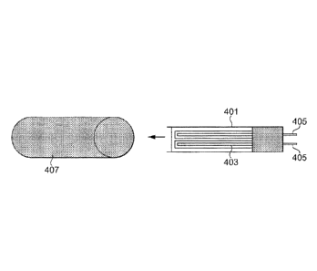
Figures 4 and 5a and 5b show two alternative embodiments of the heater of the
invention.
Figure 4 shows a first embodiment of the heater in use with an aerosol-forming
substrate. In
Figure 4, the heater 400 comprises a flat, rigid electrically insulating
substrate 401 having thereon
electrically conductive tracks 403. (The heater may be of the form shown in
Figure 1d(iii) or Figure
2e(iii).) The electrically conductive tracks are connectable to a power supply
(not shown) via
connections 405. The heater 400 may be inserted directly into a plug of
aerosol-forming substrate,
shown schematically at 407. The heater shown in Figure 4 may be used in either
the first or second
aspect of the invention. If the electrically conductive tracks have suitable
temperature coefficient of
resistance characteristics, they may act as resistive heaters as well as a
temperature sensor. The
heater may be combined with a thermally insulating material for thermally
insulating the at least one
heater from the outside of the electrically heated smoking system with which
it is used.
Figures 5a and 5b show a second embodiment of the heater. In Figures 5a and
5b, the
heater comprises an electrically insulating substrate 501. On a first portion
509 of the electrically
insulating substrate, there are electrically conductive tracks 503. The
electrically conductive tracks
503 are connectable to a power supply (not shown) via connections 505. On a
second portion 511
of the electrically insulating substrate 501, a thermally insulating
reflective honeycomb structure
CA 3046420 2019-06-13
14
507 is formed on the electrically insulating substrate. The heater of Figure
5a is designed to be
rolled into a tube from left to right, such that the portion 509 of the
electrically insulating substrate
having the electrically conductive tracks is on the inside and the portion 511
of the electrically
insulating substrate having the thermally insulating honeycomb structure 507
is on the outside.
Preferably the thermally insulating material is also highly reflective. The
resulting heater is shown
schematically in Figure 5b. The honeycomb structure may then be used to
thermally insulate the
heater and is preferably metal. The heater shown in Figure 5b may be used an
external heater, with
the thermally insulating reflective honeycomb structure 507 on the outside so
as to insulate the
heater from the outside of the electrically heated smoking system with which
it is used. This
reduces heat loss and also protects a user's hand from burning.
In Figures 5a and 5b, the thermally insulating reflective honeycomb structure
is shown as an
integral part of the heater. Alternatively, however, the honeycomb structure
may be formed
separately and used in the electrically heated smoking system as an
independent element. For an
external heater, the honeycomb structure may be wrapped around the
electrically insulating
substrate and electrically conductive tracks. For an internal heater, the
honeycomb structure may
be provided around the aerosol-forming substrate. In addition, alternative
structural arrangements
for the thermally insulating material are possible.
The heater shown in Figures 5a and 5b may also be used in the first aspect of
the invention:
if the electrically conductive tracks have suitable temperature coefficient of
resistance
characteristics, they may act as resistive heaters as well as a temperature
sensor.
As already mentioned, the manufacturing process illustrated in Figures 2a to
2e may also
be used to create the honeycomb structure 507. In a similar way to Figure 2d,
individual areas on
the electrically insulating substrate may be plated. If the underlying area is
then dissolved or
removed in another way, the plating will form air cavities providing thermal
insulation. In a preferred
arrangement, the air cavities are provided in a honeycomb structure, but other
arrangements are
also envisaged. In addition, the greatest thermal insulation is provided when
several layers of the
thermally insulating structure are used, for example, by rolling around or
stacking up several layers.
Advantageously, the plating may comprise only a single layer of gold. Gold is
particularly useful as
it will also reflect heat towards the inside of the electrically heated
smoking system, further reducing
heat loss. Alternatively, the plating may comprise a single layer of another
metal, such as silver.
Alternatively, the plating may comprise two layers, similar to that shown in
Figure 2d.
A number of advantages are provided by using a heater comprising electrically
conductive
tracks formed on an electrically insulating substrate. The size of components
required in the
electrically heated smoking system can be reduced. This allows the size of the
electrically heated
CA 3046420 2019-06-13
. =
smoking system to be reduced. In addition, the electrically insulating
substrate can be very thin
allowing further size reduction. In addition, some or all of the necessary
electronics, wiring and
connections may be incorporated on the same electrically insulating substrate
as the heater.
In addition, the heater may be manufactured more straightforwardly and cost
effectively
than some prior art heaters which require each heating element to be
individually formed. The
heater allows a great deal of flexibility in the design: the electrically
conductive tracks can be
straightforwardly arranged on the electrically insulating substrate as desired
and in order to give the
desired heat distribution.
In addition, assuming the material used for the electrically conductive tracks
has appropriate
temperature coefficient of resistance characteristics, the electrically
conductive tracks can act both
as resistive heaters and as a temperature sensor. This can further reduce the
size of the electrically
heated smoking system, since no separate temperature sensor will be required.
This will now be
described in more detail.
The temperature coefficient of resistance is a measure of the change in
resistance with a
given change in temperature. The general formula is given by:
R= R0(1+ aT)
where R is resistance, Ro is the resistance at a given temperature (usually 0
C), T is the
temperature, and a is the temperature coefficient of resistance. The
temperature dependence of
conductors is substantially linear.
In one method, the voltage across and the current through the electrically
conductive track
may be measured and the resistance determined. Then, assuming knowledge of Ro
and a (both of
which will be known for a given material), the temperature may be determined.
That is to say, the
electrically conductive track can act as temperature sensor as well as a
resistive heater.
The material must have a reasonably reliable temperature coefficient of
resistance, a. That
is to say, one that does not change considerably over time or under certain
conditions. In addition,
there may be advantages in using a material having a large value of the
temperature coefficient of
resistance, a, since this will mean that a relatively small change in
temperature results in a large
change in resistance. Materials having a large value of a include platinum,
nickel and copper.
CA 3046420 2019-06-13