Note: Descriptions are shown in the official language in which they were submitted.
85338070
SUCTION PIPE INLET DEVICE FOR CENTRIFUGAL PUMP
FIELD OF THE INVENTION
The present invention relates to a suction pipe inlet device for minimizing
entrance losses
in slurry systems involving centrifugal pumps used in the mining and other
processing
industries to transport mixtures of liquids and solids such as slurries.
BACKGROUND OF THE INVENTION
Mixtures of liquids and solids, such as slurries in mining and mineral
processing
operations, are typically transported using centrifugal pumps. Examples of
centrifugal
pumps may be appreciated from U.S. Patent Nos. 5,921,748, 7,074,017 and U.S.
Patent
Application Publication No. 2014/0037440.
Centrifugal pump performance can be negatively affected by a poor design of
the channel
that conducts the fluid, e.g. slurry, from the reservoir or sump to the
suction nozzle of the
pump, normally known as a suction pipe. Ideally the suction pipe should supply
to the
pump a steady flow of fluid with a uniform velocity profile while minimizing
frictional losses
in order to promote optimum pump performance, ensure throughput and system
reliability,
and maintain a reasonable energy consumption. Typical suction pipe designs
used for
handling slurry focus on safety and maintainability, usually incorporating
simple pipe
entrances at the sump, and as a consequence they tend to be inefficient due to
e.g. friction
losses at the suction inlet, high wear rates in the suction inlet due to non-
uniform velocity
and turbulence in the slurry, increasing the system head and therefore
reducing production
or increasing wear and energy consumption, this in addition to higher wear
rates in the
same suction pipe. For example, while typical "straight" pipe suction inlet
designs with
square corners protrude into the sump and can be pulled straight out of the
sump wall;
such a "straight" design causes unnecessarily high entrance losses that affect
negatively
the capacity and or performance of the pumping system. The "straight" design
also
causes the suction pipe inlet to wear out faster due to non-axial velocity
components and
turbulence in the slurry from what is known as the "vena contracta" effect. By
way of
further example, typical "bell mouth" pipe suction inlet designs (e.g. as
shown in US
2005/0229982) commonly used in water pump installations are difficult to use
in sumps
intended for slurry since the "bell mouth" design implies diameter dimensions
that exceed
the size of the suction pipe and therefore cannot be pulled out easily through
the wall of
1
Date Recue/Date Received 2022-11-25
CA 03046742 2019-06-11
WO 2018/109722
PCT/1B2017/057963
the sump, making it difficult to maintain or replace. Instead, when a "bell
mouth" design
requires maintenance or replacement, the retention tank is required to be
drained so that
the pipe inlet can be pulled out through the top of the retention tank
involving undesirable
and potentially unsafe operations.
OBJECT OF THE INVENTION
It is an object of the invention to overcome or at least alleviate one or more
of the above
problems and/or provide the consumer with a useful or commercial choice.
SUMMARY OF THE INVENTION
A suction pipe inlet device for a centrifugal pump is provided. The suction
pipe inlet device
may comprise a hollow tubular axisymmetric body along a longitudinal axis
having an open
first end adapted for fitting into or against a retention tank; an open second
end adapted
for fitting into or against an inflow end of a suction pipe having an outer
pipe diameter and
an inner pipe diameter; a converging section located closer to the retention
tank; a
diverging section located closer to the suction pipe; a throat located at the
intersection
point between the converging and diverging sections, the converging and
diverging
sections defining an interior converging-diverging geometry within the tubular
axisymmetric body and the throat defining a minimum inner cross sectional area
of the
tubular axisymmetric body.
In an exemplary embodiment, the open first end may comprise an inner cross
sectional
area located at or near the edge of open first end, wherein an area ratio
between the inner
cross sectional area of the open first end and the minimum inner cross
sectional area of
the tubular axisymmetric body is between approximately 0.36 and 0.81. In some
embodiments, the area ratio is between approximately 0.55 and 0.74.
In an exemplary embodiment, the converging section may be shaped as an arcuate
smooth contraction, e.g. it can be elliptical shaped, such that the elliptical
aspect ratio
between an ellipse major radius and ellipse minor radius is between 1- 6. In
some
embodiments, the aspect ratio (AR) may be between 2 - 4.
In an exemplary embodiment, the diverging section may be shaped such that an
included
angle of internal side walls increases from approximately 4 degrees in an area
closer to
2
85338070
the converging section to approximately 30 degrees in an area closer to the
suction pipe.
In some embodiments, the angle may increase from approximately 10 degrees in
the
area closer to the converging section to approximately 12 degrees in the area
closer to
the suction pipe.
In an exemplary embodiment, the suction pipe inlet device may be attached to
the inflow
end of a suction pipe by mechanical, adhesive or other forming means.
In an exemplary embodiment, the suction pipe inlet device may be a single
integral piece
with the suction pipe.
In an exemplary embodiment, the suction pipe inlet device may further comprise
a
plurality of spiral ribs or spiral grooves located on an interior portion of
the converging
section or diverging section for affecting fluid flow through the suction pipe
inlet device.
In an exemplary embodiment, the suction pipe may further comprise a liner with
a
predetermined thickness and wherein the suction pipe also has an inner pipe
lined wet
diameter. In some embodiments, the inner cross sectional area of converging
section
may reduce progressively to a minimum inner cross sectional area corresponding
to a
reduction in radii approximately 0.05 - 0.20 times the inner pipe lined wet
diameter. In
some embodiment, the reduction in radii may be approximately 0.07 - 0.13.
In an exemplary embodiment, the outer pipe diameter of the suction pipe may be
approximately equal to outer diameter of the hollow tubular axisymmetric body.
Other
details, objects, and advantages of the invention will become apparent as the
following
description of certain present exemplary embodiments thereof and certain
present
exemplary methods of practicing the same proceeds.
According to one aspect of the present invention, there is provided a suction
pipe inlet
device for minimizing entrance losses in slurry systems involving centrifugal
pumps; the
suction pipe inlet device being removably connected to a retention tank and
removably
connected to a suction pipe that is connected to a centrifugal pump downstream
of the
retention tank; a portion of the suction pipe inlet device protruding into the
retention tank;
the suction pipe inlet device comprising: a hollow tubular axisymmetric body
along a
longitudinal axis having an open first end in the retention tank; and an open
second end
downstream of the first end; a liner extending from the open second end and
having
3
Date Recue/Date Received 2022-11-25
85338070
an inner pipe lined wet diameter and a predetermined thickness: an outer pipe
diameter;
and an inner pipe diameter receiving the hollow tubular axisymmetric body and
the liner;
the hollow tubular axisymmetric body further comprising a converging section
located
closer to the first open end; a diverging section located closer to the second
open end; a
throat located at the intersection point between the converging and diverging
sections,
the converging and diverging sections defining an interior converging-
diverging geometry
within the tubular axisymmetric body and the throat defining a minimum inner
cross-
sectional area of the tubular axisymmetric body; and wherein the outer pipe
diameter is
selected and an outer surface of the suction pipe inlet device is shaped such
that the
suction pipe inlet device is configured to be extracted from the retention
tank and inserted
into the retention tank substantially free of interference, in a direction
along the
longitudinal axis, through a hole in the retention tank having a diameter that
is greater
than the outer pipe diameter.
According to another aspect of the present invention, there is provided a
method of
transporting slurry from a retention tank to a centrifugal pump downstream of
the retention
tank via a suction pipe connected to the centrifugal pump, the method
comprising:
providing a suction pipe inlet device for minimizing entrance losses in a
slurry system; the
suction pipe inlet device comprising: a hollow tubular axisymmetric body along
a
longitudinal axis having an open first end; and an open second end downstream
of the
first end; a liner in contact with the open second end and having an inner
pipe lined wet
diameter and a predetermined thickness; an outer pipe diameter; and an inner
pipe
diameter receiving the hollow tubular axisymmetric body and the liner; the
hollow tubular
axisymmetric body further comprising a converging section located closer to
the first open
end; a diverging section located closer to the second open end; a throat
located at the
intersection point between the converging and diverging sections, the
converging and
diverging sections defining an interior converging-diverging geometry within
the tubular
axisymmetric body and the throat defining a minimum inner cross sectional area
of the
tubular axisymmetric body; and, arranging the suction pipe inlet device such
that the open
first end is in the retention tank, the suction pipe inlet device is removably
connected to
the retention tank, the suction pipe inlet device is removably connected to
the suction
pipe, and a portion of the suction pipe inlet device protrudes into the
retention tank;
wherein the outer pipe diameter is selected and an outer surface of the
suction pipe inlet
device is shaped such that the suction pipe inlet device is configured to be
extracted from
3a
Date Recue/Date Received 2022-11-25
85338070
the retention tank and inserted into the retention tank substantially free of
interference, in
a direction along the longitudinal axis, through a hole in the retention tank
having a
diameter that is greater than the outer pipe diameter.
BRIEF DESCRIPTION OF THE FIGURES
Embodiments of the invention, by way of example only, will be described with
reference
to the accompanying drawings in which:
3b
Date Recue/Date Received 2022-11-25
CA 03046742 2019-06-11
WO 2018/109722
PCT/1B2017/057963
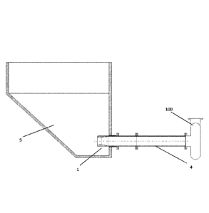
Figure 1 shows an overview of an exemplary embodiment of the suction pipe
inlet device,
a retention tank or sump, a suction pipe and a centrifugal pump.
Figure 2 shows a close-up view of an exemplary embodiment of the suction pipe
inlet
device.
Figure 3 shows a Computational Fluid Dynamics (CFD) result displaying velocity
of the
slurry within the suction pipe having the suction pipe inlet device of Figure
2 compared to
suction pipes having "straight" or "bell mouth" designs.
Figure 4 shows a Computational Fluid Dynamics (CFD) result displaying
turbulence of the
flow within the suction pipe having the suction pipe inlet device of Figure 2
compared to
suction pipes having "straight" or "bell mouth" designs.
Figure 5 shows computed entrance losses and calculated total dynamic head
losses within
the suction pipe having the suction pipe inlet device of Figure 2 compared to
suction pipes
having "straight" or "bell mouth" designs using Computational Fluid Dynamics
(CFD).
DETAILED DESCRIPTION OF THE INVENTION
Figure 1 shows an exemplary embodiment of the suction pipe inlet device 1, a
suction
pipe 4, a retention tank or sump 5 and a centrifugal pump 100. The suction
pipe 4
connects the sump 5 with the suction nozzle of the centrifugal pump 100, and
as shown
the suction pipe inlet device 1 protrudes into or against the retention tank
5. The suction
pipe inlet device 1 may be attached to or integral with the suction pipe 4,
e.g. it may be
attached by mechanical, adhesive or other forming means.
Referring now to Figure 2, the suction pipe inlet device 1 has a hollow
tubular axisyrnmetric
body along a longitudinal axis (L). Generally, the suction pipe inlet device 1
has an open
first end la and an open second end lb which is opposite the open first end
la. The open
first end la can protrude or project, at least partially, into the retention
tank 5 or can be
adapted such that the open first end la fits against an opening in the
retention tank 5. The
open second end lb can protrude or project, at least partially, into an inflow
end of a
suction pipe 4 or can be adapted such that the open second end lb fits against
the inflow
end of a suction pipe 4. The suction pipe 4 has an outer pipe diameter (0Dp)
and an
inside pipe diameter (IDp). The open first end la also has an inner cross
sectional area
4
CA 03046742 2019-06-11
WO 2018/109722
PCT/1B2017/057963
located at or near the edge or end of the open first end la. The suction pipe
4 may also
have a thickness T, with or without a liner 7, resulting in a flow area which
is defined herein
as the pipe lined wet inner diameter IDw.
As further shown in Figure 2, the suction pipe inlet device has an internal
profile and an
external profile. In an exemplary embodiment, the outer diameter or outer
surface of the
suction pipe inlet device 1 is approximately equal to the outer pipe diameter
of the suction
pipe 4. In an exemplary embodiment, the outer diameter or outer surface of the
suction
pipe inlet device 1 is shaped such that the suction pipe inlet device can be
extracted
through a generally circular hole or recess in the retention tank 5. In an
exemplary
embodiment the internal profile of the suction pipe inlet device 1 is designed
such that
there is an interior converging-diverging geometry within the tubular
axisymmetric body
and a throat lc within the tubular axisymmetric body which defines a minimum
inner cross
sectional area of the tubular axisymmetric body. The throat lc is located at
the intersection
point between a converging section 10 which is located closer to the retention
tank 5 and
a diverging section 20 which is located closer to the suction pipe 4.
In an exemplary embodiment of the converging section 10, the area ratio
between the
inner cross sectional area of the open first end la and the minimum inner
cross sectional
area at the throat lc of the tubular axisymmetric body is between
approximately 0.36 and
0.81, and preferably between approximately 0.55 and 0.74. In other words, the
internal
profile of the converging section 10 reduces progressively the cross sectional
area from
the open first end la to a minimum at the throat lc corresponding to a
reduction in radii
approximately by 0.05 to 0.20 times the pipe lined wet inner diameter IDw and
preferably
by approximately 0.07 - 0.13.
In an exemplary embodiment of the converging section 10, the open first end la
is shaped
to define an arcuate smooth contraction, as for example an elliptical shape
entrance, such
that an elliptical aspect ratio AR between an ellipse major radius R1 and an
ellipse minor
radius R2 is between 1 and 6 and preferably between 2 and 4. As shown in
Figure 2, the
ellipse major radius R1 is the length from the edge of the open first end la
and the throat
lc and the ellipse minor radius R2 is the radial height or thickness of the
converging
section 10.
5
CA 03046742 2019-06-11
WO 2018/109722
PCT/1B2017/057963
In an exemplary embodiment of the diverging section 20, the diverging section
20 is
shaped such that an included angle = of internal side walls 23 increases from
approximately 4 degrees in an area closer to the converging section 10 to
approximately
30 degrees in an area closer to the suction pipe 4 and preferably from
approximately 10
degrees in the area closer to the converging section 10 to approximately 12
degrees in
the area closer to the suction pipe 4. In other words, the internal profile of
the diverging
section 20 is shaped to increase progressively its cross sectional area (from
the throat lc
to the second open end lb towards the side closer to the suction pipe 4) as
for example
linearly with an angle = between the internal side walls 23 that can be within
4 to 30
degrees and preferably within 10 to 12 degrees.
In some embodiments, the suction pipe inlet device 1 can be manufactured with
a wear
resistant material or the suction pipe inlet device 1 may be protected with a
suitable wear
resistant liner such as a hard metal or an elastomer. In some embodiments, it
is envisaged
that a plurality of spiral grooves or spiral ribs may be disposed on a slurry-
side surface of
the converging 10 or diverging 20 sections in order to produce a swirling
motion in the
slurry that helps to control problems associated with settling of solids along
suction pipes
when feeding centrifugal pumps 100.
As shown in Figures 3 and 4, CFD analysis was conducted on the suction pipe
inlet device
1 contemplated here, on a typical "straight" design and on a typical "bell
mouth" design
indicating enhanced velocity patterns and less turbulence with the suction
pipe inlet device
1 compared with the traditional "straight" entrance design, offering a
solution that would
perform closer to the "bell mouth" design.
As shown in Figure 5, using the CFD results (as shown in Figure 3), inlet
entrance losses
were calculated for the suction pipe inlet device 1 contemplated here, for a
typical
"straight" design and for a typical "bell mouth" design at exemplary
conditions: slurry flow
= 13,200 gpm (3,000 m3/h); Pipe inner diameter = 18 inches (0.457 m). The
results
indicate a significant suction head loss of 3.33 ft (1.02 m) with the
conventional straight
pipe entrance design due mostly to entrance losses, which can be controlled as
shown in
this example with a bell mouth entrance predicted to reduce losses by 78% or
with the
suction pipe inlet device 1 disclosed here and predicted to reduce losses by
62%.
6
CA 03046742 2019-06-11
WO 2018/109722
PCT/1B2017/057963
There are numerous advantages to the suction pipe inlet device 1 described and
claimed
herein. For example, it is estimated that the suction pipe inlet device 1 will
(i) cut suction
inlet loss by 50-60% from the "straight" pipe design equating to a few feet in
overall total
dynamic head requirements; (ii) increase slurry flow as compared to the
"straight" design;
(iii) be longer lasting than the "straight" pipe design due to less
turbulence; (iv) be
interchangeable with the typical "straight" designs, meaning an increase in
pump
performance without changing the design of the sump and (v) be easier to
maintain and
replace than the "bell mouth" design due to the same diameter as the hole in
the retention
tank while at the same time being closer in function to the "bell mouth"
design.
It is to be understood that the form of this invention as shown is merely a
preferred
embodiment. Various changes may be made in the function and arrangement of
parts;
equivalent means may be substituted for those illustrated and described; and
certain
features may be used independently from others without departing from the
spirit and
scope of the invention as defined in the following claims.
LIST OF COMPONENTS
1 suction pipe inlet device
la open first end of suction pipe inlet device
lb open second end of suction pipe inlet device
1 c throat
4 suction pipe
5 retention tank / sump
7 liner
10 converging section
20 diverging section
23 internal side walls of diverging section
100 centrifugal pump
L longitudinal axis
ODp outer pipe diameter
IDp inner pipe diameter
IDw inner pipe lined wet diameter
R1 ellipse major radius
R2 ellipse minor radius
AR elliptical aspect ratio
7
CA 03046742 2019-06-11
WO 2018/109722
PCT/1B2017/057963
T predetermined liner thickness
. angle of internal side walls of diverging section
8