Note: Descriptions are shown in the official language in which they were submitted.
CA 03046804 2019-06-11
WO 2018/111708 PCMJS2017/065247
-1-
MEDICATION DELIVERY DEVICE WITH SENSING SYSTEM
BACKGROUND
[oom] The present disclosure pertains to medication delivery devices, and, in
particular,
to a sensing system in a medication delivery device.
[0002] A variety of medication delivery devices, including for example pen
injectors,
infusion pumps and syringes, are commonly used for periodic administration of
medications. It is important that the proper amount of medication be supplied
at these
times as the health of the patient is at stake. In many instances, failure to
accurately deliver
the appropriate amount of medication may have serious implications for the
patient.
[0003] The administration of a proper amount of medication requires that the
actual
dosing by the medication delivery device be accurate. The term "dosing" as
used herein
refers to two phases of administering a dose, namely, setting the dose amount
and
delivering the amount of the set dose.
[0004] Medication delivery devices often utilize mechanical systems in which
various
members rotate or translate relative to one another. In most instances, these
relative
movements between members are proportional to the dose amount set and/or
delivered
by operation of the device. Accordingly, the art has endeavored to provide
reliable systems
that accurately measure the relative movement of members of a medication
delivery device
in order to assess the dose set and/or delivered.
[0005] While useful, prior art sensing systems are not without their
shortcomings. For
instance, some sensing systems take up more space within a delivery device
than is
desirable, resulting in a delivery device that is more bulky or inconvenient
to use, or in a
delivery device that has to sacrifice one or more features to have room in a
compact device
for the sensing system. Some sensing systems use relatively expensive
componentry, or
may be overly complicated so as to adversely impact the cost of manufacture or
potentially
the system reliability.
[0006] Thus, it would be desirable to provide a medication delivery device
with a sensing
system that can overcome one or more of these and other shortcomings of the
prior art.
BRIEF SUMMARY
[0007] In one form thereof, the present disclosure provides a medication
delivery device
including a first member and a second member rotatable relative to the first
member about
CA 03046804 2019-06-11
WO 2018/111708 PCMJS2017/065247
-2-
an axis of rotation in proportion to at least one of an amount of a dose set
and an amount
of a dose delivered by operation of the medication delivery device. A radially
projected
wiper is coupled to the first member. An electrically operable sensing band is
coupled to
the second member. The sensing band is arranged in a curved shape and radially
disposed
relative to and in contacting relationship with the wiper, wherein, during
relative rotation
between the first and second members. The sensing band is operable to generate
outputs
associated with the relative angular position of the wiper along an
operational angular
length of the sensing band that is indicative of relative rotational positions
of the first and
second members. A controller electrically is coupled with the sensing band to
determine,
based on the outputs generated by the sensing band, at least one of the amount
of the dose
set and the amount of the dose delivered by operation of the medication
delivery device.
[ocoo8] In another form, a medication delivery device includes a first member
and a
second member rotatable relative to the first member about an axis of rotation
in
proportion to an amount of a dose set by operation of the medication delivery
device, and
a third member and a fourth member rotatable relative to the third member
about the axis
of rotation in proportion to an amount of a dose delivered by operation of the
medication
delivery device. A first wiper is coupled to the first member and projecting
in a radial
direction, and a second wiper is coupled to the third member and projecting in
a radial
direction. An electrically operable first sensing band is coupled to the
second member,
and an electrically operable second sensing band is coupled to the fourth
member. Each
of the first and second sensing bands is arranged in a curved shape and
radially disposed
relative to and in a contacting relationship with the first and second wipers,
respectively.
During relative rotation between the first and second members and relative
rotation
between the third and fourth members, each of the first and second sensing
bands is
operable to generate outputs associated with the relative angular position of
the
corresponding first and second wipers along an operational angular length of
the
respective first and second sensing bands that is indicative of relative
rotational positions
of the first and second members and the third and fourth members. A controller
is
electrically coupled with each of the first and second sensing bands to
determine, based on
the outputs generated by the first and second sensing bands, the amount of the
dose set
and the amount of the dose delivered by operation of the medication delivery
device.
[0009] In another form thereof, the present disclosure provides a medication
delivery
device for delivering medication from a cartridge having a barrel holding the
medication
between a movable plunger and an outlet. The device includes a main housing, a
cartridge
CA 03046804 2019-06-11
WO 2018/111708 PCMJS2017/065247
-3-
housing for holding the cartridge extending from the main housing, a drive
member, and
a dose delivery mechansism. The drive member includes a forward end for
engaging the
movable plunger, and has a length extending in an axial direction within the
main housing.
The dose delivery mechanism is for controlling advancement of the drive member
forward
within the main housing in the axial direction to move the movable plunger for
delivering
medication through the outlet. The dose delivery mechanism includes a first
member
rotatable relative to the main housing in proportion to one of an amount of a
dose set and
an amount of a dose delivered by operation of the medication delivery device.
The first
member is relatively rotatable to the main housing about an axis of rotation
extending in
the axial direction. A sensing system is provided and is operable to detect
relative
rotational positions of the first member and the main housing and generate
outputs
correlated to such relative rotational positions. The sensing system includes
a first wiper
and a first sensing band. The first wiper is coupled to the first member and
projecting in
a radial direction. The first sensing band is coupled to the main housing. The
first sensing
band is arranged in a curved shape around the axis of rotation and has a first
operational
angular length. The first sensing band is disposed in the radial direction
inward or
outward of the first wiper for a physical contact with the first wiper during
rotation of the
first member relative to the main housing. The first sensing band includes an
electrical
characteristic correlated with where along the first operational angular
length the first
sensing band is operationally engaged in the radial direction due to the
physical contact
with the first wiper. A controller is in electrical communication with the
sensing system
to determine, based on outputs of the sensing system, at least one of the
amount of the
dose set and the amount of the dose delivered by operation of the medication
delivery
device.
BRIEF DESCRIPTION OF THE DRAWINGS
[0010] The above-mentioned and other advantages and objects of this invention,
and the
manner of attaining them, will become more apparent, and the invention itself
will be
better understood, by reference to the following description of embodiments of
the
invention taken in conjunction with the accompanying drawings, wherein:
[oon] Fig. 1 is a perspective view of a medication delivery device in the form
of an
injection pen without a cap and prior to a mounting of a needle assembly;
[0012] Fig. 2 is a side view in partial cross-section of the injection pen of
Fig. 1 with a
needle assembly attached and after a dose for delivery has been set;
CA 03046804 2019-06-11
WO 2018/111708 PCMJS2017/065247
-4-
[0013] Fig. 3 is an abstract cross-sectional view taken along line 3-3 of Fig.
2 further
showing a sensing system;
[0014] Fig.4 is a partial, abstract cross-sectional side view of the injection
pen of Fig. 1;
[0015] Fig. 5 is a perspective view of Fig. 3;
[0016] Fig. 6 is an exploded perspective view of the sensing band of the
sensing system
in an uncurved, or straight, configuration;
[0017] Fig. 7 is a perspective view of the sensing band of Fig. 6 in a ring-
shaped
configuration;
[0018] Fig. 8 is a schematic of an electrical circuiting of the sensing system
with the
controller microprocessor;
[0019] Fig. 9 is an abstract perspective view of another configuration of
sensing bands of
a sensing system;
[0020] Fig. lo is a partial, abstract cross-sectional view similar to Fig. 4
of the sensing
system bands of Fig. 9 and a suitable wiper installed in the device of Fig. 1;
[0021] Fig. 11 is a perspective view of an alternate embodiment of a
medication delivery
device with sensing system;
[0022] Fig. 12 is a partial perspective view of the device of Fig. n showing
the dose
delivery detection module detached from the remainder of the device; and
[0023] Fig. 13 is a cross-sectional view, taken along line 13-13 in Fig. 11,
of the dose
delivery detection module, with a portion of the remainder of the device shown
not in
cross-section.
[0024] Fig. 14 is a partial perspective view, and with a region removed to
reveal the
interior, of an alternate embodiment of a medication delivery device with
sensing system;
[0025] Fig. 15 is a partial perspective view of select portions of the device
with sensing
system of Fig. 14;
[0026] Fig. 16 is a longitudinal cross-sectional view taken along line 16-16
of Fig. 15;
[0027] Fig. 17 is a perspective view similar to Fig. 15 showing only the
sensing bands and
the core member;
[0028] Fig. 18 is an exploded perspective view of the components shown in Fig.
17;
[0029] Fig. 19 is a partial, exploded perspective view of a wiper component
and drive
sleeve of the medication delivery device with sensing system of Fig. 14;
[0030] Fig. 20 is a partial, opposite perspective view of the wiper component
and drive
sleeve of Fig. 19;
CA 03046804 2019-06-11
WO 2018/111708 PCMJS2017/065247
-5-
[0031] Fig. 21 is a partial and exploded perspective view of a wiper component
and barrel
of the medication delivery device with sensing system of Fig. 14;
[0032] Fig. 22 is a partial perspective view of the wiper component and barrel
of Fig. 21;
[0033] Fig. 23 is a perspective view, in partially exploded form, of portions
of an alternate
embodiment of a medication delivery device with sensing system;
[0034] Fig. 24 is a partial perspective view, partially in longitudinal cross-
section, of the
device portions of Fig. 23 within a housing piece; and
[0035] Fig. 25 is an abstract view of a sensing band of the sensing system
from Fig. 23 in
an uncurved, or straight, configuration.
[0036] Corresponding reference characters indicate corresponding parts
throughout the
several views. Although the drawings represent embodiments of the present
invention,
the drawings are not necessarily to scale, and certain features may be
exaggerated or
omitted in some of the drawings in order to better illustrate and explain the
present
invention.
DETAILED DESCRIPTION
[0037] Referring now to Figs. 1-2, there is shown a medication delivery device
equipped
with a sensing system that is described further as being used to determine the
amount of
a dose set by operation of the device. Such amount is determined based on the
sensing of
relative rotational movements during dose setting between members of the
medication
delivery device, where the sensed movements are correlated as applicable to
the amount
of the dose set. In different embodiments, the sensing system is configured to
determine
the amount of at least one of the dose set and the dose delivered by operation
of the device,
or alternatively both the amount of the dose set and the amount of the dose
delivered by
operation of the device. One of the advantages of the disclosed embodiments is
that a
medication delivery device with sensing system may be provided that can
accurately and
reliably assess the amount of medication that has been set and/or delivered by
that device.
Another of the advantages is that a medication delivery device with sensing
system may be
provided that requires a limited number of individual parts. Still another of
the advantages
is that a medication delivery device with sensing system may be provided which
has a
compact form factor.
[00381 The shown device is a reusable pen-shaped medication injection device,
generally
designated wo, which is manually handled by a user to selectively set a dose
and then to
inject that set dose. The description of device 100 is merely illustrative as
the sensing
-6-
system can be adapted for use in variously configured medication delivery
devices,
including differently constructed pen-shaped medication injection devices,
differently
shaped injection devices, and infusion devices. The medication may be any of a
type that
may be delivered by such a medication delivery device. Device 100 is intended
to be
illustrative and not limiting as the sensing system described further below
may be used in
other differently configured devices. Device roo is similar in many respects
to a device
described in U.S. Patent No. 7,195,616.
[0039] As used herein, the term "coupled" encompasses any manner by which a
first item
is caused to move in unison with or in proportion to a second item as the
second item
moves. Items are rotationally coupled if they are caused to rotate together.
Coupling
systems may include, for example, connections provided through splines, gears
or
frictional engagement between the members, or similar connections provided by
other
components which indirectly couple the members. Where applicable, an item may
be
coupled to another item by being directly positioned on, received within,
attached to, or
integral with the other item, or otherwise secured thereto, directly or
indirectly.
[0040] The term "fixed" is used to denote that the indicated movement either
can or
cannot occur. For example, a first member is "rotatably fixed with" or "fixed
against
rotation relative to" a second member if the first member is not able to
rotate relative to
the second member.
[0041] Medication injection device 100 includes an outer housing that supports
the
internal components of the device. The housing is shown as having a rear or
main housing
102 and a forward or cartridge housing 104. Main housing 102 is configured to
hold a drive
assembly of the device, which assembly is a strictly user powered, mechanical
assembly as
described but may in alternate embodiments be a motorized assembly. Cartridge
housing
104, also known as the cartridge retainer, holds a cartridge io6 filled with
medication to
be delivered by device operation. Cartridge retainer 104 is detachably
connectable or
mountable to main housing 102 via external threading 110 on a protruding
collar portion
112 of main housing 102 which mates with internal threading 114 on a ring
portion 116 at
the proximal end of cartridge retainer 104. Suitable detachable connecting
elements other
than threadings 110 and 114 are known in the art and naturally may be
employed, such as
a bayonet fitting, or the use of an additional latching component.
[0042] Cartridge retainer 104 includes an internal hollow 105 suited to
removably receive
cartridge 106, thereby allowing a cartridge to be inserted therein, and then
removed
Date Recue/Date Received 2020-12-04
CA 03046804 2019-06-11
WO 2018/111708 PCMJS2017/065247
-7-
therefrom when depleted and replaced with a fresh cartridge of similar design.
Openings
118 in cartridge retainer 104 allow visibility of the cartridge contents. A
detent feature 120
provided on the exterior of cartridge retainer 104 allows for a not shown
protective cap to
be detachably mounted over the cartridge retainer 104 when a needle assembly
125 is not
attached to the cartridge retainer 104. Although cartridge retainer 104 is
described herein
as being a reusable component, the cartridge retainer 104 can be integrated
with, and
therefore be disposable with, the cartridge 1o6.
[0043] Medication cartridge 106 is of conventional design, including a barrel
130 having
an interior reservoir filled with medication which is sealed at one end by a
slidable plunger
or piston 132 and sealed at the other end by a septum 134 held by a crimp ring
136.
[0044] A needle assembly 125 detachably mountable to an externally threaded
distal end
122 of cartridge retainer 104 pierces the septum 134 when so mounted. The
pierced
septum through which the needle extends serves as an outlet during dispensing
for the
medication within the reservoir of barrel 130, which medication is delivered
through the
needle assembly 125 by operation of device too. The cartridge 1o6 can hold
multiple doses
of medication, or even a single dose, depending on the purpose of device 100.
[0045] Medication injection device too is shown in Fig. 1 in its "zero
position" at which
the device has not been set for delivery of any dose. This zero position
setting is indicated
by the number "o" visible somewhere on the device, such as, for example, on an
electronic
dose display 140 in Fig. 1. In Fig. 2, device 100 is arranged after being
manipulated to set
a dose of thirty units for delivery, and the number "30" would be visible,
such as, for
example, on the display 140.
[0046] Medication injection device loo is typical of many such reusable
devices including
a manually-powered dose delivery mechanism, generally designated 150, that
controls
forward or distal advancement of a drive member, generally designated 16o.
Drive
member 16o advances within the cartridge barrel 130 to directly engage and
advance
plunger 132. As shown in Fig. 2, dose delivery mechanism 150 includes a dose
knob 152
connected via a tube 154 to a mechanical drive assembly abstractly indicated
at 156 that is
housed within main housing 102. When knob 152 is turned by a user to set a
dose for
injection, dose knob 152 and tube 154 screw out together proximally from main
housing
102. When a user applies a plunging distal force on the proximal end 158 of
dose knob 152,
the resulting purely translational axial motion of dose knob 152 and tube 154
distally
forward into main housing 102 is converted by drive assembly 156 into a
smaller motion
CA 03046804 2019-06-11
WO 2018/111708 PCMJS2017/065247
-8-
of drive member 160 forward from main housing 102 into the interior of
cartridge barrel
130.
[0047] Drive member 16o is formed in two pieces including a forward end 163
that
directly engages the cartridge plunger 132, and a shaft 165 that axially
extends rearward
from forward end 163 into main housing 102. The shaft 165 is threaded and is
engaged
with drive assembly 156 to be screwed out from main housing 102 and thereby
driven
forward. Shaft 165 is shown threadedly engaged with a housing bulkhead 168,
which
housing bulkhead is shown integral with main housing 102 but can be separately
formed
and fixedly attached thereto. Forward end 163 is provided in the form of an
enlarged foot
that is mounted on shaft 165 to allow relative rotation, allowing foot 163 to
engage plunger
132 without relative rotation therebetween as shaft 165 screws out. While this
foot and
shaft two-piece construction of drive member 16o is preferred when shaft 165
screws out
from the housing during advancement, such a construction is not required in
devices,
particularly if the drive member simply translates as it is forced forward
from the housing,
in which case a single piece drive member construction may be more acceptable.
[0048] Device roo uses an electronic dose display 140 rather than a helically
marked dial
display as used in many other reusable injection devices. Display 140 is
circuited to and
controlled by an electronic controller or computing assembly 170 mounted
within main
housing 102. Controller 170 can include conventional components such as a
processor,
power supply, memory, etc.. Controller 170 is programmed to achieve the
electronic
features of device roo, including causing the display of set doses. The set
dose displayed
in display 14.0 is determined by the interaction of dose delivery mechanism
150 with a
sensing system, abstractly shown at 175, which is electrically circuited with
controller 170.
[0049] With additional reference to Figs. 3-5, sensing system 175 is coupled
to two
members of device roo which, when a dose is set by a user screwing dose knob
152 out
from housing 102, are relatively rotatable in proportion to the amount of such
set dose.
Depending on the configuration of device roo and in particular the drive
assembly 156,
those two members of device roo to which sensing system 175 is coupled also
can be
rotatable relative to each in proportion to the amount of a dose delivered by
plunging
operation of dose knob 152, and in which case sensing system 175 can
additionally be used
in determining the delivered dose. Alternatively, in another embodiment where
dose
delivered instead of dose set is sensed, sensing system 175 is positioned for
sensing dose
delivered by being coupled to two members of device 100 which, during dose
delivery, are
CA 03046804 2019-06-11
WO 2018/111708 PCMJS2017/065247
-9-
relatively rotatable in proportion to the amount of dose delivered, but which
two members
do not relatively rotate during dose setting.
[00501 Sensing system 175 operates to detect relative rotational positions of
the first and
second device members to which it is coupled and generates outputs correlated
to such
relative rotational positions. Sensing system 175 includes a sensing band i8o
and a wiper
185. In device loo, sensing band 180 is coupled to housing 102, and wiper 185
is coupled
to a part of drive assembly 156 that at select times of device use rotates
within the housing
interior. Sensing band 180 alternatively can be coupled to housing 102 via one
or more
intermediate components, and further alternatively can be coupled to housing
102, either
directly or directly, to not rotate relative to the housing but be free to
move axially, such as
if the wiper 185 with which it engages moves axially during device use and
sensing band
18o were attached directly to a component rotatably, fixedly, and axially
movably, mounted
to the housing 102.
[0051] As abstractly shown in Fig. 3, sensing band i8o is directly attached,
such as with
an adhesive, to the interior circumferential and radially inwardly facing
surface 188 of
housing 102, while wiper 185 is directly attached, such as with an adhesive or
by being
integrally formed therewith, to an outer radial surface 190 of a part of the
drive assembly
156. Drive assembly 156 can take various forms, but typically involves
multiple interacting
parts, and wiper 185 is shown positioned on a rotatable part of this assembly
so as to have
direct contacting access to the sensing band 180.
[0052] Wiper 185 includes a body 196 that projects radially outward from its
inward end
194 to its outward end 198. Outward end 198 has a rounded apex that provides a
precise
point of contact for sliding engagement with sensing band 18o along the
circumferential
extent of the band. Wiper body 196 has an axially extending length parallel to
the axis of
rotation, indicated at 200, about which rotates the part of the drive assembly
156 from
which the wiper projects. As no electrical current is routed through it, wiper
185 can be
formed entirely of an electrically non-conductive material such as a
thermoplastic
elastomer such as silicone.
[0053] The wiper alternatively can be a single point contact, without the
axial length as
shown. The wiper need not extend the width, as extending in the axial
direction, of the
resistor strip within sensing band 180. Providing wiper 185 with an axial
length can
account for both tolerances within the design of the device as well as axial
motion within
the device of the wiper 185 relative to the sensing band 18o and housing 102.
CA 03046804 2019-06-11
WO 2018/111708 PCMJS2017/065247
-10-
[0054] The radial height of wiper body 185 is designed to span the annular
space or gap
202 within the housing interior between sensing band 18 o and drive assembly
156. Wiper
185 projects sufficiently far radially outward to provide at least a minimum
application
force and thereby operationally engage sensing band 180 as described further
below. Such
force can be controlled by the manufacturer through the material selection and
processing,
such as tempering, as well as the geometry of the wiper and its residual
compression within
156. To better ensure a proper engagement with sensing band 18o at all angular
positions
of the drive assembly 156, and thereby wiper 185, relative to housing 102,
wiper 185 can be
biased radially outward from drive assembly 156. Such a biasing can be
provided by a
material resiliency resulting from forming wiper 185 out of a durable but
elastic material
such as a thermoplastic elastomer or butyl rubber with a suitable durometer.
The biasing
can also or alternatively be provided by an additional spring element acting
in a radial
direction between wiper 185 and drive assembly 156. Still further, a biasing
of the sensing
bands radially inwardly, such as by placing spring elements to act radially
between the
outer radial periphery of the sensing bands and the housing radial interior
surface, can be
done alternatively or additionally.
[0055] Wiper 185 and sensing band 180 are in radial alignment when active to
sense
relative rotational positions. In device embodiments where for example the
drive assembly
156 moves axially from one state, where the sensing system 175 is not used, to
a second
state, at which the sensing system 175 is used, the wiper 185 and sensing band
180 can be
axially spaced when not being used.
[0056] Other wiper shapes than the one shown in Fig. 3 can be used to activate
sensing
band 180. Such additional wiper shapes include round protrusions, or journaled
disks or
cylinders that result in rolling contact with sensing band 180.
[0057] Sensing band 180 is configured to generate an electrical output based
on where
along its angularly extending operational length it is directly contacted by
wiper 185.
Sensing band 180 is arranged within housing 102 in a curved shape around axis
of rotation
200, and the band is disposed radially outward of wiper 185. Sensing band 18o
is shown
in Fig. 3 as being annular in shape to extend the full 360 degrees of the
housing internal
circumference and completely ring the axis of rotation 200. Alternatively,
sensing band
180 can be in a ring shape that does not completely encircle or ring the axis
of rotation.
[0058] Sensing band 180 can be formed by a membrane potentiometer manufactured
in
the curved shape to facilitate assembly within device loo to remove residual
stresses. One
suitable sensing band is available from Tekscan Incorporated. The membrane
CA 03046804 2019-06-11
WO 2018/111708 PCMJS2017/065247
-11-
potentiometer is an assembly of components that are abstractly shown in an
uncurved
state in Fig. 6, but descriptions of radial and angular refer to the sensing
band in the
rounded configuration shown in the other figures. The sensing band 180
includes first and
second substrates or backing strips 205, 207, and first and second electrical
strips 209 and
211 that sandwich a spacer 213. Substrates 205 and 207, and spacer 213, are
made of a
pliable plastic that is electrically non-conductive such as PET (polyethylene
terephthalate)
or a polymide film such as Kapton. Alternatively, spacer 213 can be a printed
material
deposited directly onto either substrate 205 or 207 by means such as screen
printing.
Spacer 213, which serves to keep the electrical strips 209 and 211 apart
absent a sufficient
force applied by the wiper, can also have an adhesive property to connect the
substrates
205 and 207 together. Substrates 205 and 207 and the outer edges of spacer 213
form the
exterior of sensing band 180, and, when sealed together along their peripheral
regions,
protectively encase strips 209 and 211. Strips 209 and 211 are secured to the
substrates
205 and 207 and/or the spacer 213, or can be otherwise formed such as screen
printed, for
example, directly to the substrates.
[0059] Electrical strips 209 and 211 when in a neutral state are held within
sensing band
180 in spaced relationship due to the interposition of spacer 213. When band
180 is in its
curved configuration within device 100, strip 209 is disposed radially inward
of strip 211,
and absent an external force the strips 209 and 211 are radially spaced
resulting in no
electrical connection therebetween. In this radially spaced relationship,
strips 209 and 211
are directly facing each other through the central slot-shaped opening 214
within spacer
213. Not shown dielectric projections also can be provided on one of the
electrical strips
209 or 211 within opening 214 to ensure the strips 209 and 211 remain so
radially spaced
absent a wiper induced movement. Such projections can be provided, such as by
screen
or jet printing, in any suitable pattern that maintains the strip radial
spacing, such as
discrete bumps arranged in a polka dot pattern, parallel ribs oriented axially
that span the
strip width and which are spaced from each other along the length of the
strip, parallel ribs
oriented at an angle relative to the strip width which span that strip width
and which are
spaced from each other along the length of the strip, or parallel ribs
oriented
circumferentially that span the strip length and which are spaced from each
other along
the width of the strip.
[0060] Electrical strip 211 is an electrical resistor element that has an
electrical resistance
that varies linearly along its length that extends from a first angular end
218 to a second
angular end 220. A first electrical lead 222 is circuited with and extends
from end 218,
CA 03046804 2019-06-11
WO 2018/111708 PCMJS2017/065247
-12-
and a second electrical lead 224 is circuited with and extends from end 220.
Lead 224 is
routed at 226 near the electrical strip side to a lead end 228 parallel to
lead 222 which
facilitates the electrical connection of sensing band 180 with the device
circuitry.
[0061] Electrical strip 209 is an electrical conductor element with very low
electrical
resistance, such as made of silver, copper or gold, having a length that
extends from a first
angular end 230 to a second angular end 232. A first electrical lead 235 is
circuited with
and extends from end 230.
[0062] While leads 235, 222 and 228 are shown as positioned in an extension of
the
substrates 205 and 207 that extends in the angular direction along the lengths
of such
substrates, in an alternate embodiment such leads can be routed to an
alternate substrate
portion that alternatively or additionally extends laterally, or in the axial
direction, from
the substrates to facilitate an electrical connection.
[0063] Strip 209 is sufficiently flexible along its length to allow its
deflection in the
outward radial direction, at the point where it is acted upon, through the
substrate 205, by
wiper 185, to be in direct physical and electrical contact with electrical
strip 211. This wiper
causes a compression, indicated at 219 in Fig. 3, that deflects strip 209
radially outward
thereat to result in wiper 185 operationally engaging the sensing band 180 by
causing an
electrical contact between strips 209 and 211 thereat, but with the strips
otherwise
remaining radially spaced. The resistance between electrical leads 235 and 222
varies
linearly with the distance between the angular end 218 and the point of
contact between
strips 209 and 211. The resistance between electrical leads 235 and 228 varies
linearly
with the distance between the second angular end 220 and the point of contact
between
strips 209 and 211. The resistance between the electrical leads 222 and 228 is
equal to the
sum of the electrical resistance between leads 235 and 222 plus the resistance
between
leads 235 and 228.
[0064] In an alternate embodiment, and provided resistor element 211 has
flexibility
properties similar to that of conductor element 209 to allow a deflection by
wiper
engagement, sensing band 180 can be configured to have resistor element 211 be
radially
inward of conductor element 209 in the shown device 100.
[0065] Sensing band 180 is shown in Fig. 7 removed from the remainder of
device 100.
Sensing band 180 is exactly circumferentially wrapped around the axis of
rotation 200 so
as to minimize the use of axial space within device 100 devoted to sensing
system 175.
Band 180 can alternatively have its ends axially offset so that band 180 is
arranged as a
helix. Sensing band 180 is operational to sense wiper 185 at any point along
the angular
CA 03046804 2019-06-11
WO 2018/111708 PCMJS2017/065247
-13-
length of sensing band 180 at which electrical strips 209 and 211 are present
and capable
of being brought into electrical contact by a radial deflection caused by
wiper 185. Sensing
band 180 has an electrical characteristic correlated with where along its
angular
operational length it is operationally engaged due to the physical contact
with wiper 185.
[0066] For the shown embodiment, the angular operational length of sensing
band 18o
for which sensing is effective is less than 360 degrees around the axis of
rotation 200 for
the wrapping of the band 180. This length is due to end region 236 of spacer
213 proximate
the first end 237 of band 180, at which region there is no sensing. This
spacer end region
236 is overlapped by the opposite second end 238 of band 18o, with sensing
band 18o
being sized such that effective portions of electrical strips 209 and 211
proximate the
opposite end region 239 of spacer 213, while not angularly overlapping spacer
end region
236, stop immediately before such an overlapping as shown in Fig. 7. As a
result, the
operational angular length extends less than 360 degrees around the housing
inner
circumference, and in particular 360 degrees minus the portion of the inner
circumference
spanned by the spacer end region 236. One suitable operational length extends
at least
345 degrees. In an alternate embodiment in which a sensing band i8o is longer,
the
effective length of the electrical strips 209 and 211 can overlap end region
236.
[0067] Controller 170 includes a microprocessor 240 electrically circuited
with sensing
band 18o as shown schematically in Fig. 8. The electrical outputs from the
sensing band
180 that reach microprocessor 240 are processed by the microprocessor to
identify the
amount of the dose set by operation of the device loo, specifically based on
the
microprocessor 240 determining relevant movement of the drive assembly 156
relative to
the main housing 102 during dose setting.
[0068] As represented in Fig, 8, an electrical power source 250, such as a 1.8
volt source,
that is housed within device loo within controller 270 is circuited at node
242 with lead
222 from resistor element 211 which acts as an input to sensing band 180. The
output lead
end 235 of conductor element 209 is circuited at node 256 to an input port 258
of the
electrically grounded microprocessor 240 through a signal amplifier 260. Node
256 is
grounded through a voltage divider resistor 262 to provide a voltage to the
microprocessor
240 that is proportional to the resistance between nodes 256 and 242. The
output lead
228 of resistor element 211 is circuited at node 244 to a second input port
246 of the
electrically grounded microprocessor 240 through signal amplifier 250, and
node 244 is
grounded through a voltage divider resistor 252 to provide a voltage to the
microprocessor
240 that is proportional to the resistance between nodes 244 and 242.
CA 03046804 2019-06-11
WO 2018/111708 PCMJS2017/065247
-14-
[0069] Due to the voltage signal received by microprocessor 240 via node 256
being
dependent on where along the angular length of resistor element 211 the wiper
185 has
caused resistor element 211 to be contacted by the deflection of conductor
element 209,
controller 170 can determine the relative positions of the members sensed by
sensing
system 175, namely the drive assembly 156 and the housing 102.
[0070] The shown circuitry results in a differential voltage signal being
provided at
inputs 246 and 258 to the microprocessor 240 that can be used to compensate
for any
variations in the output of sensing band 180 that can occur over time or due
to
environmental conditions. Such a circuitry differential signal can not be
required with a
sensing band in an alternate embodiment.
[0071] The operational angular length of sensing band 180 being less than
three hundred
sixty degrees results in a sensing gap around the housing inner circumference.
Unless the
wiper has an angular length larger than the sensing gap, there is time during
the
circumferential travel of the wiper that the presence of wiper 185 cannot be
actually sensed
by the sensing system 175. The controller 170 can be programmed to understand
that
sensing system 175 not outputting a wiper engagement in fact corresponds to
wiper 185
being aligned with the sensing gap. If such a programming is not desired, or
if the sensing
gap is larger than the angular resolution needed for a particular application,
an alternate
sensing system can be employed.
[0072] One such alternate sensing system is abstractly shown in pertinent part
in Figs. 9
and 10. The sensing system, generally designated 175', can be used in place of
sensing
system 175 in device loo to sense the relative positions of housing 102 and
drive assembly
156. Sensing system 175' includes first and second sensing bands i8oa and i8ob
each the
same structurally as sensing band 180 with electrical circuiting to the device
controller but
not each other. Sensing bands i80a and i8ob are coaxially arranged and each is
in an
exact circumferential arrangement around axis of rotation 200. Sensing bands
i80a and
i8ob are closely spaced axially with the electrical strips of each band 18oa
and i8ob not
being in an axially overlapping relationship with the electrical strips of the
other.
[0073] Sensing band i80a includes a resistor element 211a and a conductor
element
209a, while sensing band i8ob includes a resistor element 211b and a conductor
element
209b. The angular operative length of each of band 180a and i8ob is shown in
Fig. 9 as
being the same as band 180, and each of such lengths extends only partially
around a
circumference of the drive assembly 156. Such a configuration results in
sensing band
i8oa having a sensing circumferential gap 181a and sensing band i8ob having a
sensing
CA 03046804 2019-06-11
WO 2018/111708 PCMJS2017/065247
-15-
circumferential gap 1.81.b. While the operative lengths of bands 180a and
18013 are shown
as being equal, such is not required so long as one sensing band covers the
sensing
circumferential gap of the other.
[0074] The wiper of sensing system 175' is shown as a single, axially
extending element
185' that engages both sensing bands 180a and i8ob. Different axial regions of
wiper 185'
engage different sensing bands i80a and i8ob. In a not shown alternate
embodiment, the
wiper need not be a single continuous member as shown in Fig. lo but instead
can be two
distinct wipers, or can have an interruption along its axial length which does
not interfere
with the operation of engaging the sensing bands i8oa and i8ob as appropriate.
[0075] Sensing bands i80a and i8ob are angularly staggered as shown in Fig. 9
such that
sensing circumferential gaps 181a and ithb do not line up at all axially. As a
result, when
wiper 185' is oriented so as to be located within angular gap 181a it will
simultaneously and
necessarily be engaging sensing band i8ob and not be positioned so as to try
to
operationally engage within gap 181b. Controller 170 is programmed to
understand from
the combination of outputs from sensing bands 1.80a and i8ob where the wiper
185', and
therefore the drive assembly 156, is located relative to the housing 102. The
controller 170
can also use the combination of outputs to determine if one of the sensing
bands is not
operating correctly.
[0076] Sensing bands i8oa and i8ob are shown in Figs. 9 and m as being
separately
formed and positioned within a device. In an alternate construction, the
resistor elements,
conductor elements and leads of the shown two sensing bands can all be
provided on
appropriately sized and shaped, common substrates, and with an appropriate
common
spacer. This construction results in a single sensing band, with two sets of
angularly
staggered resistor and conductor elements, each set with their own electrical
contacts for
circuiting to the device controller but not the other set, which can be
handled as a single
unit.
[0077] In a still further alternate embodiment which is not shown, the sensing
circumferential gaps of the two, or even more, sensing bands can be axially
aligned.
However, the wiper element would have portions on different axial segments of
the drive
assembly 156, which wiper portions would be appropriately angularly spaced
around the
drive assembly 156 so as to not all simultaneously engage the sensing gaps of
the multiple
sensing bands.
[0078] Referring now to Fig. 11, there is shown in perspective view an
alternate
medication delivery device with sensing system. The sensing system is
incorporated into
CA 03046804 2019-06-11
WO 2018/111708 PCMJS2017/065247
-16-
a dose delivery detection module, generally designated 400, that is detachably
mounted
over the proximal end of the remaining portion of the delivery device,
generally designated
405. When module 400 is mounted as shown, its sensing system abstractly
represented
at 410 in Fig. ii detects relative rotational positions of module housing
parts, and thereby
relative rotational positions of first and second members of device portion
405, during
dose delivery and generates outputs correlated to such relative rotational
positions which
are used by controller 415 to identify the dose delivered by operation of the
device.
[0079] Fig. 12 shows module 400 either prior to its releasable mounting to
device portion
405, or after having been demounted from device portion 405.
[0080] With additional reference to Fig. 13, sensing system 410 includes a
wiper 420 and
a sensing band 425. Wiper 420 is coupled to and projects radially inwardly
from an
interior circumferential surface 432 of a module housing part 450. Sensing
band 425 is
coupled to and rings the radially outer periphery or surface 434 of module
housing part
455. Sensing band 425 is shown in Fig. 13 as being axially offset slightly
above the axial
center of wiper 420 due to housing part 455 shifting axially downward relative
to housing
part 450 during dose delivery in an amount equal to the axial offset shown in
Fig. 13, which
figure represents the device as configured before a dose setting. During dose
delivery the
sensing band 425 and wiper 420 are completely radially aligned. Sensing band
425 is
electrically connected with not shown wiring to controller 430 secured within
an interior
hollow 457 of housing part 455. Other than as described herein and the
reversal of the
radial positions of the components, and that such components are used for
sensing a dose
delivered instead of a set dose as further described below, wiper 420, sensing
band 425
and controller 430 are structured and function similarly to the corresponding
wiper 185,
sensing band 180 and controller ro of device 100.
[0081] Module housing part 450 includes a connection 460 complementarily
shaped to
a skirt 500 of the dose dial assembly 502 for a removable mounting of module
400 to the
remaining portion of the delivery device 405. Skirt 500 is shown separately
formed from
but is fixedly secured, both rotatably and axially, with the dose dial
assembly 502, and the
connection 460 results in housing part 450 being rotatably and axially fixed
with the dial
assembly 502. Module housing part 455 includes a base face 465 that engages a
top surface
504 of a button 506 to be rotatably fixed therewith.
[0082] For the device of Figs. 11-13 to be set for delivery, module 400 is
rotated relative
to pen housing 5 o8, which screws dial assembly 502 and button 5o6 upward and
together
relative to the pen housing 508. A splined connection indicated at 464 between
housing
-1 parts 45 45o and 455 aids in keeping these housing parts rotating together
during dose
setting.
[0083] For the device of Figs. 11-13 to deliver a set dose, by the user
applying a plunging
force on the top surface 470 of housing part 455, housing part 455, as well as
button 506,
are moved downward without rotation relative to housing part 450 and the dial
assembly
502. This motion disconnects the splined connection 464 as well as a not shown
clutch
connection between button 506 and dial assembly 502, and causes an alignment
of sensing
band 425 with wiper 420. Further plunging moves housing part 455 and button
506
axially downward without rotation while simultaneously screwing the housing
part 450
and the dial assembly 502 back into pen housing 508. The relative rotation of
housing
parts 450 and 455 is sensed by the operative interaction of wiper 420 with
sensing band
425, which allows the controller 430 to determine the dose delivered.
[0084] Device portion 405 may be equivalent to a Hutnalog KwikPen from Eli
Lilly
and Company, which is taught in U.S. Patent No. 7,291,132.
Further details of dose delivery detection module
400 will be appreciated from United States Provisional Patent Application No.
62/362,808
filed July 15, 2016, entitled DOSE DETECTION MODULE FOR A MEDICATION
DELIVERY DEVICE.
[0085] Referring now to Figs. 14-21, there is shown pertinent parts of an
alternate
medication delivery device with sensing system, generally designated 600. The
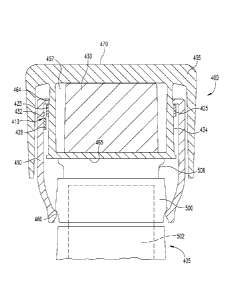
sensing
system of device 600 is configured to determine both the amount of the dose
set and the
amount of the dose delivered by operation of the device.
[0086] Other than for differences apparent from the following description and
associated
figures, device 600 can be configured the same as device too. The description
of device
600 includes further details of the configuration of its mechanical drive
assembly
corresponding to assembly 156 of device 100, as well as further details of the
sensing
system suited for mechanical drive assemblies of such type. Reference to parts
that are the
same as in device 100 use the same reference numbers as used with device 100
to facilitate
explanation.
[0087] With reference initially to Fig. 14, the device sensing system,
generally designated
620, is visible within a housing compartment 622 due to a portion of the
exterior main
housing 624 having been removed. Housing compartment 622 is shaped to receive
the
sensing system 620 and includes alignment ribs 644 and 646 that project
radially inward
Date Recue/Date Received 2020-12-04
CA 03046804 2019-06-11
WO 2018/111708 PCMJS2017/065247
-18-
to support core member 650 and maintain it rotationally and axially fixed
relative to the
housing 624.
[0088] Sensing system 620 is coupled to select members of device 600 which are
relatively rotatable in proportion to the amount of the set dose, and which
are relatively
rotatable in proportion to the amount of the injected or delivered dose. These
members
include barrel 660, drive sleeve 665 and core member 650.
[0089] With additional reference to Figs. 15 and 16, barrel 66o is a sleeve
that is keyed to
rotate with, but be axially movable relative to, tube 154. The drive sleeve
665 includes
external threading 670 that is engaged by internal threading of tube 154. An
internal axial
hollow 672 of drive sleeve 665 receives threaded shaft 165 therein. A not
shown keying
between drive sleeve 665 and threaded shaft 165 means that a rotation of drive
sleeve 665
within housing compartment 622 causes a corresponding rotation of shaft 165
which
advances that shaft axially to eject medication from the device 600.
[0090] During dose setting, as knob 152 and tube 154 are turned to screw out
axially
together from the device housing, barrel 660 rotates within the housing 624
about axis of
rotation 674 while drive sleeve 665 does not rotate about axis of rotation 674
due to a not
shown spline connection between the device housing 624 and drive sleeve 665.
[0091] When dose knob 152 is plunged by a user to deliver a dose, that
plunging initially
produces a transitioning translational movement of drive sleeve 665, due to an
axial force
transmitted by tube 154 at the external threading 670, which due to an axial
force
transmitted by sleeve flange 673 to barrel shoulder 675 causes a transitioning
translational
movement of barrel 660. This transitioning movement does not cause tube 154
and barrel
66o to rotate because a torque required to overcome a spring-biased, housing-
engaging
dose clicker (not shown) splined to barrel 660 is greater than the torque
generated at the
threading 670. This translational movement, occurring against a resistive
axial force
provided by the not shown clicker spring, moves splines 676 of barrel 66o
axially into
engagement with not shown complementary housing splines while releasing the
not shown
spline connection between the device housing and drive sleeve 665. Further
user plunging
of dose knob 152 causes drive sleeve 665 and thereby shaft 165 to rotate about
axis of
rotation 674, causing medicament to be ejected, while barrel 66o does not
rotate about
axis of rotation 674 due to its splined connection with the housing.
[0092] With additional reference to Figs. 17 and 18, sensing system 620
includes sensing
bands 68o and 700. Sensing band 68o includes a wiper sensing portion 682
formed in a
cylindrical sleeve shape, and a connector leg 684. The sensing portion 682 is
a single
CA 03046804 2019-06-11
WO 2018/111708 PCMJS2017/065247
-19-
assembled unit including two angularly staggered pairs of conductor-resistor
strips
extending circumferentially within the sleeve similarly to that described
above for sensing
bands iBoa and 1.80b. Alternatively sensing portion 682 can be constructed
similarly to
sensing band 180. Connector leg 684 contains the electrical leads circuited
with the
associated two conductor-resistor strip pairs. Connector leg 684 includes a
first region
686 that extends directly from the sensing portion 682 in an axial direction.
A transition
region 688 extends in the angular direction from first region 686 and
terminates in an end
region 690 that includes not shown electrical connections that can be a
printed extension
of lead end 228 and can be circuited with the electrical leads, such as a ZIF
(Zero Insertion
Force) connecter, that are circuited with the conductor-resistor strip pairs
of sensing
portion 682. The electrical connections are provided on the outer radial
periphery of end
region 690 for electrical connection during assembly with circuity routed to
the controller
of device 600. First region 686 is arranged in the same curved plane as
sensing portion
682, while transition region 688 juts outward from first region 686 in the
radial direction.
End region 690 extends from transition region 688 to lay over the core member
exterior
to enable electrical connection to the rest of the circuitry with the ability
to transition into
a flat connection.
[0093] Sensing band 700 includes a wiper sensing portion 702 formed in a
cylindrical
sleeve shape, and a connector leg 704. Wiper sensing portion 702 has a larger
diameter
than wiper sensing portion 682 to fit around it. Sensing band 700 is a single
assembled
unit including two angularly staggered pairs of conductor-resistor strips
extending
circumferentially within the sleeve similarly to that described above for
sensing bands
i8oa and i8ob, but typically with the conductor strips located radially
outward of their
respective resistor strips. Alternatively, sensing portion 702 can be
constructed similarly
to sensing band 1.80, with the resistor and conductor strips typically
reversed. Connector
leg 704 contains the electrical leads circuited with the associated two
conductor-resistor
strip pairs. Connector leg 704 includes a first region 706 that extends
directly from the
sensing portion 702 in an axial direction and in the same curved plane as
sensing portion
702. A transition region 708 extends in the angular direction from first
region 706 with an
offset to extend outward radially to allow a service loop to aide in
connection of 710 to
other circuitry. End region 710 of connector leg 704 extends in a curved shape
from
transition region 708 to lay over the core member exterior and includes not
shown
electrical connections, as previously described in relation to end region 690,
on its outer
CA 03046804 2019-06-11
WO 2018/111708 PCMJS2017/065247
-20-
radial periphery circuited with the electrical leads within the connector leg
704 and for
electrical connection during assembly with circuity routed to the controller
of device 600.
[0094] Core member 650 is formed in one-piece of a rigid plastic and includes
an interior
bore or hollow therethrough 652. Core member 650 has a sleeve portion 720 with
a
cylindrical, radially inner periphery or surface 722 and a cylindrical,
radially outer
periphery or surface 724. Core member 650 includes keyed portion 730 at the
distal end
of sleeve portion 720. Keyed portion includes a cylindrical, radially inner
surface 732 that
is an axial continuation of sleeve portion surface 722. The radially outer
surface 735 has
channeled sections 736 that fit over alignment ribs 644 and 646 to provide
alignment for
installation within the housing compartment 622 and to prevent core member 650
from
rotating or shifting axially within housing 624 during use. While core member
650 is
shown as a single piece that is effectively connected to the housing, such a
design is not
necessary but facilitates manufacture and assembly. In alternate embodiments,
a core
member can be integrally formed with the outer housing, or formed of multiple
parts
assembled together and then installed to the housing.
[0095] Sensing bands 68o and 700 are each mounted to core member 650 to be
rotationally and axially fixed with core member 650, and therefore indirectly
axially and
rotationally fixed with housing 624. Such mounting can be with adhesives, or
an alternate
manner such as mechanical fasteners or a friction fit.
[00961 Sensing band 680 is arranged such that wiper sensing portion 682 wraps
along
or layers the full circumference of the cylindrical radially inner surface
722, connector leg
first region 686 extends along cylindrical radially inner surface 732,
transition region 688
fits through a slot-shaped opening 740 provided through keyed portion 730 by a
notch 742
in its distal end 744, and end region 690 overlays radially outer surface 735.
[0097] Sensing band 700 is arranged such that wiper sensing portion 702 is
radially
aligned with and radially outward of wiper sensing portion 682 and directly
sandwiching
core sleeve portion 720 therebetween such that the two sensing layers provided
by sensing
bands 68o and 700 are separated only by core sleeve portion 720. Wiper sensing
portion
702 wraps along the full circumference of the cylindrical radially outer
surface 724, with
connector leg first region 706, transition region 708 and end region 710
overlaying radially
outer surface 735 of keyed portion 730.
[0098] A wiper element 750 coupled to drive sleeve 665 that extends through
core bore
652 is positioned radially inward of and slidingly engages wiper sensing
portion 682.
Wiper element 750 is rigid and has a suitable axial length to effectively
engage the wiper
CA 03046804 2019-06-11
WO 2018/111708 PCMJS2017/065247
-21-
sensing portion 682 at all times of device operation. Such a design allows the
drive sleeve
rotational position to be checked even when it should not be rotating during a
dose setting.
Wiper element 750 projects radially outward from a stepped arm 752 that
extends axially
from a C-shaped clip or mount 754. A cut-out or depression 675 in the
periphery of drive
sleeve 665 underneath the wiper element 750 and arm 752 serves as clearance
for arm 752
to flex.
[0099] Wiper element 750, arm 752 and clip 754 are shown integrally formed,
but can be
separately formed and assembled. The material of the arm 752 and clip 754 can
be a
pressed stainless steel that affords sufficient resiliency for a flexing of
arm 752, which
flexing provides a spring loaded engagement of wiper element 750 with sensing
band 680
as well as accounts for non-concentricity, and for attachment of clip 754 to
drive sleeve
665. Wiper clip 754, and therefore arm 752 and wiper element 750, are
rotationally and
axially fixed to drive sleeve 665 via a projection 758 of drive sleeve 665
that closely fits
within a complementary hole 760 in clip 754, with the resiliency of the C-
shaped clip 754
gripping around the drive sleeve 665 radially periphery. As shown in Fig, 19,
during
manufacturing assembly of clip 754 to drive sleeve 665, as clip 754 is axially
slid onto drive
sleeve 665 as shown at arrow 753, clip 754 is resiliently splayed open by
wedge feature 770,
allowing clip 754 to be moved axially so that hole 760 fits above and then
onto projection
758, at which axial position clip 754 has passed wedge feature 770 so as to
snap back
around the drive sleeve 665 to secure the clip as shown in Fig. 20.
[0100] A wiper element 780 coupled to barrel 66o is positioned radially
outward of and
slidingly engages wiper sensing portion 702. As shown in Fig. 16, the wiper
element 780
can extend in an axially different direction than the wiper element 750. As
shown in Fig.
16, the wiper element 780 can radially overlap the wiper element 750, being
separated by
the sidewall of the sleeve portion 720 of the core member 650. Wiper element
780 is
positioned radially outward from wiper element 750. Wiper element 780 is rigid
and has
a suitable axial length to effectively engage sensing band 700 at all times of
device
operation. Such a design allows the barrel rotational position to be checked
even when it
should not be rotating during a dose injection. Wiper element 780 projects
radially inward
from a stepped arm 782 that extends axially from a C-shaped clip 784. Wiper
element 780,
arm 782 and clip 784 are shown integrally formed, such as from pressed
stainless steel,
but can be separately formed and assembled. Arm 782 is flexible and provides a
spring
loaded engagement of wiper element 780 with sensing band 700 and to account
for non-
concentricity.
CA 03046804 2019-06-11
WO 2018/111708 PCMJS2017/065247
-22-
[0101] Wiper clip 784, and therefore arm 782 and wiper element 780, are
rotationally
fixed to barrel 66o by a keyed connection using a notch 790 in clip 784 and a
space 792
between the ends 793 of the two clip legs to closely receive two tangs 794
that project
inward within the hollow 798 of barrel 660. Wiper clip 784, and therefore arm
782 and
wiper element 780, are shown axially fixed to barrel 66o by axially extending,
detented
springs 797 that snap fit into indents 799 on the barrel interior surface, but
can be
alternatively secured such as using adhesive or mechanical fasteners, such as
radial
crimps.
[0102] As will be appreciated from an understanding of the operation of device
600
described above, the relationship of wiper element 780 with sensing band 700
allows a
rotation of the barrel 660 relative to the core member 650 and housing 624 to
be sensed
to allow a dose set for device 600 to be identified by a controller, and the
relationship of
wiper element 750 with sensing band 680 allows a rotation of the drive sleeve
665 relative
to the core member 650 and housing 624 to be sensed to allow a dose delivered
for device
600 to be identified by the controller.
[0103] Referring now to Figs. 23-25, there is shown pertinent parts of an
alternate
medication delivery device with sensing system. As with the device 600, the
device of Figs.
23-25 also is configured to determine both the amount of the dose set and the
amount of
the dose delivered by operation of the device. The device of Figs. 23-25 uses
a a modified
sensing band having different regions of common electrical strips cooperating
with a pair
of wiper elements. It will be appreciated that the device of Figs. 23-25 can
be similar in
overall operation to device 600.
[0104] The device includes a barrel 85o, a drive sleeve 86o that transmits its
rotation, via
a not shown mechanical drive train, to a not shown threaded shaft used to
eject medication,
and a core member 890 that is rotationally fixed to the device housing and
axially
unconstrained to the device housing such that it can slide axially relative to
the device
housing.
[0105] A wiper assembly, generally referenced at 88o, is fixedly coupled to
drive sleeve
860 to rotate and move axially therewith, and to extend within bore 898 of
core member
890. Wiper assembly 88o includes a pair of wipers 882 and 884, each formed of
a wiper
element on a flexible arm. The wiper elements of wipers 882 and 884 are shown
as
outwardly facing, convex surfaces projecting from the arms, but need not be so
shaped or
projecting. Wipers 882 and 884 extend axially from and are integrally formed
with a C-
shaped clip or mount 886 at locations 18o degrees apart from each other. Wiper
882
CA 03046804 2019-06-11
WO 2018/111708 PCMJS2017/065247
-23-
extends further axially from mount 886 than does wiper 884 as further
described below.
Wiper 882 can flex within depression 862 of drive sleeve 860 while wiper 884
similarly
can flex within a depression on the side of drive sleeve 860 opposite
depression 862. Wiper
mount 886 secures around axial portion 863 of drive sleeve 860 so that wiper
assembly
88o rotates with the drive sleeve, and wiper assembly 88o does not move
axially relative
to drive sleeve 860, such as due to the axial capture of wiper mount 886 via a
shoulder 861
formed on drive sleeve 86o and frictional interaction on the internal face of
wiper mount
886.
[0106] A wiper assembly, generally referenced at 870, is fixedly coupled in a
suitable
fashion to barrel 850 so as to rotate and move axially therewith . Wiper
assembly 870
includes a pair of wipers 872 and 874, each formed of a wiper element on a
flexible arm.
The wiper elements of wipers 872 and 874 are shown as strip-engaging surfaces
of their
respective wiper arms, but can project from such arms. Wipers 872 and 874
extend from
and are integrally formed with a wiper ring, which ring is shown as having
keys 876 that
closely fit within angular spaces between the opposite angular ends of arc-
shaped
extensions 854 of barrel 850. Wipers 872 and 874 are circumferentially
disposed relative
to one another substantially 180 degrees (that is, in a range of 180 degrees
plus/minus to
degrees). In one example, wipers 872 and 874 extend axially at locations 180
degrees apart
from each other. Wiper 874 extends further axially forward than does wiper 872
(that is,
axially offset from one another) as further described below.
[0107] Core member 890 is constrained to move axially with drive sleeve 86o
and barrel
850 when drive sleeve 860 and barrel 850 move together axially within the
device housing
during mode transitioning of the device. In the shown embodiment, core member
890 is
driven forward within the device housing by a thrust face of wiper assembly
870 when the
device transitions from dial mode to injection mode. Clip 920 is an axial
thrust washer/clip
that locks onto the drive sieve 86o and is used to pull core member 890 back
within the
device housing when the device returns to dial mode after being in injection
mode.
[colo8] Each of wiper assemblies 870 and 88o cooperates with a different
sensing band,
each of which sensing bands has a single pair of particularly shaped conductor-
resistor
strips extending therein that are shaped to have different regions be engaged
by the wiper
elements of the wiper assemblies. In particular, wiper assembly 870 cooperates
or
functions with a sensing band, generally designated 891, that wraps around the
exterior of
core member 890. Wiper assembly 88o cooperates with a sensing band shown in
cross
section in Fig. 24 and generally referenced 897 which wraps the interior of
core member
CA 03046804 2019-06-11
WO 2018/111708 PCMJS2017/065247
-24-
890. Each sensing band 891 and 897 is rotationally and axially fixed with core
member
890 and therefore indirectly rotationally fixed to the device housing. The
sensing bands
891 and 897 are mounted on the core member 890 similarly to the manner that
sensing
bands 680 and 700 fit within, around and through core member 650.
[0109] With additional reference to the flattened configuration of the sensing
band
shown in Fig. 25, the construction and design of sensing band 891 will be
further explained.
This explanation of sensing band 891 also applies to sensing band 897 which is
similarly
configured, though sensing band 891 works with wiper assembly 870 to sense
barrel
position while sensing band 897 works with wiper assembly 88o to sense drive
sleeve
position. Sensing band 891 is shown including a sensing portion 892 that holds
the
sensing strip pair and which when installed is in a cylindrical sleeve shape.
Connector leg
899 is used for making an electrical connection between the sensing strip pair
within
sensing portion 892 and the device controller.
[ono] The effective shape of the pair of conductor-resistor strips extending
within
sensing portion 892, and thereby the effective sensing area of sensing portion
892, is
shown in Fig. 25 in dashed lines. The sensing area includes a main path 893
and a
secondary path 902 that are different regions of the same electrical strips so
as to be
electrically integrated, thereby allowing the controller to receive a single
electrical output
from the sensing band 891 whether produced by the the main path 893 or the
secondary
path 902. Main path 893 continuously extends between angular ends 894 and 896.
Main
path 893 is axially positioned within the device to be axially operatively
aligned for contact
with the wiper element of wiper 872. Main path 893 is never contacted by wiper
874 as
barrel 850 is rotated during use. When sensing band 891 is installed around
core member
890, the main path 893 almost completely rings the core member periphery. The
only
periphery portion not ringed is a small angular region or gap 895 of that
periphery between
the facing angular ends 894 and 896. The device controller is able to
determine where
along the angular length of main path 893 the wiper element of wiper 872
operatively
contacts the main path 893, allowing a position of the barrel 86o relative to
the core
member 890 to be sensed to allow a dose set for the device to be identified by
the
controller.
[0111] Secondary path 902 continuously extends between angular ends 904 and
906 and
juts directly from main path 893 in the axially forward direction. Secondary
path 902 is
axially positioned within the device to be axially operatively aligned for
contact with the
wiper element of wiper 874, and is never contacted by wiper 872. Secondary
path 902 has
CA 03046804 2019-06-11
WO 2018/111708 PCMJS2017/065247
-25-
an angular length extending between ends 904 and 906 which covers the length
of the
angular gap 895. Secondary path 902 is positioned along the angular length of
main path
893 in view of the angular spacing beween the wiper elements of wipers 872 and
874 so as
to realize a design in which wiper 874 engages secondary path 902 at all times
wiper 874
is within angular gap 895 and not operatively contacting main path 893.
Secondary path
902 is shown positioned halfway along the angular length of main path 893 due
to wipers
872 and 874 begin spacedi8o degrees apart around the core member 890, but in
alternate
embodiments can be positioned differently to account for different angular
spacings of the
wipers. Alternatively, the secondary path 902 may be formed as a separate
second sensing
band (not shown) axially disposed adjacent to the main path 893 of the first
sensing band.
The separate second sensing band is contactedly associated with the wiper 874,
while the
first sensing band with main path 832 is contactecily associated with the
wiper 872.
[01121 The device controller recognizes barrel rotational position from the
single
electrical signal it receives from sensing band 891. During the majority of
barrel rotation,
the magnitude of the electrical signal to the device controller reflects where
the wiper 872
engages main path 893, during which time wiper 874 is not engaged with
secondary path
902. When wiper 872 enters the rotary gap 895 to no longer engage main path
893, the
wiper 874 simultanesously engages secondary path 902 to short the signal to
the controller
notably differently from where the signal was being shorted by wiper element
872
immedicately prior. This changed signal value, as well as the value of that
signal as it
further changes as the wiper 874 moves along the angularly length of secondary
path 902,
allows the controller to recognize barrel rotational position until the the
wiper 872 again
engages main path 893 while the wiper 874 moves off secondary path 902.
[0113] It will be appreciated that rather than being the same angular length
as gap 895,
secondary path 902 can have an angular length longer, such as a few degrees
longer, than
the angular length of gap 895. In such a design, while there would always be
at least one
wiper in contact with the sensing band for all possible rotational or angular
positions of
the relevant sensed member, there also will be certain rotational positions of
the sensed
member for which wiper 874 engages the few degrees longers section of the
secondary path
902 while wiper 872 also engages main path 893. At such certain rotational
positions, it
is appreciated that the single signal that sensing band 891 sends to the
device controller,
depending on the electrical configuration of the sensor, can introduce
uncertainty for the
controller, such as the output signal being generated by sensing band 891
being an
averaging of the signals otherwise sent by wipers 874 and 872 contacting their
respective
CA 03046804 2019-06-11
WO 2018/111708 PCMJS2017/065247
-26-
paths. This uncertainty can be resolved in the device by an initialization
action involving
active rotation of the wiper over a sufficiently large angular distance as to
provide the
controller with a continuous characteristic signal from sensing band 891 to
enable the
controller to resolve a known reference position.
[0114] While this invention has been shown and described as having preferred
designs,
the present invention can be modified within the spirit and scope of this
disclosure. For
example, module vo can sense dose setting amounts if adapted to work with a
device
portion having suitable parts that experience relative rotation during dose
setting. This
application is therefore intended to cover any variations, uses or adaptations
of the
invention using its general principles. Further, this application is intended
to cover such
departures from the present disclosure as come within known or customary
practice in the
art to which this invention pertains.
[0115] While the invention has been illustrated and described in detail in the
drawings
and foregoing description, the same is to be considered as illustrative and
not restrictive
in character. All changes, equivalents, and modifications that come within the
spirit of the
inventions defined by the claims included herein are desired to be protected.
[0116] Various aspects are described in this disclosure, which include, but
are not limited
to, the following aspects:
[0117] 1. A medication delivery device including: a first member and a second
member
rotatable relative to the first member about an axis of rotation in proportion
to at least one
of an amount of a dose set and an amount of a dose delivered by operation of
the
medication delivery device; a radially projected wiper coupled to the first
member; an
electrically operable sensing band coupled to the second member, the sensing
band
arranged in a curved shape and radially disposed relative to and in contacting
relationship
with the wiper, wherein, during relative rotation between the first and second
members,
the sensing band is operable to generate outputs associated with the relative
angular
position of the wiper along an operational angular length of the sensing band
that is
indicative of relative rotational positions of the first and second members;
and a controller
electrically coupled with the sensing band to determine, based on t he outputs
generated
by the sensing band, at least one of the amount of the dose set and the amount
of the dose
delivered by operation of the medication delivery device.
[0118] 2. The medication delivery device of aspect 1, further including a
radially projected
second wiper coupled to the first member, and an electrically operable second
sensing
band coupled to the second member, the second sensing band arranged in a
curved shape
CA 03046804 2019-06-11
WO 2018/111708 PCMJS2017/065247
-27-
and radially disposed relative to and in a contacting relationship with the
second wiper,
wherein the second sensing band is disposed axially relative to the sensing
band, wherein,
during relative rotation between the first and second members, the second
sensing band
is operable to generate outputs associated with the relative angular position
of the second
wiper along an operational angular length of the second sensing band that is
indicative of
relative rotational positions of the first and second members, wherein the
controller is
electrically coupled with the second sensing band to determine, based on the
outputs
generated by the second sensing band, at least one of the amount of the dose
set and the
amount of the dose delivered by operation of the medication delivery device.
Long] 3. The medication delivery device of aspect 2, where the second wiper
extends
axially further than the first wiper.
[0120] 4. The medication delivery device of aspect 4, where the sensing band
configured
to accommodate the first and second wipers.
[0121] 5. The medication delivery device of any one of aspects 2-4, where the
second wiper
is circumferentially disposed relative to the first wiper by substantially 180
degrees.
[0122] 6. A medication delivery device including: a first member and a second
member
rotatable relative to the first member about an axis of rotation in proportion
to an amount
of a dose set by operation of the medication delivery device; a third member
and a fourth
member rotatable relative to the third member about the axis of rotation in
proportion to
an amount of a dose delivered by operation of the medication delivery device;
a first wiper
coupled to the first member and projecting in a radial direction; a second
wiper coupled to
the third member and projecting in a radial direction; an electrically
operable first sensing
band coupled to the second member; an electrically operable second sensing
band coupled
to the fourth member, each of the first and second sensing bands arranged in a
curved
shape and radially disposed relative to and in a contacting relationship with
the first and
second wipers, respectively, wherein, during relative rotation between the
first and second
members and relative rotation between the third and fourth members, each of
the first and
second sensing bands is operable to generate outputs associated with the
relative angular
position of the corresponding first and second wipers along an operational
angular length
of the respective first and second sensing bands that is indicative of
relative rotational
positions of the first and second members and the third and fourth members;
and a
controller electrically coupled with each of the first and second sensing
bands to
determine, based on the outputs generated by the first and second sensing
bands, the
CA 03046804 2019-06-11
WO 2018/111708 PCMJS2017/065247
-28-
amount of the dose set and the amount of the dose delivered by operation of
the medication
delivery device.
[0123] 7. The medication delivery device of aspect 6, wherein the second
member and the
fourth member are integrally formed as a single core member.
[0124] 8. The medication delivery device of any one of aspects 6-7, further
including a
pair of first wipers coupled to the first member and a pair of second wipers
coupled to the
third member.
[0125] 9. The medication delivery device of aspect 8, further including a pair
of
electrically operable first sensing bands coupled to the second member and
associated with
the pair of first wipers; and a pair of electrically operable second sensing
bands coupled to
the fourth member and associated with the pair of second wipers.
[0126] 10. A medication delivery device including: a first member of the
medication
delivery device; a second member of the medication delivery device rotatable
relative to
the first member in proportion to at least one of an amount of a dose set and
an amount of
a dose delivered by operation of the medication delivery device, the first and
second
members relatively rotatable about an axis of rotation extending in an axial
direction; a
sensing system operable to detect relative rotational positions of the first
and second
members and generate outputs correlated to such relative rotational positions,
the sensing
system including: a wiper rotationally coupled to the first member and
projecting in a
radial direction; a sensing band rotationally coupled to the second member and
circuited
with an electrical power source, the sensing band arranged in a curved shape
around the
axis of rotation and having an operational angular length, the sensing band
disposed in the
radial direction inward or outward of the wiper for a physical contact with
the wiper as the
second member rotates relative to the first member, the sensing band having an
electrical
characteristic correlated with where along the operational angular length of
the sensing
band is operationally engaged in the radial direction due to the physical
contact with the
wiper; and a controller electrically circuited with the sensing system to
identify, based on
outputs of the sensing system, at least one of the amount of the dose set and
the amount
of the dose delivered by operation of the medication delivery device.
[0127] 11. The medication delivery device of aspect 10, wherein at least one
of the wiper
and the sensing band is radially resilient to assist the maintenance of the
wiper and the
sensing band in physical contact as the second member rotates relative to the
first member.
[0128] 12. The medication delivery device of any one of aspects 10-11, wherein
at least one
of the wiper and the sensing band is radially biased relative to the first and
second
CA 03046804 2019-06-11
WO 2018/111708 PCMJS2017/065247
-29-
members to which each is respectively rotationally coupled to assist the
maintenance of
the wiper and the sensing band in physical contact as the second member
rotates relative
to the first member.
[0129] 13. The medication delivery device of any one of aspects 10-12, wherein
the sensing
band is disposed radially outward of the wiper.
[0130] 14. The medication delivery device of of any one of aspects 10-13,
wherein the
second member comprises a housing of the medication delivery device.
[0131] 15. The medication delivery device of aspect 14, wherein the sensing
band is
attached directly to an interior circumferential surface of the housing.
[0132] 16. The medication delivery device of aspect 14, wherein the sensing
band is
disposed on a component that is at least rotatably fixedly mounted to the
housing.
[0133] 17. The medication delivery device of any one of aspects to-16, wherein
the
operational angular length extends only partially around a circumference of
the second
member.
[0134] 18. The medication delivery device of aspect 17, wherein the
operational angular
length extends at least 345 degrees but less than 360 degrees around an inner
circumference of the second member.
[0135] 19. The medication delivery device of any one of aspects io-18, wherein
the sensing
system comprises a second wiper rotationally coupled to the first member and
projecting
in the radial direction, and a second sensing band rotationally coupled to the
second
member and the electrical power source, the second sensing band arranged in a
curved
shape around the axis of rotation and having an operational angular length,
the second
sensing band disposed in the radial direction inward or outward of the second
wiper for a
physical contact with the second wiper as the second member rotates relative
to the first
member, the second sensing band having an electrical characteristic correlated
with where
along the operational angular length of the second sensing band is engaged in
the radial
direction due to the physical contact with the second wiper.
[0136] 20. The medication delivery device of aspect 19, wherein the
operational angular
lengths of the sensing band and the second sensing band are axially spaced and
each only
partially extends around a circumference of the second member.
[0137] 21. The medication delivery device of aspect 20, wherein the wiper and
the second
wiper comprise different regions of a single wiper body.
[0138] 22. The medication delivery device of any one of aspects 10-21, wherein
the
sensing system and the controller are parts of a reusable dose delivery
detection module,
CA 03046804 2019-06-11
WO 2018/111708 PCMJS2017/065247
-30-
the reusable dose delivery detection module removable from the first member
and the
second member for subsequent mounting to corresponding members of another
medication delivery device for use therewith.
[0139] 23. The medication delivery device of any one of aspects 10-22, wherein
the
sensing band is disposed radially outward of the wiper, the first electrical
strip including a
resistor strip and the second electrical strip including a conductor strip,
the conductor strip
disposed radially inward of the resistor strip and bendable radially outward
into electrical
contact with the resistor strip at an angular location at which the conductor
strip is engaged
by the wiper.
[0140] 24. The medication delivery device of any one of aspects 10-23, wherein
the
second member comprises a core member having an interior surface defining a
bore in
which the first member rotates, the sensing band layering the interior
surface.
[01411 25. The medication delivery device of aspect 24, wherein the core
member includes
an exterior surface and an opening extending between the interior surface and
the exterior
surface, the sensing band including a connector leg having electrical leads
passing through
the opening and wrapping along the exterior surface.
[0142] 26. The medication delivery device of aspect 24, wherein the sensing
band is a first
sensing band and the wiper is a first wiper, and further including a third
member of the
medication delivery device rotatable relative to the core member about the
axis of rotation
in proportion to at least one of an amount of a dose set and an amount of a
dose delivered
by operation of the medication delivery device, the sensing system further
including a
second wiper rotationally coupled to the third member and projecting inward or
outward
in the radial direction, and a second sensing band rotationally coupled to the
core member,
the second sensing band wrapping along a surface of the core member for
operational
contact with the second wiper as the third member rotates relative to the core
member, the
second sensing band having an electrical characteristic correlated with where
the second
sensing band is operationally engaged by the second wiper.
[0143] 27. The medication delivery device of aspect 26, wherein the first and
second
sensing bands directly sandwich the core member therebetween.
[0144] 28. The medication delivery device of aspect 26, wherein the second
sensing band
is positioned at a location in the radial direction between the first sensing
band and the
second wiper.
[0145] 29. The medication delivery device of aspect 24, wherein the core
member is
separately formed and rotatably fixed to a housing of the medication delivery
device.
CA 03046804 2019-06-11
WO 2018/111708 PCMJS2017/065247
-31-
[0146] 30. A medication delivery device for delivering medication from a
cartridge having
a barrel holding the medication between a movable plunger and an outlet, the
medication
delivery device including: a main housing; a cartridge housing for holding the
cartridge
extending from the main housing; a drive member including a forward end for
engaging
the movable plunger, the drive member having a length extending in an axial
direction
within the main housing; a dose delivery mechanism for controlling advancement
of the
drive member forward within the main housing in the axial direction to move
the movable
plunger for delivering medication through the outlet, the dose delivery
mechanism
including a first member rotatable relative to the main housing in proportion
to one of an
amount of a dose set and an amount of a dose delivered by operation of the
medication
delivery device, the first member relatively rotatable to the main housing
about an axis of
rotation extending in the axial direction; a sensing system operable to detect
relative
rotational positions of the first member and the main housing and generate
outputs
correlated to such relative rotational positions, the sensing system
including; a first wiper
coupled to the first member and projecting in a radial direction; a first
sensing band
coupled to the main housing, the first sensing band arranged in a curved shape
around the
axis of rotation and having a first operational angular length, the first
sensing band
disposed in the radial direction inward or outward of the first wiper for a
physical contact
with the first wiper during rotation of the first member relative to the main
housing, the
first sensing band having an electrical characteristic correlated with where
along the first
operational angular length the first sensing band is operationally engaged in
the radial
direction due to the physical contact with the first wiper; and a controller
in electrical
communication with the sensing system to identify, based on outputs of the
sensing
system, at least one of the amount of the dose set and the amount of the dose
delivered by
operation of the medication delivery device.
[0147] 31. The medication delivery device of aspect 30, wherein the first
sensing band is
rotationally coupled to the main housing via a core member, the core member
being
separately formed and rotatably fixed to the main housing.
[0148] 32. The medication delivery device of aspect 31, wherein the first
sensing band is
disposed on the core member and the core member is axially movable within the
main
housing, the first wiper fixedly coupled to the first member to move axially
therewith, the
first member axially movable within the main housing during operation of the
medication
delivery device, and wherein the core member and the first sensing band are
constrained
CA 03046804 2019-06-11
WO 2018/111708 PCMJS2017/065247
-32-
to move axially with the first member to maintain alignment of the first wiper
with the first
sensing band.
[0149] 33. The medication delivery device of aspect 30, wherein the first
sensing band is
rotationally coupled to the main housing via a core member having an interior
surface
defining a bore in which the first member is rotationally disposed, the first
sensing band
wrapping along the interior surface and disposed in the radial direction
outward of the
first wiper.
[0150] 34. The medication delivery device of aspect 33, further including a
second
member of the medication delivery device rotatable relative to the core member
about the
axis of rotation in proportion to the other of the amount of a dose set and
the amount of a
dose delivered by operation of the medication delivery device, the sensing
system firrther
including a second wiper rotationally coupled to the second member and
projecting inward
in the radial direction, and a second sensing band rotationally coupled to the
main housing
via the core member and circuited with the electrical power source, the second
sensing
band arranged in a curved shape around the axis of rotation and having a
second
operational angular length, the second sensing band wrapping along an exterior
surface of
the core member and disposed in the radial direction inward of the second
wiper for a
physical contact with the second wiper as the second member rotates relative
to the main
housing, the second sensing band including a third electrical strip and a
fourth electrical
strip being in electrical contact along the second operational angular length
where the
second sensing band is operationally engaged in the radial direction due to
physical
contact with the second wiper, the third electrical strip and the fourth
electrical strip being
spaced in the radial direction and out of electrical contact along the second
operational
angular length where the second sensing band is not operationally engaged in
the radial
direction due to physical contact with the second wiper, the second sensing
band having
an electrical characteristic correlated with where along the second
operational angular
length the second sensing band is operationally engaged in the radial
direction due to the
physical contact with the second wiper.
[0151] 35. The medication delivery device of aspect 34, wherein the first
sensing band
includes a first electrical strip and a second electrical strip being in
electrical contact along
the first operational angular length where the first sensing band is
operationally engaged
in the radial direction due to physical contact with the first wiper, the
first electrical strip
and the second electrical strip being spaced in the radial direction and out
of electrical
contact along the first operational angular length where the first sensing
band is not
CA 03046804 2019-06-11
WO 2018/111708 PCMJS2017/065247
-33-
operationally engaged in the radial direction due to physical contact with the
first wiper,
wherein the first and second sensing bands directly sandwich the core member
therebetween.
[0152] 36. The medication delivery device of aspect 35, wherein the first and
second
electrical strips include a main portion and a secondary portion, the
secondary portion
jutting directly from the main portion in the axial direction, the first wiper
being in an axial
position to engage the main portion but not the secondary portion, and wherein
the
sensing system comprises a second wiper in an axial position to engage the
secondary
portion but not the main portion.
[0153] 37. The medication delivery device of any one of aspects 34-36, wherein
the first
wiper and the second wiper are angularly spaced about the axis of rotation.
[0154] 38. The medication delivery device of any one of aspects 34-37, where
the second
wiper extends axially further than the first wiper.
[0155] 39. The medication delivery device of any one of aspects 34-38, where
the second
wiper is circumferentially disposed relative to the first wiper by
substantially 180 degrees.
[0156] 40. The medication delivery device of any one of aspects 30-39, further
including
a pair of first wipers coupled to the first member, and a pair of first
sensing bands coupled
to the main housing in physical contact with the respective first wipers.