Note: Descriptions are shown in the official language in which they were submitted.
CA 03046849 2019-06-11
WO 2018/119367 PCT/US2017/068126
METHODS AND APPARATUS FOR MAGNETIC MULTI-BEAD ASSAYS
CROSS REFERENCE TO RELATED APPLICATION
[0001] This application claims priority from U.S. Provisional Patent
Application No. 62/438,593 filed on December 23, 2016 entitled METHODS AND
APPARATUS FOR MAGNETIC MULTI-BEAD ASSAYS, which is hereby
incorporated by reference.
GOVERNMENT SUPPORT
[0002] This invention was made with government support under contract
= number HR0011-14-C-0020 awarded by the Defense Advanced Research Projects
Agency of the Department of Defense. The government has certain rights in the
invention.
BACKGROUND
[0003] Enzyme linked immunosorbent assay (ELISA) has been an industry
wide standard research technique used for measuring protein analytes from
biological matrices since its introduction in the 1960s. In its basic
conception, two
antibodies (immunoglobulins) are used to capture a single protein analyte. The
resulting immunocomplex is identified and measured using an enzyme and
reporter
buffer. The enzyme is typically bound to one of the antibodies through
covalent
binding. The enzyme, when incubated in the presence of the reporter buffer,
converts the substrate to a functional reporter which can be measured
analytically
by spectrophotometric means.
[0004] Current state of the art ELISA-related technologies are replacing the
plate-based format with a single-bead-based format. Single-bead-based ELISAs
have one antibody that is bound to a solid surface, typically a bead, and the
second
antibody is labeled with biotin. The capture bead contains material that
allows it to
be easily manipulated by an applied magnetic field, including separating the
bead
and any analytes bound to the bead from a sample suspension. This process,
called magnetic separation, is well known in the art and may be used to
concentrate the target analyte and to remove unbound material such as unwanted
proteins that may contribute to signal background. Compared to traditional
1
CA 03046849 2019-06-11
1 s
WO 2018/119367 PCT/US2017/068126
ELISAs, single-bead-based ELISAs can provide improved sensitivity to target
analytes with lower background and in a shorter amount of time.
[0005] Nevertheless, there is a need for continuing improvement in sensitivity
and specificity to target analytes.
BRIEF SUMMARY
[0006] Various embodiments disclosed herein relate to methods and
apparatus for detecting a complex including an analyte in a sample by
observing
complexes containing two or more distinguishable beads (i.e., beads of
different
types) that are bound by the analyte. In accordance with one or more
embodiments, a bead-based magnetic assay system for detecting a complex
including an analyte based on optically detected magnetic resonance (ODMR)
includes a plurality of functionalized beads of a first type, which are
magnetic
functionalized beads and are functionalized to include a first moiety that
associates
with an analyte under suitable conditions, a plurality of functionalized beads
of a
second type, which are functionalized to include a second moiety that
associates
with the analyte under suitable conditions, a substrate including at least one
ODMR
center, a light source configured to generate incident light that excites
electrons
within the at least one ODMR center from a ground state to an excited state, a
magnet for applying a bias magnetic field on a complex disposed over the at
least
one ODMR center, the complex including one of the first type of functionalized
bead, the analyte, and one of the second type of functionalized bead. The
system
further includes a microwave source configured to generate a microwave field
incident on the at least one ODMR center, the microwave source being further
configured to generate the microwave field with frequencies that correspond to
ground state transitions in the at least one ODMR center, in which the at
least one
ODMR center produces emitted light when illuminated by the incident light,
characteristics of the emitted light being influenced by the microwave field
and by
the magnetic functionalized bead associated with the analyte in the complex,
and
an optical photodetector that detects light emitted by the at least one ODMR
center. In some embodiments, the at least one ODMR center can be a silicon
vacancy center in a silicon carbide lattice. In other embodiments, the at
least one
ODMR center can be a silicon vacancy center in a diamond lattice. In still
other
embodiments, the at least one ODMR center can be a nitrogen-vacancy center in
a
2
CA 03046849 2019-06-11
WO 2018/119367 PCT/US2017/068126
diamond lattice. In certain embodiments, the at least one ODMR center can be
formed in an upper surface of the substrate. In some embodiments, the at least
one ODMR center can be a plurality of ODMR centers formed in the upper surface
of the substrate. In these embodiments, the optical photodetector can be an
optical imaging system having an imaging sensor that images the emitted light
from
the plurality of ODMR centers. In certain embodiments, each of the first and
the
second moiety can be a receptor, protein, antibody, cell, virus, or nucleic
acid
sequence. In some embodiments, the functionalized beads of the first type can
be
superparamagnetic functionalized beads including a superparamagnetic material.
In certain embodiments, the functionalized beads of the first type can include
a
nonmagnetic layer encapsulating the superparamagnetic material. In some
embodiments, the superparamagnetic functionalized beads can include iron oxide
particles. In certain embodiments, the functionalized beads of the first type
can
comprise magnetic nanoparticles disposed within a polymer substrate. In other
embodiments, the functionalized beads of the first type can comprise magnetic
nanoparticles disposed on a surface of a polymer substrate. In some
embodiments, the functionalized beads of the second type can be fluorescent
functionalized beads. In other embodiments, the functionalized beads of the
second type can be magnetic functionalized beads including a quantity of
magnetic
material distinguishable from the functionalized beads of the first type. In
still other
embodiments, the functionalized beads of the second type can be magnetic
functionalized beads, the second type of functionalized beads including a
magnetic
property distinguishable from the functionalized beads of the first type. In
some
embodiments, the functionalized beads of the first type can be
superparamagnetic
functionalized beads including a superparamagnetic material. In certain
embodiments, the functionalized beads of the first type can include a
nonmagnetic
layer encapsulating the superparamagnetic material. In some embodiments, the
functionalized beads of the second type can be ferromagnetic functionalized
beads
including a ferromagnetic material. In certain embodiments, the functionalized
beads of the second type can include a nonmagnetic layer encapsulating the
ferromagnetic material. In some embodiments, each of the first type of
functionalized beads and the second type of functionalized beads can have a
diameter in a range of between 50 nm and 10 gm. In certain embodiments, each
3
CA 03046849 2019-06-11
WO 2018/119367 PCT/US2017/068126
of the diameters of the functionalized beads of the first type and the second
type
can be in a range of between 0.5 pm and 5 pm. In some embodiments, the
diameter of the functionalized beads of the first type can be similar to the
diameter
of the functionalized beads of the second type. In other embodiments, the
diameter of the functionalized beads of the first type can be different from
the
diameter of the functionalized beads of the second type by at least 50%. In
some
embodiments, the system can further include a plurality of functionalized
beads of
at least a third type, functionalized to include at least the second moiety
that
associates with at least a second analyte under suitable conditions. In
certain
embodiments, the system can further include a plurality of functionalized
beads of
a fourth type, functionalized to include the second moiety that associates
with the
second analyte under suitable conditions. In some embodiments, the
functionalized beads of the first and/or second type can further include at
least one
additional moiety that associates with the second analyte under suitable
conditions.
In certain embodiments, the system can further include a third moiety that
associates with a third analyte under suitable conditions, wherein the
functionalized
beads of the first type are further functionalized to include the second
moiety, and
the functionalized beads of the second type are further functionalized to
include the
third moiety.
[0007] In accordance with one or more embodiments, a method of detecting
a complex including an analyte includes contacting a sample in a solution with
a
population of functionalized beads of a first type, which are magnetic
functionalized
beads and are functionalized to include a first moiety that associates with an
analyte under suitable conditions, contacting the sample solution with a
population
of functionalized beads of a second type, which are functionalized to include
a
second moiety that associates with the analyte under suitable conditions,
contact
resulting in formation of a complex including one of the first type of
functionalized
bead, the analyte, and one of the second type of functionalized bead, and
detecting
the complex including the analyte by detecting magnetic fields produced by the
magnetic functionalized bead and by detecting the functionalized bead of the
second type associated with the analyte in the complex. In some embodiments,
the method can further include disposing the sample solution including the
complex
over a substrate that includes at least one optically detected magnetic
resonance
4
CA 03046849 2019-06-11
WO 2018/119367 PCT/1JS2017/068126
(ODMR) center formed in the substrate, exciting electrons within the at least
one
ODMR center from a ground state to an excited state with incident light,
applying a
bias magnetic field on the complex, and generating a microwave field incident
on
the at least one ODMR center, the microwave field including frequencies that
correspond to ground state transitions in the at least one ODMR center,
wherein
detecting the complex including the analyte further includes analyzing light
emitted
by the at least one ODMR center, characteristics of the emitted light being
influenced by the microwave field and by the magnetic functionalized bead
associated with the analyte in the complex. In some embodiments, the at least
one
ODMR center can be a nitrogen-vacancy center in a diamond lattice. In certain
embodiments, the at least one ODMR center can be formed in an upper surface of
the substrate. In some embodiments, the at least one ODMR center can be a
plurality of ODMR centers formed in the upper surface of the substrate. In
these
embodiments, analyzing light emitted by the plurality of ODMR centers includes
imaging the emitted light. In certain embodiments, the method can further
include
applying a magnetic field gradient to the sample solution after contacting the
sample with the population of functionalized beads of the first type. In some
embodiments, applying the magnetic field gradient to the sample solution can
be
performed after contacting the sample solution with the population of
functionalized
beads of the second type. In certain embodiments, the population of
functionalized
beads of the first type and the population of functionalized beads of the
second
type can be added to the sample solution sequentially. In some embodiments,
the
functionalized beads of the second type can be fluorescent functionalized
beads,
and the method can further include illuminating the complex with incident
light that
excites fluorescence within the functionalized beads of the second type and
fluorescence imaging of the complex. In other embodiments, the functionalized
beads of the second type can be magnetic functionalized beads, including a
magnetic property distinguishable from the functionalized beads of the first
type. In
some embodiments, the method can further include applying a magnetic field
gradient to the sample solution after contacting the sample solution with the
functionalized beads of the first and second types. In certain embodiments,
the
method can further include varying the magnetic field gradient applied to the
sample solution. In some embodiments, the method can further include
CA 03046849 2019-06-11
WO 2018/119367 PCT/US2017/068126
concentrating the sample solution after contacting the sample solution with
the
population of functionalized beads of the second type. In certain embodiments,
the
method can further include agglomerating a plurality of functionalized beads
of the
first and second types, after contacting the sample solution with the
population of
functionalized beads of the second type, before detecting the complex. In some
embodiments, the method can further include dehydrating the sample solution
after
disposing the sample solution over the diamond substrate.
[0008] In accordance with one or more embodiments, a bead-based assay
system for detecting a complex including an analyte includes a plurality of
functionalized beads of a first type, which are magnetic functionalized beads
and
are functionalized to include a first moiety that associates with an analyte
under
suitable conditions, a plurality of functionalized beads of a second type,
which are
fluorescent functionalized beads, and are functionalized to include an
unlabeled
moiety that associates with the analyte under suitable conditions, a light
source
configured to generate incident light that excites fluorescence within the
functionalized beads of the second type, and an optical fluorescence detector
that
detects fluorescence emitted by the functionalized beads of the second type
associated with the analyte in a complex including one of the first type of
functionalized bead, the analyte, and one of the second type of functionalized
bead. In certain embodiments, the fluorescent functionalized beads can
comprise
a polymer substrate impregnated with a fluorescent material. In some
embodiments, the optical fluorescence detector can include a
spectrophotometer.
In other embodiments, the optical fluorescence detector can include an optical
imaging sensor that images the fluorescence emitted by the functionalized
beads
of the second type associated with the analyte in the complex. In some
embodiments, the functionalized beads of the first type can be
superparamagnetic
functionalized beads. In certain embodiments, the superparamagnetic
functionalized beads can include iron oxide particles. In some embodiments,
the
functionalized beads of the first type can include magnetic nanoparticles
disposed
within the polymer substrate. In other embodiments, the functionalized beads
of
the first type can include magnetic nanoparticles disposed on a surface of the
polymer substrate.
6
CA 03046849 2019-06-11
WO 2018/119367 PCT/US2017/068126
[0009] In accordance with one or more embodiments, a method of detecting
a complex including an analyte includes contacting a sample in a solution with
a
population of functionalized beads of a first type, which are magnetic
functionalized
beads and are functionalized to include a first moiety that associates with an
analyte under suitable conditions, contacting the sample solution with a
population
of functionalized beads of a second type, which comprise a polymer substrate
impregnated with a fluorescent material, and are functionalized to include an
unlabeled moiety that associates with the analyte under suitable conditions,
contact
resulting in formation of a complex including one of the first type of
functionalized
bead, the analyte, and one of the second type of functionalized bead,
illuminating
the complex with incident light that excites fluorescence within the
functionalized
beads of the second type, and detecting the complex including the analyte by
analyzing fluorescence emitted by the functionalized beads of the second type
associated with the analyte in the complex. In some embodiments, the method
can
further include applying a magnetic field gradient to the sample solution
after
contacting the sample with the population of functionalized beads of the first
type.
In certain embodiments, applying the magnetic field gradient to the sample
solution
can be performed after contacting the sample solution with the population of
functionalized beads of the second type. In some embodiments, the method can
further include concentrating the sample solution after contacting the sample
solution with the population of functionalized beads of the second type,
before
detecting the complex. In certain embodiments, the method can further include
agglomerating a plurality of functionalized beads of the first and second
types, after
contacting the sample solution with the population of functionalized beads of
the
second type, before detecting the complex. In some embodiments, the method
can further include dehydrating the sample solution before detecting the
complex.
[0010] Magnetic multi-bead assays improve upon bead-based ELISAs by
detecting target analytes bound in complexes, such as immunocomplexes. By
combining the convenience and simplicity of magnetic separation with robust
and
sensitive detection of beads, magnetic multi-bead assays provide excellent
sensitivity with a simple, rapid process.
7
CA 03046849 2019-06-11
WO 2018/119367 PCT/US2017/068126
BRIEF DESCRIPTION OF THE DRAWINGS
[0011] The foregoing will be apparent from the following more particular
description of example embodiments, as illustrated in the accompanying
drawings
in which like reference characters refer to the same parts throughout the
different
views. The drawings are not necessarily to scale, emphasis instead being
placed
upon illustrating embodiments.
[0012] FIG. 1A schematically illustrates a functionalized bead of a first
type, a
first moiety, a functionalized bead of a second type, a second moiety, and an
analyte in accordance with one or more embodiments.
[0013] FIG. 1B schematically illustrates a complex that includes one of a
functionalized bead of a first type, a first moiety, one of a functionalized
bead of a
second type, a second moiety, and an analyte in accordance with one or more
embodiments.
[0014] FIG. 1C schematically illustrates a bead-based assay system for
detecting a complex including a spectrophotometer that detects fluorescence
emitted by the functionalized beads of the second type in accordance with one
or
more embodiments.
[0015] FIG. 1D illustrates a plot of relative fluorescence units (RFU) as a
function of PSA (pM) in accordance with one or more embodiments.
[0016] FIG. 2 illustrates a method of detecting a complex including an analyte
in accordance with one or more embodiments.
[0097] FIG. 3A schematically illustrates a bead-based assay system for
detecting a complex including an optical imaging sensor that images
fluorescence
emitted by the functionalized beads of the second type in accordance with one
or
more embodiments.
[0018] FIG. 3B illustrates a fluorescent image in accordance with one or more
embodiments.
[0019] FIG. 3C illustrates a plot of signal as a function of PSA concentration
(pM) in accordance with one or more embodiments.
CA 03046849 2019-06-11
r
WO 2018/119367 PCT/US2017/068126
[0020] FIG. 4 illustrates another method of detecting a complex including an
analyte in accordance with one or more embodiments.
[0021] FIG. 5 schematically illustrates a wide-field diamond magnetic imaging
apparatus in accordance with one or more embodiments.
[0022] FIG. 6A schematically illustrates several complexes including
magnetic beads and fluorescent beads in accordance with one or more
embodiments.
[0023] FIG. 6B illustrates a fluorescent image of the complexes shown in
FIG. 6A in accordance with one or more embodiments.
[0024] FIG. 6C illustrates a magnetic image of the complexes shown in FIG.
6A in accordance with one or more embodiments.
[0025] FIG. 7A schematically illustrates a complex that includes a magnetic
functionalized bead of a first type, a magnetic functionalized bead of a
second type,
and an analyte in accordance with one or more embodiments.
[0026] FIG. 7B schematically illustrates a complex including magnetic beads
of the first and second types in accordance with one or more embodiments.
[0027] FIG. 7C illustrates a positive magnetic image of the magnetic beads
shown in FIG. 78 in accordance with one or more embodiments.
[0028] FIG. 70 illustrates a negative magnetic image of the magnetic beads
shown in FIG. 7B in accordance with one or more embodiments.
[0029] FIG. 8A illustrates magnetic bead discrimination based on remanence
and susceptibility in accordance with one or more embodiments.
[0030] FIG. 8B illustrates magnetic bead discrimination based on
magnetization magnitude in accordance with one or more embodiments.
[0031] FIG. 8C illustrates magnetic bead discrimination based on magnetic
anisotropy in accordance with one or more embodiments.
[0032] FIG. 8D illustrates magnetic bead discrimination based on magnetic
coercivity in accordance with one or more embodiments.
[0033] FIG. 8E illustrates magnetic bead discrimination based on AC
magnetic response in accordance with one or more embodiments.
9
_
CA 03046849 2019-06-11
WO 2018/119367 PCT/US2017/068126
[0034] FIG. 8F illustrates magnetic bead discrimination based on magnetic
saturation in accordance with one or more embodiments.
[0035] FIG. 9 illustrates a magnetic image of two beads of different sizes in
accordance with one or more embodiments.
[0036] FIGS. 10A-1, 10B-1, and 10C-1 illustrate magnetic images of the
image signal of three beads B in accordance with one or more embodiments.
[0037] FIGS. 10A-2, 10B-2, and 10C-2 illustrate magnetic images of the
difference signal after subtracting the characteristic signal of three beads B
in
accordance with one or more embodiments.
[0038] FIGS. 11A-1, 11B-1, and 11C-1 illustrate magnetic images of the
image signal of three dimers of beads A and B in accordance with one or more
embodiments.
[0039] FIGS. 11A-2, 11B-2, and 11C-2 illustrate magnetic images of the
difference signal of three dimers beads A and B after subtracting the
characteristic
bead B signal in accordance with one or more embodiments.
[0040] FIG. 12A schematically illustrates a multiplexed assay including four
distinguishable bead types in accordance with one or more embodiments.
[0041] FIG. 12B schematically illustrates complexes including four
distinguishable bead types in accordance with one or more embodiments.
[0042] FIG. 13A schematically illustrates a multiplexed assay including three
distinguishable bead types in accordance with one or more embodiments.
[0043] FIG. 13B schematically illustrates complexes including three
distinguishable bead types in accordance with one or more embodiments.
DETAILED DESCRIPTION
[0044] As stated above, various embodiments disclosed herein relate to
methods and apparatus for detecting a complex including an analyte in a sample
by observing complexes containing two or more distinguishable beads (i.e.,
beads
of different types) that are bound by the analyte. At least one of the bead
types is
magnetic and can be concentrated in a liquid suspension by means of magnetic
forces exerted with an applied magnetic field. A fully-magnetic assay may also
be
CA 03046849 2019-06-11
WO 2018/119367 PCT/US2017/068126
implemented by using diamond magnetic imaging to distinguish between magnetic
bead types with distinct magnetic properties.
[0045] In accordance with one or more embodiments, wide-field magnetic
imaging using nitrogen-vacancy (NV) centers in diamond can be used to provide
a
platform on which to implement a multi-bead assay that is fully magnetic,
eliminating the need to detect fluorescence from the sample. Magnetic beads
provide strong, stable signals by means of the magnetic fields they produce,
which
permeate through biological sample matrices and contaminants and allow for
unambiguous detection. Magnetic beads can further be manipulated to accelerate
assay kinetics and enable rapid sample preparation with minimal hardware. The
fully magnetic assay can be deployed with a small-footprint instrument and low
reagent volumes, delivering rapid assay results at low cost.
Magnetic multi-bead assays
[0046] Magnetic multi-bead assays make use of distinct bead types to
determine analyte concentration in a sample by detecting the formation of bead
complexes that are bound by the analyte. One bead type has magnetic properties
that allow for separation of beads and bound material from a suspension of
beads
in liquid with the application of a magnetic field gradient. This process,
called
magnetic separation, is commonly used to isolate or concentrate target
analytes,
including cells, proteins, and nucleic acids.
[0047] The sensitivity of the magnetic multi-bead assay stems in part from
three features:
(1) The assay measures co-presence of at least two distinguishable beads,
such that detection of the target analyte only results from the analyte
binding to
at least two distinct antibodies on at least two distinguishable bead types.
This
assay provides enhanced target specificity through the combined specificity of
multiple antibodies, which in turn provides better sensitivity.
(2) Confounding effects, such as signal backgrounds, caused by sample
components other than the target analyte can be reduced or eliminated by
purifying the sample using magnetic separation.
11
CA 03046849 2019-06-11
WO 2018/119367 PCT/US2017/068126
(3) Beads can be detected rapidly and with high accuracy and precision. Bead
signals can be stronger and more stable and can be detected more quickly than
signals from molecular reporters including fluorescent dyes and fluorescent
products of enzymatic activity.
Complex formation
[0048] To measure a target analyte in a multi-bead assay, the analyte must
bind to at least two distinguishable beads to form a complex, so that the
presence
of both beads can be detected. The beads may be coated with binding ligands,
herein also denoted as moieties, such as antibodies, that bind specifically to
and
thereby associate with a certain region of a certain target analyte. Each bead
in
the multi-bead assay may be coated with one or more different types of binding
ligands. Different bead types used in the multi-bead assay may have the same
binding ligand types, overlapping sets of binding ligand types, or distinct
binding
ligand types. In the simplest case, two distinct bead types are used ¨
hereafter
denoted bead A and bead B. (In other embodiments, three or more distinct bead
types can be used.) In the two-bead example, bead A and bead B are coated with
antibodies, with antibody X on bead A and antibody Y on bead B. Antibody X
binds
specifically to a different region of the target analyte than antibody Y so
that the
target analyte may be bound to both simultaneously.
[0049] The complex, such as an immunocomplex, may be formed under
suitable conditions, such as by incubating the sample with a suspension of
bead A
and bead B. Target analytes in the sample will encounter a bead surface as
they
diffuse through the sample, and bind to it. The sample may be mixed, shaken,
or
otherwise agitated to accelerate this process. As the beads also move through
the
sample, they will encounter analytes bound to beads of the opposite type and
will
additionally bind to those analytes, forming heterogeneous bead complexes of
the
form A-B, A-B-A, B-A-B, and other combinations.
[0050] The beads and bead complexes are then concentrated together by
magnetic separation. First, a magnetic field gradient is applied that exerts a
magnetic force on bead A. Any bead A and bead complex containing bead A will
be separated from the sample. In some embodiments, bead B may also be
magnetic and experience a similar magnetic force, forming a "pellet" of
magnetic
12
CA 03046849 2019-06-11
=
WO 2018/119367 PCT/US2017/068126
material and bound analytes. Unbound sample components, referred to here as
"background material," will not be separated and therefore may be discarded
with
the supernatant above the pellet. The magnetic gradient may then be removed
and the beads may be re-suspended in the same or different buffer solution.
This
process may be repeated to reduce the concentration of background material.
Magnetic separation may be performed by hand or automated with a commercial
plate washer.
[0051] Alternately, complex formation can also be performed in discrete
steps, which may reduce signal background caused by nonspecific binding of
beads into complexes in the absence of the target analyte. Bead A may first be
added to the sample to capture the target analyte, followed by magnetic
separation
to reduce the concentration of background material. Bead B can then be added
separately to this purified sample. Whether bead A and bead B are added
together
or sequentially will be determined empirically and will depend on the
antibodies
utilized and whether nonspecific binding is significantly reduced using
sequential
binding steps.
[0052] If bead B is less magnetic than bead A, or nonmagnetic, then
magnetic separation may be used after forming complexes to reduce signal
background associated with unbound bead B. For example, a less-magnetic bead
B will be separated from the sample suspension more slowly than bead A, so
that
magnetic separation can be terminated at a point at which bead A has been
suitably separated into a pellet while the separation of bead B remains
incomplete.
If at this point the supernatant above the pellet is discarded, a significant
fraction of
bead B will be removed, but bead A will be preserved, including complexes
containing bead A.
[0053] In accordance with one or more embodiments, the diameters of bead
A and bead B may be in a range of between 50 nm and 10 pm, such as between
0.5 pm and 5 pm. Bead A and bead B may be chosen to have different diameters,
such that the diameter of the functionalized beads of the first type is
different from
the diameter of the functionalized beads of the second type by at least 50%,
so that
the two bead types may be distinguished by the spatial distribution of their
respective magnetic field signals. Alternatively bead A and bead B may be
chosen
to have similar diameters, that is, diameters different by less than 50%, so
that they
13
CA 03046849 2019-06-11
=
WO 2018/119367 PCT/US2017/068126
exhibit similar surface area, move similarly in the liquid sample suspension,
occupy
a similar amount of space in the detection region, and provide similar signal
magnitudes. Bead diameters in the range of 0.5 pm to 5 pm may allow for rapid
magnetic separation (in a matter of seconds) and a large quantity of binding
ligands on each bead. In addition, bead diameters in this range are similar to
or
slightly larger than the typical diffraction-limited imaging resolution of an
optical
microscope or wide-field diamond magnetic imaging system.
Complex detection
[0054] Once complexes, such as immunocomplexes, have been formed
(heterogeneous bead complexes containing bead A and bead B bound by the
analyte), they are measured by detecting the co-presence of both bead types.
Several methods of detecting the co-presence of both bead types that can be
implemented to achieve this goal are described further below.
[0055] The measurement of complexes containing the analyte can be
calibrated with a range of calibration samples of known analyte concentration
so
that a given measurement of complexes implies a certain analyte concentration.
The measurements of the range of calibration samples is collectively referred
to as
a calibration curve. Detection of complexes, by the methods and apparatus
described herein, enables measuring analyte concentration in combination with
a
calibration curve.
Example Al: Magnetic-fluorescent assay with plate reader
[0056] Consider bead A to be superparamagnetic, composed of magnetic
nanoparticles of a superparamagnetic material dispersed within or on the
surface
of a polymer substrate. Suitable superparamagnetic materials include, for
example, iron oxide, Fe2O3 or Fe304, manganese ferrites (MnFe204), or cobalt
ferrites (CoFe204), in the form of single crystal nanoparticles less than
about 20 nm
in size, typically in a range of between 5 nm and 10 nm. The magnetic
nanoparticles are engineered to be small enough that they exhibit no remanent
magnetization in the absence of an applied field (superparamagnetism). When a
field is applied, the particles magnetize in the direction of the field,
producing a
bead magnetization sufficient for magnetic separation.
14
CA 03046849 2019-06-11
WO 2018/119367 PCT/US2017/068126
[0057] Consider bead B to be a fluorescent functionalized bead including a
polymer substrate impregnated with fluorescent material. Bead B is
nonmagnetic,
such that unbound bead B is left behind during magnetic separation.
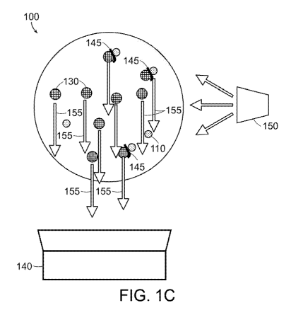
[0058] As shown in FIGS. 1A-1C, a bead-based assay system 100 for
detecting a complex including an analyte, shown in FIG. 1C, includes, as shown
in
FIG. 1A, a plurality of functionalized beads 110 of a first type (bead A),
which are
magnetic functionalized beads and are functionalized to include a first moiety
X
115 that associates with an analyte 120 under suitable conditions, a plurality
of
functionalized beads 130 of a second type (bead B), which are fluorescent
functionalized beads, and are functionalized to include an unlabeled moiety Y
135
that associates with the analyte 120 under suitable conditions, and, as shown
in
FIG. 1C, an optical photodetector 140 that detects light 155 emitted by the
functionalized beads 130 of the second type associated with the analyte 120 in
a
complex 145, shown in FIG. 1B, including the first type of functionalized bead
110,
the analyte 120, and the second type of functionalized bead 130. As shown in
FIG.
1C, the optical photodetector 140 is a spectrophotometer 140 that detects
fluorescence 155 emitted by the functionalized beads 130 of the second type
that
fluoresce when illuminated by light from a filtered lamp 150. Each of the
first 115
and second 135 moiety can be a receptor, protein, antibody, cell (eukaryotic
or
prokaryotic), organelle, virus, or nucleic acid sequence. The second moiety
135 is
unlabeled, that is, not labeled with a fluorophore. In some embodiments, the
fluorescent functionalized beads can comprise a polymer substrate impregnated
with a fluorescent material. Several improvements arise from having the
fluorescent material impregnated inside the functionalized beads B and using
an
unlabeled second moiety 135. First, the volume of the bead allows for much
greater quantities of fluorophores to be included and measured, as compared to
surface attachment, because the volume of the bead is significantly greater
than its
surface area. Second, in other methods whereby the surface bound moiety is
labeled with a fluorophore, the quantity of fluorophore is further reduced as
the
moieties do not cover the entire surface, resulting in even further reduced
labeling.
Third, fluorophores are sensitive to light, temperature, pH, salt and other
environmental conditions associated with biological assays. As such, the
fluorophores impregnated into the bead are sheltered and protected from the
CA 03046849 2019-06-11
=
WO 2018/119367 PC1/US2017/068126
chemical environment, which results in brighter and more robust detection.
Fourth,
for fluorophores to be conjugated or covalently bound to surface attached
moieties,
they must undergo a chemical reaction that can alter the state of the
fluorophore
(such as its 3D structure, charge, polarity) that can negatively affect the
function of
the fluorophore.
[0069] Due to the superparamagnetic nature of the capture bead A, extra
bead A will be included in the final read. However, since this bead is in a
different
fluorescent channel (wavelength) or not fluorescent at all, it will not
negatively
affect the positive signal of the detector bead B or provide additional non-
specific
(fluorescent) background.
[0060] In one embodiment, the magnetic multi-bead assay is performed as
described below. After complex formation, a magnetic separation step or series
of
repeated steps is used to reduce the unbound bead B population. After magnetic
separation, the continued presence of bead B indicates successful binding of
the
target analyte both to bead A and to bead B ¨ otherwise either the analyte or
bead
B or both would likely have been discarded during magnetic separation.
Detecting
bead B in the sample suspension is therefore sufficient to establish co-
presence of
both beads in complexes.
[0061] Accordingly, as shown in FIG. 2, a method 200 of detecting a complex
including an analyte includes contacting 210 a sample in a solution with a
population of magnetic functionalized beads of a first type, contacting 220
the
sample solution with a population of fluorescent functionalized beads of a
second
type, illuminating 230 the complex with incident light that excites
fluorescence
within the functionalized beads of the second type, and detecting 240 the
complex
including the analyte by analyzing the fluorescence.
[0062] The sample suspension may be analyzed using a fluorescent plate
reader or similar device that uses a spectrophotometer to optically excite and
measure fluorescence from each plate well. The suspension may be transferred
to
low-fluorescence black plates prior to measurement to reduce signal background
produced by the plate. While it is possible that the reactions could be
performed in
the black plates originally, reactions may be more efficiently performed in
round-
bottom plates that may be unavailable in black plastic. During the
fluorescence
16
CA 03046849 2019-06-11
=
WO 2018/119367 PCT/1JS2017/068126
, measurement, bead B fluorescence may be both induced and recorded through
optical band pass filters. A titration of bead B and a well containing no bead
B may
be separately measured to calibrate the observed fluorescence signal to a
known
bead concentration under similar buffer conditions.
[0063] Most commercially availablO fluorescent plate readers can be
configured with standard excitation and emission filters, dichroic or band
pass
filters, and proper gain settings or photo multiplier tube (PMT) adjustments
to
satisfactorily depress autofluorescence of sample buffer and amplify true
fluorescent signal from the ensemble fluorescent beads. The wavelength of
measured fluorescence will depend upon the choice of fluorophore incorporated
into the bead. It should be noted that low fluorophore concentration or weak
fluorophores may depress the fluorescent signal and reduce the sensitivity of
the
assay.
[0064] As shown in FIG. 1D, prostate specific antigen (PSA) as low as 0.1
pg/mL can be measured with little optimization of the plate reader conditions.
As
few as 250 fluorescent beads can be measured at the minimum signal level,
considered to be the fluorescence measurement background mean plus triple its
standard deviation. Longer read times, changes in photomultiplier tube (PMT)
gain
settings, or adjustments in the scanned region of each well all may contribute
to
improved sensitivity. Optimization of these parameters depends upon the
features
of any given plate reader.
Example 82: Magnetic-fluorescent assay with fluorescence imaging
[0065] Consider bead A and bead B to be of the same types described in
Example Al above. Further consider that, as in Example Al, a final magnetic
separation step or series of steps is performed to reduce the concentration of
bead
B.
[0066] In another embodiment employing a bead-based assay system 300,
shown in FIG. 3A, bead B fluorescence may be measured by fluorescence imaging
rather than with a spectrophotometer. The sample suspension or a portion of it
may be dispersed on a microscope slide 305. Under appropriate optical
excitation,
bead B fluorescence may be imaged by a microscopy system onto a camera
sensor 340 through an optical band pass filter 348 that blocks the excitation
light
17
CA 03046849 2019-06-11
WO 2018/119367 PCT/US2017/068126
from the filtered lamp 150. In the resulting bead B fluorescence image, and
provided suitable resolution of the microscopy system, individual beads may be
resolved, identified, and counted (as illustrated in FIG. 38). The total
number of
beads B counted in the image provides a measurement of the number of analytes
present in the sample, since the observation of bead B fluorescence 155
implies
co-presence of both bead A and bead B bound to the target analyte in the
complex
145.
[0067] Fluorescence imaging may provide an improvement in sensitivity
above the plate reader measurement described above in Example Al. This
improvement arises from the ability to reject confounding signals, including:
(1) optical detector backgrounds, such as arise from optical filter leakage
and
optical sensor noise;
(2) diffuse fluorescence backgrounds, such as autofluorescence from buffer
components;
(3) fluorescence from contaminants, such as dust particles, that may be
clearly
distinguished in images from bead B signals.
[0068] Rejecting false signals allows for a lower signal background, as shown
in FIG. 3C, where the imager 340 yields a lower signal level for the same PSA
concentration as compared to the plate reader 140, and a correspondingly
improved sensitivity to low complex concentrations that result from low
analyte
concentrations.
[0069] Imaging of bead B may be performed with a liquid sample suspension,
such as a droplet on a microscope slide under a coverslip, or after drying a
representative droplet of the liquid sample. After drying, fluorescent bead B
remains bright and no longer moves under diffusion or due to flow of the
sample on
the slide, which enables longer exposure times and lower excitation light
intensity.
The buffer solution is chosen to preserve immunocomplexes against dissociation
during drying, to disperse beads relatively uniformly over the dried region,
and to
avoid leaving solute crystals or other residue that may impede imaging.
18
CA 03046849 2019-06-11
WO 2018/119367 PCT/US2017/068126
Example C3: Magnetic-fluorescent assay with magnetic and fluorescence imaging
[0070] Consider bead A and bead B to be of the same types described in
Example Al above. Further consider that, as in Example Al, a final magnetic
separation step or series of steps is performed to reduce the concentration of
bead
B and that bead B is counted by imaging the sample with a fluorescence
microscopy system.
[0071] In accordance with one or more embodiments, as shown in FIG. 4, a
method 400 of detecting a complex including an analyte includes contacting 410
a
sample in a solution with a population of magnetic functionalized beads of a
first
type, contacting 420 the sample solution with a population of functionalized
beads
of a second type, and detecting 430 the complex including the analyte by
detecting
magnetic fields produced by the magnetic functionalized bead and by detecting
the
functionalized bead of the second type associated with the analyte in the
complex.
In some embodiments, detecting magnetic fields includes using any magnetic
imaging technology, such as magnetic force microscopy or a scanning Hall
probe.
In certain embodiments, detecting the functionalized beads of the second type
includes detecting fluorescence as described in Examples Al or B2 above.
[0072] In another embodiment, the microscopy system may include a wide-
field diamond magnetic imaging system that allows for imaging of bead A, which
is
superparamagnetic. Wide-field diamond magnetic imaging with nitrogen-vacancy
(NV) centers in diamond is capable of rapidly imaging magnetic fields disposed
over the surface of a diamond sensor, at room temperature, with sub-micron
resolution. Magnetic images may be co-registered to conventional optical
fluorescence or bright-field images acquired for the same field of view with
the
same imaging system. Adjustments to the imaging system may be made between
magnetic and optical imaging to optimize performance, such as changing optical
filters or correcting focal position.
[0073] As shown in FIG. 5, a bead-based magnetic assay system 500 for
detecting a complex including an analyte based on optically detected magnetic
resonance (ODMR) includes, as shown in FIG, IA and described above, a
plurality
of functionalized beads 110 of a first type, which are magnetic functionalized
beads
and are functionalized to include a first moiety 115 that associates with an
analyte
19
CA 03046849 2019-06-11
WO 2018/119367 PCT/US2017/068126
120 under suitable conditions, a plurality of functionalized beads 130 of a
second
type, which are functionalized to include a second moiety 135 that associates
with
the analyte 120 under suitable conditions, and, as shown in FIG. 5, a
substrate 532
including at least one ODMR center 540 (a plurality of ODMR centers 540 shown
in
FIG. 5), a light source 536 configured to generate incident light that excites
electrons within the at least one ODMR center 540 from a ground state to an
excited state, a magnet 534 for applying a bias magnetic field on a complex
530
disposed over the at least one ODMR center 540, the complex 530 including one
of
the first type of functionalized bead 110, the analyte 120, and one of the
second
type of functionalized bead 130, and a microwave source 538 configured to
generate a microwave field incident on the at least one ODMR center 540, the
microwave source 538 being further configured to generate the microwave field
with frequencies that correspond to ground state transitions in the at least
one
ODMR center 540, in which the at least one ODMR center 540 produces emitted
light 542 when illuminated by the incident light 536, characteristics of the
emitted
light 542 being influenced by the microwave field and by the magnetic
functionalized bead 110 associated with the analyte 120 in the complex 330. In
the
embodiment shown in FIG. 5, the plurality of ODMR centers 540 are nitrogen-
vacancy (NV) centers in a diamond lattice, formed in an upper surface of the
diamond substrate 532. In another aspect, the plurality of ODMR centers can be
silicon-vacancy centers in a silicon carbide lattice, or in a diamond lattice.
Turning
back to FIG. 5, under optical excitation 536, fluorescence 542 emitted from a
thin
layer of ODMR centers 540 near the surface of the diamond substrate 532 is
imaged onto an optical photodetector array 644, that is an optical imaging
system
having an imaging sensor such as a charge-coupled device (CCD) or
complementary metal oxide semiconductor (CMOS) camera. The variation of
ODMR center fluorescence under microwave excitation reveals the ODMR electron
spin resonance (ESR) frequency, and hence the magnetic field shift of the ODMR
spin sublevels. The spatial structure of the magnetic field at the diamond
surface
created by the sample (i.e., complex) 530 can thus be determined from images
of
ODMR center fluorescence 542, whose characteristics are influenced by the
microwave field and by the magnetic field created by the magnetic
functionalized
bead 110 associated with the analyte 120 in the complex 530.
CA 03046849 2019-06-11
1
WO 2018/119367 PCT/US2017/068126
[0074] Briefly, the process to acquire a magnetic image is as follows:
1. Dispose a magnetic sample (i.e., complex) 530 to be imaged
over, onto, or near to the sensing surface of the diamond substrate 532. An
intermediate layer (not shown) may be interposed between the sample 530
and the diamond substrate 532,
2. Apply a magnetic bias field 534 in an arbitrary direction.
3. Illuminate the ODMR centers 540 in the diamond center with
green light 536 (near 532 nm wavelength).
4. Apply a microwave field from a source 538 to the diamond,
with frequency near one of the ODMR center ESR transitions.
5. Acquire an image of ODMR center fluorescence 542 emitted
from the sensing surface 540 at optical detector array 544 through imaging
objective 546 and optical filter 548.
6. Repeat steps 4-5 using different microwave frequencies that
span one or more ranges around one or more NV center ESR transitions.
The result is a stack of images, each corresponding to a different microwave
frequency.
7. Repeat steps 4-6 one or more times, averaging the results to
reduce imaging noise in the image stack.
8. For each image pixel in the image stack, construct an ESR
spectrum from that pixel's value across all images in the stack. Analyze this
spectrum to determine the frequencies of one or more ESR transitions.
9. For each image pixel in the image stack, compute the
magnetic field based on the frequencies of observed ESR transitions
at that pixel.
[0075] Additional details of the operation of the wide-field diamond magnetic
imaging apparatus are described in PCT Patent Application No.
PCT/US2017/057628 filed on October 20, 2017 and entitled METHODS AND
APPARATUS FOR MAGNETIC PARTICLE ANALYSIS USING DIAMOND
MAGNETIC IMAGING that is incorporated by reference herein.
[0076] An applied magnetic field induces magnetization in bead A and an
associated magnetic field from the bead. A magnetic field in the range of 0.5
to 10
mT, which may be generated with permanent magnets or an electromagnet, is
21
CA 03046849 2019-06-11
WO 2018/119367 PCT/1JS2017/068126
sufficient to resolve features in the electron spin resonance spectrum of the
diamond imaging sensor. The diamond magnetic imager images these bead fields
directly, allowing for individual bead detection and location. Beads of
similar
composition and magnetization produce similar magnetic field patterns that may
be
identified as characteristic features 542 in a magnetic image corresponding to
the
location of each bead A. A representative image is shown in FIG. 6C.
[0077] An image processing algorithm may identify the locations both of bead
A features 542 in the magnetic image, shown in FIG. 6C, and bead B features
155
in the fluorescence image shown in FIG. 6B. Additional images may be acquired
in
either detection channel (magnetic or fluorescent) to improve signal fidelity.
The
resulting bead locations identified in each detection channel may then be
compared to identify co-presence of both bead types, and hence of complexes
145
containing the target analyte, illustrated in FIG. 6A.
[0078] Adding the magnetic imaging channel to detect bead A in addition to
detecting bead B in the bead fluorescence channel allows for identification of
unbound bead B, which may persist after magnetic separation or which may
dissociate from bead complexes that are weakly bound by nonspecific
interactions.
Unbound bead B may be rejected during analysis so that only bead B associated
with complexes are counted.
Example 04: Fully magnetic assay with magnetic imaging
[0079] In another embodiment shown in FIGS. 7A-70, bead A 710 and bead
B 730 are both magnetic, but with distinguishable magnetic properties.
Magnetic
imaging with single-bead spatial resolution is used to identify bead A 710, as
in
Example C3, and also to identify bead B 730, distinguishing between the two.
Bead A 710 has magnetic properties suitable for magnetic separation, as in
Examples Al, B2, and C3 described above.
[0080] Beads A 710 and B 730 may, for example, differ in the shape and
magnitude of their single-axis magnetization curves, which describe bead
magnetization as a function of an applied magnetizing field. Beads A 710 and B
730 may differ in the degree of hysteresis in their magnetization curves and
in
properties such as remanent magnetization and coercivity. Beads A 710 and B
730 may have different degrees of asymmetry, with different magnetization
curves
22
CA 03046849 2019-06-11
WO 2018/119367 PCT/US2017/068126
observed when the field axis is changed. Beads A 710 and B 730 may respond
differently to a time-varying magnetic field, such as an alternating or
rotating field.
[0081] Using only magnetic imaging for identifying and locating bead A 710,
bead B 730, and complexes 745 including the analyte 720 enables elimination of
the optical fluorescence detection channel, simplifying the assay system
significantly. Additionally, magnetic imaging is particularly insensitive to
signal
backgrounds due to unwanted light, detector noise, and sample contaminants
that
fluoresce, scatter, or absorb light. Magnetic signal backgrounds are extremely
low
in biological samples and they do not impede the ability to measure even
modestly
magnetic beads.
Distinguishing Magnetic Bead Types with Magnetic Imaging
[0082] Wide-field diamond magnetic imaging provides a means to directly
image the vector magnetic field produced by a magnetic bead under a wide range
of magnetic conditions. This general-purpose tool may be used to distinguish
between magnetic bead types over a wide range of different properties.
[0083] In one embodiment, bead A 710 and bead B 730 are distinguished by
measuring magnetic susceptibility and magnetic remanence at low applied field
after first magnetizing the beads with a large magnetic field. Bead A 710 is
superparamagnetic. For example, bead A 710 may be composed of
superparamagnetic iron oxide nanoparticles 5-10 nm in size dispersed within a
spherical polymer substrate approximately 1 pm in diameter. Bead A 710 may
contain a quantity of iron oxide such that the magnitude of the average
induced
magnetization of bead A 710 with an applied bias field of 4 mT is
approximately 3 x
10-15 A m2. Bead B 730 is ferromagnetic. In one embodiment, bead B 730 may be
composed of ferromagnetic cobalt ferrite nanoparticles 30 nm in size dispersed
over the surface of a spherical polymer substrate approximately 1 pm in
diameter
and adhered to the surface with an additional polymer layer. Bead B 730 has a
remanent magnetization fraction of greater than 50%, such that, after being
magnetized in a field of at least 300 mT and once the magnetizing field has
been
removed, bead B 730 retains a large proportion of its saturated magnetization
value. Bead B 730 may contain a quantity of cobalt ferrite such that the
magnitude
23
CA 03046849 2019-06-11
WO 2018/119367 PCT/US2017/068126
of the average remanent magnetization of bead B 730 after the magnetizing
field is
removed is approximately 2 x 10-15A m2.
[0084] A magnetic imaging procedure is described below for identifying
complexes 745 containing the target analyte 720, bead A 710 and bead B 730.
[0085] After forming complexes 745 in a sample suspension, a representative
portion of the sample is disposed over and dried on the surface 732, shown in
FIG.
7B, of a diamond magnetic imaging sensor shown in FIG. 5. The sensor's imaging
surface is a {100} face and this surface contains a thin layer approximately 1-
pm
thick that is rich in nitrogen-vacancy (NV) centers. Turning back to FIGS. 76-
7D,
after magnetic imaging, complexes 745 are identified by identifying bead A 710
and
bead B 730 in close proximity to one another, including close enough to be
spatially unresolved in the images. Prior to magnetic imaging, a magnetizing
field
is applied in a direction normal to the horizontal diamond surface. A field of
greater
than 200 mT applied for a period of several seconds is sufficient to magnetize
the
magnetic material in bead B. The dried sample is then magnetically imaged
twice
with a bias magnetic field of 4 mT applied parallel to one crystal axis of the
diamond sensor, which is oriented at an angle of approximately 35 degrees with
respect to the imaging surface. The 4 mT imaging field is reversed between
acquiring the two magnetic images, shown in FIGS. 7C and 70, termed the
positive
(FIG. 7C) and negative (FIG. 7D) images, denoting the +4 mT and -4 mT imaging
fields, respectively. The magnetic images measure the projection of the sample
magnetic field vector onto the axis of the imaging field.
[0086] Since bead A 710 is superparamagnetic, the greater than 200 mT
magnetizing field does not leave bead A 710 with significant remanent
magnetization. In both the positive and negative images, the magnetization of
bead A is only that which is induced in the superparamagnetic beads by the 4
mT
imaging field. Bead A 710 produces the same feature 741 in both magnetic
images, since the bead A 710 magnetization is in both cases parallel to the
imaging field.
[0087] In contrast, the greater than 200 mT magnetizing field leaves bead B
730 strongly magnetized in the vertical direction, oriented up with respect to
the
horizontal diamond sensor imaging surface. Once the magnetizing field is
24
CA 03046849 2019-06-11
WO 2018/119367 PCT/1152017/068126
removed, the weaker 4 mT imaging field does not significantly change the
magnetization of bead B 730, since the magnetic susceptibility of bead B 730
near
zero magnetic field, when previously magnetized along the same axis, is low.
Therefore, bead B 730 produces an image feature 742 that inverts sign between
the positive and negative magnetic images, with positive magnetic field
projection
changing to negative and vice versa, as illustrated in FIGS. 7B, 7C, and 7D.
[0088] All magnetic objects identified in the magnetic image field of view are
quantified by magnetization, such that bead A 710 is assigned a positive value
in
both images and bead B 730 is assigned a positive and negative value in the
positive and negative images, respectively. Bead complexes 745 will be
assigned
magnetization values that reflect the complex composition. For example, bead
dimers of the form A-A or B-B will generally be assigned larger values with
the
same sign of bead A or bead B monomers, respectively. Bead dimers 745 of the
form A-B or larger heterogeneous bead complexes will be assigned values of
smaller magnitude in the negative image than in the positive image, reflecting
oppositely-magnetized beads within the complex, as shown in FIGS. 7C and 7D.
[0089] All magnetic objects in the magnetic images may be represented on a
scatter plot whose axes are the sum and difference, respectively, of the
positive
and negative image magnetization values. This sum and difference may also be
termed the susceptibility and remanence of the single-bead magnetization
curve,
as they are approximately proportional to these properties. As shown in FIG.
8A,
bead A and bead complexes containing only bead A will be clustered near one
axis, with large susceptibility and zero remanence; bead B and bead complexes
containing only bead B will be clustered near the other axis, with large
remanence
and near-zero susceptibility. Complexes containing both bead A and bead B will
exhibit significant susceptibility and remanence, so they may be identified as
the
objects in the scatter plot in a region sufficiently separated from both axes.
This
region is unlikely to contain signals from bead A or bead B alone, or from
homogeneous bead complexes such as those of the form A-A or B-B.
[0090] If the magnetic imaging spatial resolution is sufficient to resolve
individual magnetic beads within a complex, then the complex may be identified
by
separately identifying beads within the complex and determining their spatial
CA 03046849 2019-06-11
WO 2018/119367 PC11US2017/068126
separation to be consistent with that of a bound complex, and not
significantly
greater than the bead diameters.
[0091] If both bead A and bead B are sufficiently magnetic, and either bead A
or bead B is ferromagnetic, A-B dimers may form even in the absence of the
target
analyte, due to attractive magnetic interactions. These magnetic interactions
may
be limited in strength by limiting the amount of magnetic material in each
bead.
Magnetic bead signals may be measured even in cases in which magnetic
interactions between beads are too weak to overcome forces associated with
Brownian motion or sample mixing, so that magnetic interactions may play no
role.
[0092] The magnetic material within bead A and bead B may be composed of
nanoparticles disposed within or on the surface of a polymer or other
nonmagnetic
substrate. If the nanoparticles are uniformly disposed within or on the
surface of
the substrate, then the strength of magnetic interactions between beads can be
reduced relative to having aggregated nanoparticles, since magnetic fields
near
aggregated magnetic nanoparticles may be stronger. Using nanoparticles that
are
much smaller than the substrate radius may allow for more uniform
distribution,
relative to larger nanoparticles that produce stronger local magnetic fields.
[0093] Magnetic interactions may also be suppressed by adding a
nonmagnetic layer encapsulating the magnetic material. Suitable materials for
the
nonmagnetic layer include polymers, such as polyethylene (PE),
polytetrafluoroethylene (PIE E), and polymethylmethacryiate (PMMA). Since
magnetic interactions weaken rapidly with increasing separation between beads,
even a nonmagnetic layer significantly thinner than the original bead radius
can
dramatically reduce dimer formation due to magnetic interactions.
Additional Maonetic Discrimination Methods
Discrimination by magnetic moment
[0094] As shown in FIG. 8B, the magnetic image signal for a magnetic bead
can be analyzed to determine the magnetic moment (magnetization x volume) of
the bead, assuming knowledge of the bead size and a spherically symmetric
distribution of magnetic material in the bead. For bead A and bead B of
similar
size, the magnetic moment can be used to distinguish between bead A, bead B,
26
CA 03046849 2019-06-11
WO 2018/119367 PCT/US2017/068126
and bead complexes, To be effective, there must be low enough variation of
magnetic moment, size, and spherical symmetry of each bead such that each
measurement can be clearly associated with one distribution. The A-B complex,
having larger size than each individual bead, may not produce a signal equal
to the
sum of signals from bead A and bead B. Nevertheless, the bead A and bead B
magnetic moments may still be chosen such that the mean A-B complex signal is
distinct from that of bead A, bead B, the A-A complex, the B-B complex, etc.
It is
not necessary to resolve spatial differences between candidate signals to
discriminate them by magnetic moment; it is sufficient to evaluate each signal
only
by magnitude, e.g. magnitude of convolution with a characteristic image
signal.
[0096] If bead A and B have different size, a similar discrimination approach
may be used that ignores this size difference when evaluating the magnitude of
candidate signals and applies the same single-parameter quantification
strategy to
all signals. This may produce signals for bead A, bead B and complexes that
are
not proportional to their magnetic moments, but are distinct and allow for
accurate
discrimination.
Discrimination by anisotropy
[0096] Magnetic particles may exhibit an anisotropic response to a magnetic
field, due to preferential magnetization along certain crystal axes in a
single
magnetic domain or along certain directions in a multi-domain particle or a
composite magnetic bead containing many particles. Rod-shaped nanoparticles,
for example, typically can be magnetized more easily along the rod axis.
Synthesizing a spherical bead containing oriented magnetic nanorods would
produce an anisotropic magnetic susceptibility in the bead.
[0097] The magnetic anisotropy of a bead can be probed by imaging
immobilized beads multiple times, using multiple directions of an applied
magnetic
field. As shown in FIG. 8C, a metric for magnetic anisotropy can be
constructed
from the difference in magnetic signals obtained from the different
orientations.
Imaging at three distinct directions is sufficient to determine the
orientation and
degree of anisotropy for a particle even if the particle orientation is not
known in
advance. If bead A and bead B have zero and nonzero magnetic anisotropy,
respectively, then images acquired with the imaging magnetic field rotated in
27
CA 03046849 2019-06-11
WO 2018/119367 PCTIUS2017/068126
different directions will produce identical signals for bead A, but different
signals for
bead B. Complex signals will have nonzero anisotropy, but less than that of
bead
B.
Discrimination by coercivity
[0098] As shown in FIG. 8D, magnetized ferromagnetic beads can be re-
magnetized in a different direction by applying a field larger than the
coercivity.
Discrimination between two types of ferromagnetic beads, bead A and bead B,
can
be achieved using this sequence: (1) first magnetize both beads with a strong
magnetic field in one direction; (2) image the bead magnetization; (3) apply a
magnetic field in the opposite direction that is strong enough to reverse the
magnetization of bead A, but not strong enough to reverse the magnetization of
bead B; (4) image the magnetic bead signals and compare them to those in the
first image. Bead A signals will reverse direction; bead B signals will change
modestly, if at all; complex signals will change significantly in magnitude as
one
bead in the complex reverses magnetization while the other does not.
Discrimination by time-dependent magnetic response
[0099] As shown in FIG. 8E, magnetic particles change their magnetization
direction in response to a change in magnetic field direction. For a given
field
strength, the time scale for a particle to change direction may depend on the
particle composition and size and may vary over a wide range from below 1 ps
to
well over 1 s. If an oscillating or rotating AC magnetic field of constant
amplitude is
applied to the particle, the particle magnetization will oscillate in
response. An
oscillating magnetization may be measured by a magnetic imaging technology
that
is sensitive to AC magnetic fields, such as a wide-field ODMR center magnetic
imaging system that employs pulsed optical excitation of ODMR centers or time-
gated camera exposures. The magnitude of the oscillating magnetization will
decrease as the oscillation period decreases below the time scale required for
the
particle to change magnetization direction. The cutoff frequency is defined as
the
oscillation frequency corresponding to this change in response.
[00100] If bead A and bead B contain magnetic material with different cutoff
frequencies, measuring the oscillating magnetization at multiple oscillation
frequencies provides a method to discriminate between the beads. If bead A has
a
28
CA 03046849 2019-06-11
WO 2018/119367 PCT/US2017/068126
high cutoff frequency compared to bead B, then imaging at an intermediate
frequency will observe a weak bead B signal compared to imaging at a low
frequency, but little change in the bead A signal. A complex will exhibit a
decrease
in signal at the intermediate frequency that is smaller than that of bead B.
Discrimination can be improved by adding additional images at additional
frequencies. While bead A and bead B will have a single cutoff frequency, the
complex will exhibit two cutoff frequencies. Signals obtained at low
oscillation
frequency and at two or more intermediate frequencies will reveal
qualitatively
different behavior for bead A, bead B, and complexes.
Discrimination by Magnetic saturation
[00101] As shown in FIG. 8F, the magnetization M of a superparamagnetic
particle saturates with sufficiently high magnetic field H. Even at field
strengths
below saturation, the magnetic susceptibility (slope of the magnetization
curve) is
reduced. If the magnetizations of superparamagnetic bead A and bead B saturate
at different field strengths Hi and H2, then the beads may be distinguished by
imaging at two magnetic field strengths, one of which is large enough to
observe a
change in magnetic susceptibility in one of the beads. The ratio of signals in
these
two images will be significantly different for bead A and bead B. Complexes
will
have an intermediate ratio distinct from that of bead A or bead B.
Size based magnetic bead discrimination
[00102] Magnetic beads of different size, but similar composition, may produce
magnetic image signals that are distinguishable by their spatial scale. This
may
allow for discrimination between bead.A, bead B, and complexes, despite bead A
and bead B having nominally identical magnetic properties.
[00103] When the sample solution is disposed on a surface, most beads will
come to rest against the surface, so that the center of each bead is spaced
from
the surface by its radius. Larger beads are thus centered further from the
sensing
surface than smaller beads. This spacing determines the spatial scale of the
magnetic field at the sensing surface, since the same lateral displacements
along
the surface are relatively larger for closely-spaced beads than for more
distant
beads, and therefore result in larger relative changes in magnetic field.
29
CA 03046849 2019-06-11
WO 2018/119367 PCT/US2017/068126
[00104] FIG. 9 is an image of two beads, approximately 1 micron (top) and 3
microns (bottom) in diameter, with their centers spaced approximately 9
microns
apart. The larger bead produces a magnetic signal with broader spatial
features.
In this case, the larger bead also contains more magnetic material and
produces a
larger magnitude of signal, but this need not be the case.
[00105] If bead A and bead B have different size, but similar magnetic
properties, then spatial scale of magnetic image signals may be used not only
to
discriminate between the two, but also to identify A-B complexes. Complexes
have
spatially broad signals that also contain shorter-scale spatial components.
[00106] One method for identifying complexes is to first identify all broad
signals (including both bead B and complex signals) and then subtract a
characteristic bead B signal (such as the mean of many bead B signals imaged
separately) from each. Variations in imaging accuracy and in the uniformity of
bead B magnetization will cause this difference to be nonzero for bead B
signals,
however the difference will generally have broad spatial scale. For the
complex
signals, however, subtracting the characteristic bead B signal will leave
behind the
sharper bead A signal. These cases may be distinguished by spatial filtering
of the
signal differences.
[00107] FIGS. 10A-1, 10B-1, and 10C-1 show example bead B images. The
difference signal images after subtracting the characteristic bead B signal
shown in
10A-2, 10B-2, and 10C-2 have a gray scale amplified by a factor of 2.
[00108] FIGS. 11A-1, 11B-1, and 11C-1 show example complex images,
showing sharp bead A signals circled in the difference images shown in 11A-2,
11B-2, and 11C-2, which are again amplified by a factor of 2 relative to the
image
signals.
Corn bined approaches
[00109] The bead discrimination approaches described herein may also be
used in combination to enhance discrimination performance or to discriminate
between more than two bead types and their combinations.
CA 03046849 2019-06-11
WO 2018/119367 PCT/US2017/068126
Additional Assay Features
Accounting for variation in bead density
[00110] For a given number of bead complexes containing the target
analyte in a liquid sample suspension, the number of complexes present within
an imaging field of view after disposing the sample over the imaging sensor
may
vary due to differences in the manner in which the sample was disposed. For
example, the sample may be disposed over the sensor by adding a liquid droplet
to the sensor surface and allowing it to dry, such that variations in the
droplet
volume or its initial contact area with the sensor lead to variations in bead
complex density in the dried sample over the sensor surface. By measuring the
total number of bead A in the field of view, including the unbound beads not
contained in complexes, the sample density variations may be measured and
accounted for. Dividing the number of complexes by the number of bead A
yields a quantity that is less sensitive to variations in sample density, and
thus
may provide a more precise measurement of the total number of bead
complexes in the sample and of the analyte concentration determined from a
calibration curve obtained as described above.
Accelerated bead interaction kinetics
[00111] It is known in the art that immunoassays must allow time for
target analytes in a liquid sample to bind to antibodies that enable detection
of
the target analytes. Depending on the reagent concentration and sample
conditions (such as temperature, viscosity, and process for agitating or
mixing
the sample), several minutes may be required for most analytes to become
bound, even when there is a large excess of binding sites available, due to
the
time needed for the analyte to move through the sample by diffusion or active
shaking or stirring.
[00112] The rate of interactions between different beads in the
sample
suspension may determine multi-bead assay speed, since bead diffusion is
generally slower than diffusion of smaller molecular analytes. Since a bead-
bound target analyte may also occupy a relatively small fraction of the bead's
surface area, when the bead to which the analyte is bound interacts with a
second bead, the analyte may not be exposed to the second bead in a manner
31
CA 03046849 2019-06-11
WO 2018/119367 PCT/US2017/068126
conducive for binding (e.g., the interaction occurs on the side of the first
bead
opposite to where the analyte is located). Several bead interactions may be
required on average to form an immunocomplex. The multi-bead assay time
may be shortened by performing processes to induce bead-bead interactions
that lead to immunocomplex formation, accelerating bead kinetics beyond what
may be expected for diffusion or stirring alone.
[00113] In one embodiment, bead-bead interactions may be induced
by agglomerating a plurality of functionalized beads of the first and second
types, after contacting the sample solution with the population of
functionalized
beads of the second type, before detecting the complex, by means of spinning
the sample suspension on a centrifuge to concentrate the beads into a pellet
in
the sample tube. This process can be performed in less than a minute with
standard benchtop centrifuge systems. Beads in the pellet may be closely
spaced or in contact with one another, resulting in many bead interactions in
the
pellet. The pellet may be re-suspended by mixing the suspension. This
centrifuge process may be repeated as necessary to ensure sufficient
interactions between beads to form immunocomplexes containing the target
analyte.
[00114] In another embodiment, if both bead A and bead B are
magnetic, then magnetic separation may be used to form a pellet of beads in
the
sample suspension and induce bead-bead interactions by applying a magnetic
field gradient to the sample solution after contacting the sample solution
with the
functionalized beads of the first and second types. As with the centrifuge
process, this magnetic approach to accelerating bead kinetics can be performed
in less than a minute and repeated as necessary to form immunocomplexes
containing the target analyte. The magnetic approach may be performed with
permanent magnets for a simple, inexpensive, and compact process with
minimal power consumption. An electromagnet may also be used to apply the
magnetic field with no moving parts.
[00115] In another embodiment, a bead pellet produced by magnetic
separation of a sample suspension can be agitated without removing the
magnetic field, but by varying or otherwise changing the magnetic field
gradient
applied to the sample solution with respect to the beads. For example, the
field
32
CA 03046849 2019-06-11
WO 2018/119367 PCT/US2017/068126
magnitude, direction, or spatial distribution may be changed or oscillated to
apply different magnetic forces on the beads. Alternatively, or additionally,
the
sample tube may be moved with respect to the magnetic field. For example,
rotating the tube may move the pellet away from its equilibrium position so
that
the pellet will be dragged by the magnetic field gradient to a new position.
These changes will cause beads in the pellet to move with respect to each
other
and may induce additional bead interactions and immunocomplex formation.
[00116] In an embodiment, a permanent magnet may be moved
relative to a tube containing a sample suspension with magnetic beads of
multiple types. The magnet may follow a fixed pattern of motion. Exemplary
cases include the magnet orbiting the sample tube in a circle, rotating on its
own
axis, or rocking back and forth between two points. The motion may be
continuous, in which case the bead pellet will continuously move through the
tube, subjecting the beads to shear forces from the liquid, tube walls, and
other
beads. This motion and the associated forces on the beads will agitate the
pellet continuously to drive bead-bead interactions. In another exemplary
case,
the motion may occur in discrete periods separated by periods of rest, in
which
the bead pellet may concentrate to a higher bead density than is achieved
during continuous motion. If the different bead types respond significantly
differently to the field of the permanent magnet, then the periods of rest
will allow
the multiple bead types to co-localize more effectively than during continuous
motion.
[00117] In another embodiment, a plurality of permanent magnets may
be moved relative to a plurality of samples in separate wells of a plate, such
that
the sample in each well is subjected to a magnetic field profile in time and
space
that is substantially similar. This approach allows for driving bead-bead
interactions in parallel over a plurality of samples for improved sample
preparation throughput.
[00118] Accelerating bead kinetics and the rate of bead-bead
interactions in sample suspension decreases the time required to bind target
analytes into detectable multi-bead complexes. This method enables a rapid
assay.
33
CA 03046849 2019-06-11
WO 2018/119367 PCT/US2017/068126
[00119] This method may also allow for a lower quantity of binding
ligands to be used on the bead surfaces, since the likelihood of a given
ligand to
bind to the target analyte may be increased by the increased frequency of bead-
bead interactions. Using fewer binding ligands may reduce the cost of the
assay
significantly.
Multiplexing
[00120] It is often useful for an assay to measure concentration of
multiple distinct analytes in a single sample. A multiplexed assay measures
distinct target analytes by associating a distinct signal with each target, so
that
the analyte signals may be distinguished in the assay measurement. The
magnetic dual-bead assay may be generalized to a multiplexed multi-bead
assay by using more than two distinguishable bead types. Different analytes
may be specifically detected by observing the formation of analyte-specific
complexes including a plurality of functionalized beads of at least a third
type,
functionalized to include at least a third moiety that can specifically
associate
with at least a second analyte under appropriate conditions.
[00121] In one embodiment, shown in FIGS. 12A and 12B, consider a
plurality of functionalized beads of the third type 1240 functionalized to
include
at least a third moiety 1245 that associates with the second analyte 1250
under
suitable conditions, and a plurality of functionalized beads of a fourth type
1260,
functionalized to include a fourth moiety 1265 that associates with the second
analyte 1250 under suitable conditions, resulting in four distinguishable bead
types: bead A 1210, bead B 1230, bead C 1240, and bead D 1260. Complexes
of the form A-B 1201 or C-13 1202 may be formed through binding of two
distinct
analytes, first analyte X 1220 and second analyte Y 1250, to moieties coating
each bead. In this case, bead A 1210 and bead B 1230 are coated with
moieties 1215 and 1235, respectively, targeting two distinct regions X1 and X2
of analyte X 1220; bead C 1240 and bead D 1260 are coated with moieties 1245
and 1265, respectively, targeting two distinct regions Y1 and Y2 of analyte Y
1250. The moieties on each bead are unique to that bead. The A-B 1201 and
C-D 1202 complexes may be distinguished from each other and from the
monomer beads from their distinct magnetic properties.
34
CA 03046849 2019-06-11
WO 2018/119367 PCT/US2017/068126
[00122] In another embodiment, shown in FIGS. 13A and 13B,
consider three distinguishable bead types: bead A 1310, bead B 1320, and bead
C 1330. Complexes of the form A-8 1301, B-C 1302, or A-C 1303 may be
formed through binding of three distinct analytes, analyte X 1311, analyte Y
1312, and analyte Z 1313, to moieties coating each bead. The functionalized
beads of the first type A 1310 further include at least one additional moiety
1316
that associates with the second analyte 1312 under suitable conditions. The
functionalized beads of the second type B 1320 further include a moiety 1326
that associates with the third analyte Z 1313 under suitable conditions. The
functionalized beads of the third type C 1330 are functionalized to include a
moiety 1335 and a moiety 1336, and therefore each bead is coated with two
distinct moiety types targeting two different analytes: bead A 1310 is coated
with
moieties for analyte X 1315 and for analyte Y 1316; bead B 1320 is coated with
moieties for analyte X 1325 and for analyte Z 1326; bead C 1330 is coated with
moieties for analyte Y 1335 and for analyte Z 1336. The moieties on each bead
are unique to that bead. The A-B 1301, B-C 1302, and A-C 1303 complexes
may be distinguished from each other and from the monomer beads from their
distinct magnetic properties.
[00123] Multiplexed assays must have a means of discriminating
between signals associated with distinct target analytes, which in the case of
multiplexed bead assays means that the beads must be distinguishable. Bead
fluorescence may be used to discriminate between bead types with different
excitation and/or emission spectra. For example, three bead types may emit
blue, yellow, or red fluorescence that may be distinguished using optical
filters.
Different bead types may also be prepared to fluoresce with different
intensities,
so that the different types may be distinguished in a fluorescence image by
discrete levels of brightness, where difference between the levels exceeds
variation within the distribution of each bead type.
[00124] Distinct magnetic bead types may be distinguished by
preparing bead types with different magnetic properties that can be
distinguished by magnetic imaging. In an exemplary case, the distinct bead
types may be prepared by loading each bead type with specific and
distinguishable quantities of magnetic material. In another exemplary case,
CA 03046849 2019-06-11
WO 2018/119367 PCT/US2017/068126
distinct bead types may be prepared by loading each bead type with different
magnetic material exhibiting different properties. The fully magnetic multi-
bead
assay described above discriminates between two bead types in this manner. A
multiplexed assay may be implemented by adding additional distinguishable
beads using distinct combinations of the properties described above. For
example, bead A may be superparamagnetic, while bead B and C are
ferromagnetic with different coercivities derived from bead B and bead C
comprising different ferromagnetic materials. In this case, the beads may be
distinguished by measuring magnetic remanence after magnetization, and then
also measuring whether this remanence is reversed upon application of a
demagnetizing field that exceeds the coercivity of bead B, but not that of
bead
C. The three beads in this case may be used to implement a multiplexed assay
for three analytes using an embodiment described above.
Sample Preparation
[00125] One example of suitable conditions for sample preparation for
the multi-bead assay is to combine a few drops of blood with the multi-bead
mixture, incubate for a few minutes with accelerated kinetic mixing and
deposit
the sample solution on the diamond surface to dry followed by magnetic
imaging. The sample solution can be partially or completely dehydrated before
detecting the complex.
[00126] A suitable sample preparation proceeds as follows: plasma or
serum is diluted in assay buffer 10-fold by adding 5 pL sample into 45 pL
assay
buffer and briefly vortex mixed. This diluted sample is further diluted 2x
with 50
pL of bead mix for a final of 100 L. The bead mix includes -100,000 capture
beads and -100,000 detector beads. The final assay reaction is 20-fold
dilution
of sample in 100 pL. The assay reaction is incubated with vortex mixing (800
rpm) for 15 minutes at room temperature. The samples are then placed in a
centrifuge and spun at 1500 g for 3 minutes, followed by pulse vortex mixing.
The centrifugation and mixing cycle is repeated twice more, after which the
sample is placed against a permanent magnet (magnetic field -300 ml) for 30
seconds to pellet the magnetic beads against the sidewall of the reaction
tube.
The assay volume is removed by pipette leaving the bead pellet intact on the
36
CA 03046849 2019-06-11
WO 2018/119367 PCT/US2017/068126
side wall against the magnet. The tube is removed from the magnet and the
pellet is suspended in 500 pL of wash buffer by vortex mixing. The tube is
pulse
spun at 1500 g for 3 seconds to remove fluid from the cap, and placed on the
magnet for 30 seconds. The wash cycle is repeated 2 more times for a total of
3
washes. The pellet is washed 1 time with 200 pL of imaging buffer and finally
suspended in -4 pL imaging buffer. -2 pL is applied to the diamond sensor for
magnetic imaging.
[00127] The sample may be any chemical or biological sample, such
as whole blood, blood components (plasma, serum), tissue culture, cell
culture,
bodily fluids (cerebral spinal fluid (CS F), tears, saliva, breast milk,
urine, semen,
nasal discharge), tissue samples (oral swabs, biopsies, surgical resections),
recombinant DNA, RNA or protein, endogenous DNA, RNA or protein, synthetic
nucleic acids or protein peptides.
[00128] Further sample requirements may include volumes of sample
types from 0.1 pL to 1000 pL.
[00129] Further sample requirements may include dilution of sample
types and volume into assay buffers. Dilutions of sample types may include
dilution by a factor of 10-1,000. Assay buffers may be determined empirically
for
optimized signal generation and minimized non-specific background, or false
binding of any kind.
[00130] Samples may be combined in various ways including, for
example, with multi-bead mixtures in blood collection tubes, assay tubes,
assay
plates/well, microfluidic devices, reaction chambers, incubation chambers,
lateral flow devices, blood component separation devices, or other liquid
handling or manipulation devices.
[00131] Samples may be mixed in various ways including, for example,
by magnetic fields, centrifugal force, gravity, sound induced, light induced,
electric induced, ionic interactions, van der Waals induced, Brownian motion,
spinning, or other mechanical means.
[00132] Samples may be mixed with multi-bead mixtures for times
necessary to capture targets of interest ranging from, for example, a second
to
several hours.
37
CA 03046849 2019-06-11
WO 2018/119367 PCT/1JS2017/068126
[00133] Samples may be introduced to the magnetic imaging device in
various ways including, for example, by pipette, capillary flow tube or
device,
sample handling device, liquid handling device, integrated device, lateral
flow
device, disposable or reusable device.
[00134] Samples may be deposited on the diamond surface by several
modes of application including, for example, pipetting, pouring, dripping,
capillary flow, pumping, gravity induced flow, magnetic induced flow, ionic
induced flow, sound induced flow, light induced flow, mechanical vibration
induced flow, sheath flow, centrifuge induced, and thermal induced flow.
[00135] Samples may be magnetically imaged in a dry, dehydrated
(i.e., partially dry or gel), or wet state.
Further Example Embodiments
[00136] Example I is a bead-based magnetic assay system for
detecting a complex including an analyte based on optically detected magnetic
resonance (ODMR), the system comprising: (a) a plurality of functionalized
beads of a first type, which are magnetic functionalized beads and are
functionalized to include a first moiety that associates with an analyte under
suitable conditions, (b) a plurality of functionalized beads of a second type,
which are functionalized to include a second moiety that associates with the
analyte under suitable conditions, (c) a substrate including at least one ODMR
center, (d) a light source configured to generate incident light that excites
electrons within the at least one ODMR center from a ground state to an
excited
state, (e) a magnet for applying a bias magnetic field on a complex disposed
over the at least one ODMR center, the complex including one of the first type
of
functionalized bead, the analyte, and one of the second type of functionalized
bead, (f) a microwave source configured to generate a microwave field incident
on the at least one ODMR center, the microwave source being further
configured to generate the microwave field with frequencies that correspond to
ground state transitions in the at least one ODMR center, in which the at
least
one ODMR center produces emitted light when illuminated by the incident light,
characteristics of the emitted light being influenced by the microwave field
and
by the magnetic functionalized bead associated with the analyte in the
complex,
38
CA 03046849 2019-06-11
=
WO 2018/119367 PCT/US2017/068126
and an optical photodetector that detects light emitted by the at least one
ODMR center.
[00137] Example 2 includes the subject matter of Example 1, wherein
the at least one ODMR center is a silicon vacancy center in a silicon carbide
lattice,
[00138] Example 3 includes the subject matter of Example 1, wherein
the at least one ODMR center is a silicon vacancy center in a diamond lattice.
[00139] Example 4 includes the subject matter of Example 1, wherein
the at least one ODMR center is a nitrogen-vacancy center in a diamond
lattice.
[00140] Example 5 includes the subject matter of Example 4, wherein
the at least one ODMR center is formed in an upper surface of the substrate.
[00141] Example 6 includes the subject matter of Example 5, wherein
the at least one ODMR center is a plurality of ODMR centers formed in the
upper surface of the diamond substrate.
[00142] Example 7 includes the subject matter of Example 6, wherein
the optical photodetector is an optical imaging system having an imaging
sensor
that images the emitted light from the plurality of ODMR centers.
[00143] Example 8 includes the subject matter of any of Examples 1-7,
wherein each of the first and the second moiety is a receptor, protein,
antibody,
cell, virus, or nucleic acid sequence.
[00144] Example 9 includes the subject matter of any of Examples 1-8,
wherein the functionalized beads of the first type are superparamagnetic
functionalized beads including a superparamagnetic material.
[00145] Example 10 includes the subject matter of Example 9, wherein
the functionalized beads of the first type include a nonmagnetic layer
encapsulating the superparamagnetic material.
[00146] Example 11 includes the subject matter of Example 9, wherein
the superparamagnetic functionalized beads include iron oxide particles.
39
CA 03046849 2019-06-11
WO 2018/119367 PCT/US2017/068126
[00147] Example 12 includes the subject matter of any of Examples 1-
11, wherein the functionalized beads of the first type comprise magnetic
nanoparticles disposed within a polymer substrate.
[00148] Example 13 includes the subject matter of any of Examples I-
ll, wherein the functionalized beads of the first type comprise magnetic
nanoparticles disposed on a surface of a polymer substrate.
[00149] Example 14 includes the subject matter of any of Examples 1-
13, wherein the functionalized beads of the second type are fluorescent
functionalized beads.
[00150] Example 15 includes the subject matter of any of Examples 1-
13, wherein the functionalized beads of the second type are magnetic
functionalized beads including a quantity of magnetic material distinguishable
from the functionalized beads of the first type.
[00151] Example 16 includes the subject matter of any of Examples 1-
13, wherein the functionalized beads of the second type are magnetic
functionalized beads, the second type of functionalized beads including a
magnetic property distinguishable from the functionalized beads of the first
type.
[00152] Example 17 includes the subject matter of Example 16,
wherein the functionalized beads of the first type are superparamagnetic
functionalized beads including a superparamagnetic material.
[00153] Example 18 includes the subject matter of Example 17,
wherein the functionalized beads of the first type include a nonmagnetic layer
encapsulating the superparamagnetic material.
[00154] Example 19 includes the subject matter of Example 16,
wherein the functionalized beads of the second type are ferromagnetic
functionalized beads including a ferromagnetic material.
[00155] Example 20 includes the subject matter of Example 19,
wherein the functionalized beads of the second type include a nonmagnetic
layer encapsulating the ferromagnetic material.
CA 03046849 2019-06-11
WO 2018/119367 PCT/1JS2017/068126
[00156] Example 21 includes the subject matter of any of Examples 1-
20, wherein each of the first type of functionalized beads and the second type
of
functionalized beads has a diameter in a range of between 50 nm and 10 gm.
[00157] Example 22 includes the subject matter of Example 21,
wherein each of the diameters of the functionalized beads of the first type
and
the second type is in a range of between 0.5 gm and 5 gm.
[00158] Example 23 includes the subject matter of Example 21,
wherein the diameter of the functionalized beads of the first type is similar
to the
diameter of the functionalized beads of the second type.
[00159] Example 24 includes the subject matter of Example 21,
wherein the diameter of the functionalized beads of the first type is
different from
the diameter of the functionalized beads of the second type by at least 50%.
[00160] Example 25 includes the subject matter of any of Examples 1-
24, further including a plurality of functionalized beads of at least a third
type,
functionalized to include at least the second moiety that can specifically
associate with at least a second analyte under appropriate conditions.
[00161] Example 26 includes the subject matter of Example 25, further
including a plurality of functionalized beads of a fourth type, functionalized
to
include the second moiety that associates with the second analyte under
suitable conditions,
[00162] Example 2/ includes the subject matter of Example 25,
wherein the functionalized beads of the first and/or second type further
include
at least one additional moiety that associates with the second analyte under
suitable conditions.
[00163] Example 28 includes the subject matter of Example 27, further
including a third moiety that associates with a third analyte under suitable
conditions, wherein the functionalized beads of the first type are further
functionalized to include the second moiety, and the functionalized beads of
the
second type are further functionalized to include the third moiety.
[00164] Example 29 is a method of detecting a complex including an
analyte, the method comprising: (a) contacting a sample in a solution with a
41
CA 03046849 2019-06-11
=
WO 2018/119367 PCT/US2017/068126
population of functionalized beads of a first type, which are magnetic
functionalized beads and are functionalized to include a first moiety that
associates with an analyte under suitable conditions, (b) contacting the
sample
solution with a population of functionalized beads of a second type, which are
functionalized to include a second moiety that associates with the analyte
under
suitable conditions, contact resulting in formation of a complex including one
of
the first type of functionalized bead, the analyte, and one of the second type
of
functionalized bead; and (c) detecting the complex including the analyte by
detecting magnetic fields produced by the magnetic functionalized bead and by
detecting the functionalized bead of the second type associated with the
analyte
in the complex.
[00165] Example 30 includes the subject matter of Example 29, further
including disposing the sample solution including the complex over a substrate
that includes at least one optically detected magnetic resonance (ODMR) center
formed in the substrate; exciting electrons within the at least one ODMR
center
from a ground state to an excited state with incident light; applying a bias
magnetic field on the complex; and generating a microwave field incident on
the
at least one ODMR center, the microwave field including frequencies that
correspond to ground state transitions in the at least one ODMR center,
wherein
detecting the complex including the analyte further includes analyzing light
emitted by the at least one ODMR center, characteristics of the emitted light
being influenced by the microwave field and by the magnetic functionalized
bead
associated with the analyte in the complex.
[00166] Example 31 includes the subject matter of Example 30,
wherein the at least one ODMR center is a nitrogen-vacancy center in a
diamond lattice.
[00167] Example 32 includes the subject matter of Example 31,
wherein the at least one ODMR center is formed in an upper surface of the
substrate.
[00168] Example 33 includes the subject matter of Example 32,
wherein the at least one ODMR center is a plurality of ODMR centers formed in
the upper surface of the substrate.
42
CA 03046849 2019-06-11
WO 2018/119367 PCT/US2017/068126
[00169] Example 34 includes the subject matter of Example 33,
wherein analyzing light emitted by the plurality of ODMR centers includes
imaging the emitted light.
[00170] Example 35 includes the subject matter of any of Examples
29-34, further including applying a magnetic field gradient to the sample
solution
after contacting the sample with the population of functionalized beads of the
first type.
[00171] Example 36 includes the subject matter of Example 35,
wherein applying the magnetic field gradient to the sample solution is
performed
after contacting the sample solution with the population of functionalized
beads
of the second type.
[00172] Example 37 includes the subject matter of any of Examples
29-36, wherein the population of functionalized beads of the first type and
the
population of functionalized beads of the second type are added to the sample
solution sequentially.
[00173] Example 38 includes the subject matter of any of Examples
29-37, wherein the functionalized beads of the second type are fluorescent
functionalized beads, and the method further includes illuminating the complex
with incident light that excites fluorescence within the functionalized beads
of the
second type and fluorescence imaging of the complex.
[00174] Example 39 includes the subject matter of any of Examples
29-37, wherein the functionalized beads of the second type are magnetic
functionalized beads, including a magnetic property distinguishable from the
functionalized beads of the first type.
[00175] Example 40 includes the subject matter of any of Examples
29-39, further including applying a magnetic field gradient to the sample
solution
after contacting the sample solution with the functionalized beads of the
first and
second types.
[00176] Example 41 includes the subject matter of Example 40, further
including varying the magnetic field gradient applied to the sample solution.
43
CA 03046849 2019-06-11
WO 2018/119367 PCT/1JS2017/068126
[00177] Example 42 includes the subject matter of any of Examples
29-41, further including concentrating the sample solution after contacting
the
sample solution with the population of functionalized beads of the second
type.
[00178] Example 43 includes the subject matter of any of Examples
29-42, further including agglomerating a plurality of functionalized beads of
the
first and second types, after contacting the sample solution with the
population
of functionalized beads of the second type, before detecting the complex.
[00179] Example 44 includes the subject matter of any of Examples
29-43, further including dehydrating the sample solution after disposing the
sample solution over the diamond substrate.
[00180] Example 45 is a bead-based assay system for detecting a
complex including an analyte, the system comprising: (a) a plurality of
functionalized beads of a first type, which are magnetic functionalized beads
and
are functionalized to include a first moiety that associates with an analyte
under
suitable conditions, (b) a plurality of functionalized beads of a second type,
which are fluorescent functionalized beads, and are functionalized to include
an
unlabeled moiety that associates with the analyte under suitable conditions,
(c) a
light source configured to generate incident light that excites fluorescence
within
the functionalized beads of the second type, and (d) an optical photodetector
that detects fluorescence emitted by the functionalized beads of the second
type
associated with the analyte in a complex including one of the first type of
tunctionalized bead, the analyte, and one of the second type of tunctionalized
bead.
[00181] Example 46 includes the subject matter of Example 45,
wherein the fluorescent functionalized beads comprise a polymer substrate
impregnated with a fluorescent material.
[00182] Example 47 includes the subject matter of Example 45,
wherein the optical fluorescence detector includes a spectrophotometer.
[00183] Example 48 includes the subject matter of Example 45,
wherein the optical fluorescence detector includes an optical imaging sensor
that
images the fluorescence emitted by the functionalized beads of the second type
associated with the analyte in the complex.
44
CA 03046849 2019-06-11
WO 2018/119367 PCT/US2017/068126
[00184] Example 49 includes the subject matter of any of Examples
45-48, wherein the functionalized beads of the first type are
superparamagnetic
functionalized beads.
[00185] Example 50 includes the subject matter of Example 49,
wherein the superparamagnetic functionalized beads include iron oxide
particles.
[00186] Example 51 includes the subject matter of any of Examples
45-50, wherein the functionalized beads of the first type include magnetic
nanoparticles disposed within the polymer substrate.
[00187] Example 52 includes the subject matter of any of Examples
45-50, wherein the functionalized beads of the first type include magnetic
nanoparticles disposed on a surface of the polymer substrate.
[00188] Example 53 is a method of detecting a complex including an
analyte, the method comprising: (a) contacting a sample in a solution with a
population of functionalized beads of a first type, which are magnetic
functionalized beads and are functionalized to include a first moiety that
associates with an analyte under suitable conditions, (b) contacting the
sample
solution with a population of functionalized beads of a second type, which
comprise a polymer substrate impregnated with a fluorescent material, and are
functionalized to include an unlabeled moiety that associates with the analyte
under suitable conditions, contact resulting in formation of a complex
including
one of the first type of functionalized bead, the analyte, and one of the
second
type of functionalized bead, (c) illuminating the complex with incident light
that
excites fluorescence within the functionalized beads of the second type, and
(d)
detecting the complex including the analyte by analyzing fluorescence emitted
by the functionalized beads of the second type associated with the analyte in
the
complex.
[00189] Example 54 includes the subject matter of Example 53, further
including applying a magnetic field gradient to the sample solution after
contacting the sample with the population of functionalized beads of the first
type.
CA 03046849 2019-06-11
WO 2018/119367 PCT/US2017/068126
[00190] Example 55 includes the subject matter of Example 54,
wherein applying the magnetic field gradient to the sample solution is
performed
after contacting the sample solution with the population of functionalized
beads
of the second type.
[00191] Example 56 includes the subject matter of any of Examples
53-55, further including concentrating the sample solution after contacting
the
sample solution with the population of functionalized beads of the second
type,
before detecting the complex.
[00192] Example 57 includes the subject matter of any of Examples
53-56, further including agglomerating a plurality of functionalized beads of
the
first and second types, after contacting the sample solution with the
population
of functionalized beads of the second type, before detecting the complex.
[00193] Example 58 includes the subject matter of any of Examples
53-57, further including dehydrating the sample solution before detecting the
complex.
Equivalents
[00194] Having thus described several illustrative embodiments, it is
to
be appreciated that various alterations, modifications, and improvements will
readily occur to those skilled in the art. Such alterations, modifications,
and
improvements are intended to form a part of this disclosure, and are intended
to
be within the spirit and scope of this disclosure. While some examples
presented herein involve specific combinations of functions or structural
elements, it should be understood that those functions and elements may be
combined in other ways according to the present disclosure to accomplish the
same or different objectives. In particular, acts, elements, and features
discussed in connection with one embodiment are not intended to be excluded
from similar or other roles in other embodiments. Additionally, elements and
components described herein may be further divided into additional components
or joined together to form fewer components for performing the same functions.
[00195] The foregoing description of example embodiments has been
presented for the purposes of illustration and description. It is not intended
to be
exhaustive or to limit the present disclosure to the precise forms disclosed.
Many
46
CA 03046849 2019-06-11
WO 2018/119367 PCT/US2017/068126
modifications and variations are possible in light of this disclosure. It is
intended
that the scope of the present disclosure be limited not by this detailed
description, but rather by the claims appended hereto. Future filed
applications
claiming priority to this application may claim the disclosed subject matter
in a
different manner, and may generally include any set of one or more limitations
as variously disclosed or otherwise demonstrated herein.
[00196] What is claimed is:
47