Note: Descriptions are shown in the official language in which they were submitted.
1
SAFETY NEEDLE DEVICE
TECHNICAL FIELD
[0001] The present disclosure relates generally to a safety needle device, and
specific
embodiments pertain to a single-use passive safety needle device having a
housing, a needle
hub, a needle cannula, a retractable sheath, an activation latch, a lockout
latch, a tether and a
spring to bias the retractable sheath in a distal direction to cover the
distal end of the needle
cannula.
BACKGROUND
[0002] Needle devices are used throughout the medical industry for the
injection and
withdrawal of a wide variety of fluids and solutions into and from the human
body. Because of
the numerous potential hazards associated with the handling and manipulation
of bodily fluids,
and particularly blood, there are a number of known safety features that are
frequently
incorporated into various types of needle devices to protect the practitioner
from accidental
exposure to the needle.
[0003] Prior safety needle devices include several disadvantages including
having a
retractable sheath requiring long stroke distances to activate the safety
feature, multi-
component retraction and locking elements, and conveying an undesirable
significant force
against a patient's skin during activation of the safety feature upon
receiving an injection.
Conventional retraction syringe assemblies often also do not incorporate reuse
prevention
features, and thus, the retraction mechanism of the syringe may be reset so
the syringe barrel
may be reused. The reuse of syringe assemblies without sterilization or
sufficient sterilization
is believed to facilitate the transfer of contagious diseases. Further, the
retraction features of
conventional syringes may also require the practitioner to actively activate
the retraction
mechanism. Accordingly, the chance of human error in failure to activate or
properly activate
the retraction mechanism can lead to continued exposure of needles leading to
needle stick
injuries.
[0004] Some known retracting sheath safety needle devices have been
developed to
include a single-use safety needle device assembly that obscures a substantial
majority or an
entirety of an injection needle from view before, during, and after an
injection procedure.
However, many injection procedures require that the practitioner know
precisely the location
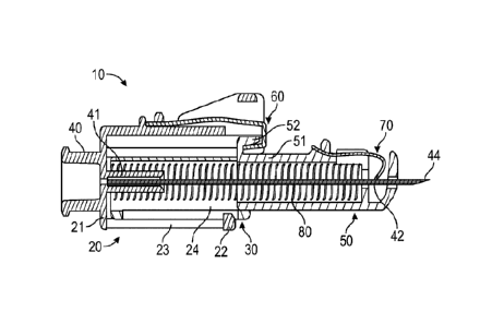
Date Recue/Date Received 2022-05-03
2
and depth to which the needle is inserted in the patient's tissue to be sure
that medication is
delivered to an appropriate location. In addition, there exists a tendency for
many practitioners
to falsely assume that they were "safe" from needle stick injuries, even in
the non-locked initial
state, due to the tip of the prior art retracting sheath safety needle devices
being fully covered
in an unlocked state.
[0005]
Thus, there is a need in the art to provide a safety needle device having a
passive
activation mechanism that overcomes the deficiencies of the known retracting
sheath safety
needle devices and which allows for shorter stroke distance, ease of use, low
part count, low
part complexity, relatively compact design, and clear and unobstructed view of
needle in an
initial position.
SUMMARY
[0006]
One aspect of the present disclosure pertains to a safety needle device
including
a housing configured to couple to a syringe. The housing includes a proximal
end, a distal end,
and a housing body. A needle hub may be disposed on the proximal end of the
housing and a
needle cannula may be attached to the needle hub. An activation latch may be
disposed on an
outer surface of the housing body and a retractable sheath may be disposed on
an inner surface
of the housing body. The retractable sheath may include a proximal end and a
distal end. A
retention shelf may be disposed on the proximal end of the retractable sheath.
A lockout latch
may be disposed on the retractable sheath to cover a distal tip of the needle
cannula. The
retention shelf is releasably engaged to the activation latch in an initial
position, wherein the
initial position partially exposes the distal tip of the needle cannula. A
spring element is
disposed in the housing body and attached to the distal end of the retractable
sheath. In one or
more embodiments, the safety needle device is a single use device. In one or
more
embodiments, the safety needle device is a passively activated device in which
the safety
features provide post-injection needle shielding without additional
intervention by the user.
[0007] In
one or more embodiments, the safety needle device may include a tether. In
one or more embodiments, the tether may be a telescoping tether. In one or
more
embodiments, the telescoping tether includes a first end attached to the
housing body and a
second end attached to the retractable sheath. In yet another embodiment, the
telescoping
tether includes a plurality of substantially concentric shells. The tether may
extend to form an
Date Recue/Date Received 2022-05-03
3
enclosure around the cannula as retractable sheath is moved distally along the
length of the
cannula.
[0008] In one or more embodiments, movement of the retractable sheath
from the
initial position to a retracted position disengages the activation latch of
the housing from the
retention shelf on the proximal end of the retractable sheath.
[0009] In one or more embodiments, the lockout latch may be a metal
latch.
[0010] In one or more embodiments, movement of the retractable sheath
from the
retracted position to an extended position engages the lockout latch to a
distal tip of the needle
cannula. The engagement of the lockout latch to the distal tip of the needle
cannula inhibits
.. reuse of the device by inhibiting translation of the retractable sheath.
The spring element
biases the retractable sheath toward the extended position.
[0011] In one or more embodiments, the retractable sheath translates
from the initial
position to the retracted position upon an active depression of the activation
latch.
[0012] In one or more embodiments, the needle cannula is obscured from
view when
the retractable sheath is in the extended position.
[0013] In one or more embodiments, the spring element may be a coil
spring.
[0014] Another aspect of the present disclosure pertains to a safety
needle device,
including a housing configured to couple to a syringe, the housing having a
proximal end, a
distal end, and a housing body. A needle hub may be disposed on the proximal
end of the
housing and a needle cannula may be attached to the needle hub. An activation
latch may be
disposed on an outer surface of the housing body and a slider element may be
positioned in a
longitudinal slot disposed over the activation latch. The longitudinal slot
may include a
forward slot end and a rear slot end. A retractable sheath may be disposed on
an inner surface
of the housing body, the retractable sheath having a proximal end and a distal
end. A retention
shelf may be disposed on the proximal end of the retractable sheath. A lockout
latch may be
disposed on retractable sheath to cover a distal tip of the needle cannula.
The retention shelf
releasably may be engaged to the activation latch in an initial position,
wherein the initial
position partially exposes the distal tip of the needle cannula; and a spring
element disposed in
the housing body and attached to the distal end of the retractable sheath.
[0015] In one or more embodiments, the slider element includes a contact
surface
having a profile for accommodating a practitioner's finger.
Date Recue/Date Received 2022-05-03
4
[0016] In one or more embodiments, the slider element may be in an
initial protective
position in which the slider element is at the forward slot end of
longitudinal slot and extends
over the distal end of the activation latch.
[0017] In one or more embodiments, the slider element may be in a non-
protective
position in which the slider element is at the rear end slot and extends over
the proximal end of
the activation latch allowing the activation latch to release from the
retention shelf of the
retractable sheath.
[0018] Another aspect of the present disclosure pertains to a method
of drug delivery
including obtaining the safety needle device described herein in a safe state
in which a distal
tip of a needle cannula is covered; requiring a practitioner to makes a first
choice whether to a)
fill the safety needle device with a desired liquid solution or b) Inject a
patient; requiring a
practitioner to makes a second choice based on the first choice to fill the
safety device; and
requiring a practitioner to makes a third choice based on the second choice.
[0019] In one or more embodiments, the second choice may be whether
to: a) fill the
safety needle device again, b) move the product to an inject state, or c) move
the product to a
transport state.
[0020] In one or more embodiments, after moving the product to the
transport state, the
safety device needle is moved to into a safe state. In one or more
embodiments, the safe state
includes placing a cap on the safety device needle.
[0021] Another aspect of the present disclosure pertains to a method of
drug delivery
including obtaining the safety needle device described herein in a safe state
having a needle
covered with a cap and a slider element positioned to prevent an activation
latch from
disengaging from a retention shelf of a retractable sheath; requiring a
practitioner to makes a
first choice whether to (a) fill the safety needle device by removing the cap
and sliding the
slider element over the activation latch to prevent activation latch from
disengaging from the
retention shelf of the retractable sheath while filling the device or (b)
inject by removing the
cap and insert the needle into a patient to deliver medication; requiring a
practitioner to makes
a second choice based on the first choice to fill the safety device; and
requiring a practitioner to
makes a third choice based on the second choice.
[0022] In one or more embodiments, the second choice may be whether to: a)
fill the
safety device needle repeatedly over a desired number of times, b) move the
product to an
inject state by sliding the slider mechanism off of the activation latch to
allow for the release of
Date Recue/Date Received 2022-05-03
5
the activation latch from the retention shelf on the retractable sheath during
inject state to allow
for retractable sheath with its protective clip to cover the distal tip of the
needle cannula, or c)
move the product to a transport state by re-capping the safety needle device
with a cap.
[0023] In one or more embodiments, the third choice may be whether to
actively
change the state of product by removing the cap and moving the slider element
to allow release
of the activation latch from the retention shelf on the retractable sheath to
the inject state.
BRIEF DESCRIPTION OF THE DRAWINGS
[0024] Fig. 1 illustrates an exploded view of a safety needle device
according to a first
embodiment;
[0025] Fig. 2 illustrates a perspective view of a safety needle device
shown in Fig. 1 in
an initial state;
[0026] Fig. 3 illustrates a sectional view of a first locking element
of the safety needle
device shown in Fig. 1;
[0027] Fig. 4 illustrates another a sectional view of a first locking
element of the safety
needle device shown in Fig. 1;
[0028] Fig. 5 illustrates a cross-sectional view of a safety needle
device according to a
first embodiment;
[0029] Fig. 6 illustrates another cross-sectional view of a safety
needle device
according to a first embodiment;
[0030] Fig. 7 illustrates a perspective view of a safety needle device
shown in Fig. 1 in
a retracted state;
[0031] Fig. 8 illustrates a perspective view of a safety needle device
shown in Fig. 1 in
an extended state; and
[0032] Fig. 9 illustrates a perspective view of a safety needle device
according to a first
embodiment.
[0033] Fig. 10 illustrates a perspective view of a safety needle
device according to a
first embodiment.
[0034] Fig. 11 illustrates a perspective view of a safety needle
device according to a
first embodiment.
[0035] Fig. 12 illustrates a perspective view of a safety needle device
according to a
first embodiment.
Date Recue/Date Received 2022-05-03
6
[0036] Fig. 13A illustrates a perspective view of a safety needle
device in a start
position according to a first embodiment.
[0037] Fig. 13B illustrates a perspective view of a safety needle
device in a finish
position according to a first embodiment.
[0038] Fig. 14A illustrates a perspective view of a safety needle device in
the finish
position according to a first embodiment.
[0039] Fig. 14B illustrates a perspective view of a safety needle
device in the start
position according to a first embodiment.
[0040] Fig. 15A illustrates a perspective view of a safety needle
device in the start
position according to a first embodiment.
[0041] Fig. 15B illustrates a perspective view of a safety needle
device in the locked
position according to a first embodiment.
[0042] Fig. 16 illustrates a perspective view of a safety needle
device according to a
first embodiment.
[0043] Fig. 17 illustrates a perspective view of a safety needle device
according to a
first embodiment.
[0044] Fig. 18 illustrates a perspective view of a safety needle
device according to a
first embodiment.
[0045] Fig. 19 illustrates a perspective view of a safety needle
device according to a
first embodiment.
[0046] Fig. 20 illustrates a flow diagram for 3 Choice Passive Safety
Device Functional
Architecture.
[0047] Fig. 21 illustrates a flow diagram for 3 Choice Passive Safety
Device Functional
Architecture with Slider Cap device.
[0048] Fig. 22 illustrates a schematic for 3 Choice Passive Safety Device
Functional
Architecture with Slider Cap device.
DETAILED DESCRIPTION
[0049] Before describing several exemplary embodiments of the present
disclosure, it
is to be understood that the embodiments of the present disclosure are not
limited to the details
of construction or process steps set forth in the following description. The
embodiments of the
Date Recue/Date Received 2022-05-03
7
present disclosure are capable of other embodiments and of being practiced or
being carried
out in various ways.
[0050] With respect to terms used in this disclosure, the following
definitions are
provided.
[0051] As used herein, the use of "a," "an," and "the" includes the
singular and plural.
[0052] In this disclosure, a convention is followed wherein the distal
end of the device
is the end closest to a patient and the proximal end of the device is the end
away from the
patient and closest to a practitioner.
[0053] As used herein, a "safety needle device" refers to a device
having a needle
suitable for injection that includes one or more features to prevent needle
stick injuries. As
used herein, a "passive safety needle" refers to a safety needle device with a
passive activation
mechanism that automatically covers the distal end of the needle after a
patient has been
injected.
[0054] Reference to "syringe" includes syringes that are indicated for
use with needles,
.. nozzle, tubing, or for use in flush systems. As used herein, the term
"syringe" refers to a
simple pump-like device consisting of a plunger rod that fits tightly in a
barrel or tube. The
plunger rod can be pulled or pushed along inside the barrel, allowing the
syringe to take in and
expel a liquid or gas through an opening at the open end of the barrel. The
open end of the
syringe may be fitted with a needle, nozzle, or tubing to help direct the flow
of fluid into and
out of the barrel. The syringe may be sterile or unsterile, depending upon the
needs of the
technician.
[0055] Embodiments of the safety needle device of the present
disclosure provides a
passive activation mechanism that overcomes the deficiencies of the known
retracting sheath
safety needle devices by allowing for a shorter stroke distance, ease of use,
increased patient
comfort, low part count, low part complexity, relatively compact design, and
clear and
unobstructed view of needle in an initial position.
[0056] Figs. 1-6 illustrate an exemplary safety needle device 10
according to the
present embodiments of the present disclosure. Safety needle device 10
includes a housing 20
configured to couple to a syringe (not shown). Housing 20 having a proximal
end 21, a distal
end 22, a housing body 23 and an opening 24 located on the distal end. Tether
30 is disposed
on the housing body 23. Tether 30 is generally parallel to a central axis
which extends along
the housing body 23.
Date Recue/Date Received 2022-05-03
8
[0057] Housing 20 may be of a unitary construction or may be formed
from a plurality
of components. In one or more embodiments, a proximal end 21 and a distal end
22 of the
housing 20 can be separate components that are joined using techniques, such
as but not
limited to sonic welding, adhesive, snap or press fitting, or the like.
[0058] Needle hub 40 is disposed on the proximal end 21 of the housing 20.
Needle
cannula 42 is attached to the needle hub 40. In one or more embodiments, the
proximal end 21
of the housing 20 may be connectable to a luer connection or other fluid
connector. As shown
in Fig. 1, distal end 22 of housing 20 couples to a retractable sheath 50 such
that the retractable
sheath 50 is configured to move along a central axis in housing body 23. A
channel and an
aperture are included in the retractable sheath 50 in order to permit the
needle cannula 42 and
distal tip 44 of needle cannula 42 to pass therethrough.
[0059] Retractable sheath 50 is slidably mounted and movable in the
opening 24 of the
housing body to slidably accommodate and encase needle cannula 42 projecting
axially from
housing 20. The proximal end of retractable sheath 50 includes a stop or
retention shelf 52
configured to allow the retractable sheath to move between an initial
position, a retracted
position and an extended position with respect to the housing 20, wherein the
initial position
partially exposes a distal tip 44 of the needle cannula 42, the retracted
position fully exposes
the needle cannula 42, and the extended position fully covers the distal tip
44 of the needle
cannula 42. In one or more embodiments, the stop or retention shelf 52 may be
in the shape of
.. a hook. The term "retractable sheath" is intended to include any sort of
tubular member and U-
shaped member. The retractable sheath 50 is dimensioned to be compatible with
the size and
type of needle cannula 40 as will be appreciated by those skilled in the art.
The housing 20
includes a housing body 23 with an internal hollow region in which the
retractable sheath 50
may move in the proximal and distal direction.
[0060] Fig. 1 illustrates a safety needle device 10 that may be removably
coupled to a
standard or specially configured syringe (not shown). Although the illustrated
safety needle
device 10 is configured to be coupled to and removed from a syringe, the
safety needle device
10 may instead be integrally formed with the syringe. The syringe is generally
of a known
type suitable for the withdrawal and injection and/or aspiration of fluids or
other solutions by
way of the safety needle device 10.
[0061] Referring now to Fig. 1-2, the safety needle device 10 is
illustrated in an initial
state wherein the retractable sheath 50 is in a partially retracted
configuration. Further
Date Recue/Date Received 2022-05-03
9
retraction of the retractable sheath 50 is generally initiated by a
practitioner applying pressure
on the safety needle device 10 and/or syringe in the distal direction, which
thereby encourages
the retractable sheath 50 proximally against the bias of the spring element
80. This retraction of
the retractable sheath 50 in turn further exposes the distal tip 44 of the
needle cannula 42 and
initiates penetration by the needle cannula 42 into the patient's skin.
[0062] As shown in Fig. 1, needle cannula 42 may be connected to a
needle hub 40
disposed at the proximal end 21 of the housing 20 and having a blunted tip
(not shown) or
beveled tip (as shown in Fig. 1) at the distal tip 44 of needle cannula 42.
The needle cannula
42 is disposed in the needle hub 40 in a manner as would be well understood in
the art. The
needle hub 40 may be integrally formed with the proximal end 21 of housing 20.
Needle hub
40 may be configured to be removable or permanently attached to the syringe,
or alternatively,
needle hub 40 may be integrally formed with the syringe. For example, needle
hub 40 may
include internal or external threads or other suitable coupling, latching, or
locking features
such as tabs, slots, projections, pressure/snap fits, and the like, for
removably coupling the
safety device to a syringe. In some embodiments, the housing 20 includes a
generally
cylindrically reduced needle support 41 that extends axially from the needle
hub 40 to support
the needle cannula 42. Housing 20 and/or needle hub 40 are in fluid
communication with the
needle cannula 42 to permitting fluid to pass between the syringe and the
needle cannula 42.
[0063] The needle cannula 42 extends from the needle hub 40 disposed
in the housing
20 and extends to a distal tip 44. In an initial state, as shown in Figs. 1-3,
the distal tip 44 of
the needle cannula 42 is partially exposed and protruding from the distal end
of the retractable
sheath 50 so as to be visible when the retractable sheath 50 is in an initial
position, as shown in
Figs. 1-3. The shaft of the needle cannula 42 is increasingly fully exposed
from the retractable
sheath 50 when the retractable sheath 50 is in a retracted position.
[0064] As illustrated in several of the drawings, most notably Figs. 1 and
2, retractable
sheath 50 is generally comprised of a tubular portion and is slidably
retractable along the
length of the needle cannula 42 such that a distal tip 44 of the needle
cannula 42 is partially
exposed and protruding from the distal end of the retractable sheath 50 when
in an initial
position so as to be visible to a practitioner. A substantial or entire
portion of needle cannula
42 is exposed when the retractable sheath 50 is in its retracted position. The
length of needle
cannula 42 which extends from the needle hub 40 in a distal direction is
completely encased
when retractable sheath 50 is in its extended position, as shown in Fig. 6.
Date Recue/Date Received 2022-05-03
10
[0065] The needle cannula 42 in accordance with the present disclosure
can be formed
from conventional materials such as steel or more preferably stainless steel.
It will be realized
by the skilled artisan that medical grade plastics, composites, ceramics, or
like materials can be
substituted.
[0066] The inside diameter of the retracting sheath 50 is selected so that
it will fit
closely over needle cannula 42. The retracting sheath 50 may be made of any
suitable material,
but preferably of a polymer which is tough enough to protect needle cannula
42.
[0067] The proximal end 51 of retractable sheath 50 includes a
retention shelf 52 that
extends radially outward from the proximal end of retractable sheath 50 and is
configured to
.. engage the activation latch 60 of the housing body 23. As shown in Figs. 1
and 2, housing 20
has an opening that receives the retractable sheath 50.
[0068] In one or more embodiments, retractable sheath 50 may be
disposed and
movable in the housing body 23. The retractable sheath 50 is spring loaded,
and is supplied to
the practitioner with the retracting sheath 50 partially covering the needle
cannula 42 so that
the distal tip of the needle cannula is exposed and visible in an initial
state, as shown in Fig. 2.
Upon administration of the injection, the retractable sheath 50 moves from an
initial position
whereby the distal tip 44 of the needle cannula 42 is exposed to a retracted
position whereby
the needle cannula is increasingly exposed so that the needle cannula may
penetrate the
injection site.
[0069] One aspect of the present disclosure pertains to a safety needle
device that
allows for either "Inject Only" or "Integrated Fill and Inject" procedures for
fluids, including
fluids and solutions used in medical procedures. As shown in Figs. 1 and 2,
one or more
embodiments of the safety needle device 10 include an activation latch 60 in
combination with
a spring element 80. As shown in Figs. 3-6, in the initial state both the
activation latch 60 and
the spring element 80 hold stored energy. Upon beginning injection, the energy
in the
activation latch 60 is released once the retention shelf 52 on the proximal
end of the retractable
sheath 50 is released from engagement with the activation latch 60 upon a
practitioner
depressing the activation latch over a very short distance.
[0070] Once the activation latch 60 is released from the retention
shelf 52 on the
proximal end of the retractable sheath 50, the practitioner can continue to
inject the cannula to
their desired depth in a patient or vial by either utilizing the full length
of the needle or a
significantly shorter distance of the needle cannula. Upon removing the needle
cannula 42
Date Recue/Date Received 2022-05-03
11
from a patient, the retractable sheath 50 automatically advances forward and
the stored energy
in the spring element 80 is released allowing retractable sheath 50 to
continues to be pushed
forward until the lockout latch 70 is able to clip over the distal tip 44 of
the needle cannula 42
thereby passively locking out the safety needle device 10 and preventing
needle stick injury to
the practitioner. In one or more embodiments, activation latch 60 may be a
metal latch. In
one or more embodiments, lockout latch 70 may be a metal latch.
[0071] As shown in Figs. 3-6, in one or more embodiments, safety
needle device 10
may operate in an" Inject Only" state, wherein the safety needle device 10
passively locks out
after one compression of retractable sheath 50 upon release of the activation
latch 60 from
retention shelf 52.
[0072] During administration of an injection to a patient, the
application of force on the
needle device by the practitioner in the distal direction and/or depression of
the activation latch
60 by the practitioner causes the retractable sheath 50 to move in a proximal
direction. In or
more embodiments, the retractable sheath translates from the initial position
to the retracted
position without impediment. A continued application of force by the
practitioner in the distal
direction causes activation latch 60 to disengage from the retention shelf 52
thus activating the
lockout latch 70. In one or more embodiments, the lockout latch 70 includes a
metal latch on
a distal end of the retractable sheath. Movement of the retractable sheath
from the initial
position to the retracted position disengages the activation latch 60 from the
retention shelf 52.
.. In some embodiments, the activation latch 60 is generally resilient, so
that the radially
inwardly disposed second ends can flex and then return to the original
position even after the
ends have been radially outwardly deflected. In one or more embodiments, the
activation latch
60 may include a latching member, such as a shelf, clasp, detent, ratchet, or
other structure.
[0073] Upon completion of an injection to the patient, the
practitioner withdraws the
needle cannula from the patient, thus causing the stored energy of spring
element 80 to allow
the retractable sheath 50 to proceed to fully covers needle cannula 42 in the
extended position.
The spring element 80 biases the retractable sheath 50 in a distal direction
to cover the distal
tip 44 of needle cannula 42 causing activation of the lockout latch 70 to
prevent further
translational movement of the retractable sheath 50 within the housing body
23. Movement of
the retractable sheath from the retracted position to the extended position
engages the lockout
latch 70 to a distal tip of the needle cannula.
Date Recue/Date Received 2022-05-03
12
[0074] In one or more embodiments, the lockout latch 70 is disposed on
the retractable
sheath and rides along the needle cannula until the lockout latch 70 covers
the distal tip 44 of
the needle cannula 42 in the extended position. In one or more embodiments,
the retractable
sheath 50 extends in length beyond the lockout latch 70, as seen in Fig. 1. In
one or more
embodiments, lockout latch 70 comprises a protective clip which can cover the
distal tip 44 of
the needle cannula 42 in the extended position. In one or more embodiments,
the lockout latch
70 inhibits reuse of the safety needle device 10 by inhibiting further
translational movement of
the retractable sheath 50 within the housing body 23 by covering the distal
tip 44 of the needle
cannula 42 in the extended position. Needle cannula 42 is obscured from view
when the
retractable sheath is in the extended position. As shown in Fig. 6, as the
injection is completed
and the distal tip 44 of needle cannula 42 is pulled from injection site, the
stored force of
spring element 80 causes the retracting sheath 50 to extend, and at the end of
the stroke, a
lockout latch extends over the distal tip of the needle cannula 42 to lock the
retractable sheath
50 thereby completing a passive safety lock-out. In one embodiment, the
lockout latch is a
metal clip.
[0075] Spring element 80 includes a proximal end, a main body, and a
distal end. In
one or more embodiments, as shown in Fig. 1, spring element 80 comprises a
compression or
coil spring. The spring element 80 biases the retractable sheath toward the
extended position.
[0076] In one or more embodiment, spring element 80 engages and
extends between
the proximal end of the retractable sheath and the proximal end of the
housing. The spring
biases the retractable sheath 50 toward an initial position in which the
retention shelf 52 of the
retractable sheath 50 is biased into engagement with the activation latch
located at the distal
end of the housing body 23 thereby allowing the distal tip 44 of the needle
cannula 42 to be
exposed and visible in the initial position. The retractable sheath 50
completely covers the
distal tip 44 of the needle cannula 42 in the extended position. Many types of
springs may be
employed, such as but not limited to a helical coil spring, conical spring,
wave-spring, or the
like. In some embodiments, the spring element 80 is configured to facilitate
retraction of the
retractable sheath 50 by a practitioner applying distal pressure to the
syringe and/or the safety
needle device 10 with just one hand.
[0077] Safety needle device 10, and components thereof, can be formed using
many
manufacturing processes sufficient to provide the desired shape of the
components. In some
embodiments one or more components are made by a molding process, such as but
not limited
Date Recue/Date Received 2022-05-03
13
to injection molding, compression molding, blow molding, transfer molding, or
similar. In
some embodiments, one or more components are formed by forging, machining,
casting,
stamping, extrusion, a combination thereof, or the like.
[0078] In many embodiments, the safety needle device 10 is constructed
from a
biocompatible material. In some arrangements one or more of the components of
the safety
needle device 10 are plastic (e.g. polyurethane, etc.) or metal (e.g.,
stainless steel, etc.). In
some embodiments, the housing 20 and/or the retractable sheath 50 are
constructed of
materials that are either translucent or opaque.
[0079] In some embodiments, movement of the retractable sheath 50 to
disengage the
retention shelf of the retractable sheath from activation latch 60 will allow
for automatically
engagement of lockout latch 70 with the distal tip 44 of needle cannula 42. In
some
embodiments, movement of the retractable sheath 50 from an about fully
retracted position to
an about fully extended position automatically prevents or inhibits reuse of
the safety needle
device 10.
[0080] In embodiments in which housing 20 comprises multiple pieces, the
manufacturing process can include the step of assembling the housing 20. A
retractable sheath
is formed having retention shelf 52 which is aligned for engagement with
activation latch 60.
The retractable sheath 50 is slidingly moved through the opening 24. The
needle cannula 42 is
coupled with the needle support 41 of the housing 20. The spring element 80 is
inserted into
the housing body 23 and positioned to bias the retractable sheath 50.
[0081] As shown in Fig. 5, as the retractable sheath 50 continues to
retract into the
housing body 23, to further expose the needle cannula 42. Upon withdrawal of
the needle
cannula 42 from the patient, the stored spring energy of the spring element 80
to distally
extend the retractable sheath 50. As the retractable sheath 50 distally
extends, it covers the
needle cannula 42 into the channel of the hub body thereby covering the distal
end of the
needle cannula 42. As shown in Fig. 6, upon reaching the retractable sheath 50
reaching the
distal tip 44 of the needle cannula 42, the lockout latch 70 moves distally
over the distal tip to
cover the distal tip 44 of the needle cannula 42 to prevent reuse of the
safety needle device 10.
The retractable sheath 50 has been fully extended and fully covers the needle
cannula 42. The
.. lockout latch 70 thus presents a physical stop to inhibit the retractable
sheath 50 from being
proximally retracted again.
Date Recue/Date Received 2022-05-03
14
[0082] Another aspect of the present disclosure pertains to a safety
needle device
having a telescoping tether having a first end secured to the hub or housing
and a second end
secured to the retractable sheath. In one more embodiments, incorporation of a
telescoping
tether allows the overall size of the safety needle device to be significantly
reduced. Figs. 1-12
and 19 show a perspective view of another embodiment having a tether 30.
[0083] As shown in Figs. 1-12 and 19, safety needle device 10 further
comprises a
tether 30, which connects the housing 20 and is telescoping. As the
retractable sheath 50
moves distally along the needle cannula 42, the tether 30 extends to the
length of the needle
cannula 42. The tether 30 thus provides an extensible length beyond which the
housing 20 may
not distally extend.
[0084] The tether 30, having a proximal end and a distal end, may have
the proximal
end affixed to housing 20 or hub 40 and the distal end of the tether may be
affixed to the
retractable sheath 50 by any suitable fastening mechanism including, but not
limited to
adhesives, point welding, rivets, and heat sealing. In one or more
embodiments, tether 30 may
be in the form of a tube or concentric cone-shaped enclosures. The tether 30
deploys in the
form of a tube or cone-shaped enclosure around the needle cannula 42. Tether
30 extends to
form an enclosure around the cannula as retractable sheath is moved distally
along the length
of the cannula.
[0085] Other configurations for the tether 30 are possible. In one or
more
embodiments, as shown in Fig. 19, tether 30 may comprise a plurality of
substantially
concentric shells. In one or more embodiments, tether 30 distally extends
along the needle
cannula 42, and the concentric shells (32, 34, and 36) of the tether 30 slide
past each other to
cover or completely envelope the needle cannula 42. In one or more
embodiments, the tether
extends to form a substantially cone-shaped enclosure around the cannula as
the retractable
sheath is moved distally along the length of the cannula. In certain
embodiments, the tether is a
plurality of substantially concentric shells which are axially telescoping and
envelope the
cannula as the retractable sheath is moved distally along the length of the
cannula.
[0086] As shown in Fig. 19, tether 30 may include a plurality of
concentric shells 32,
34, 36. The outermost concentric shell 32 may be affixed to the inner surface
of the housing 20
.. or needle hub 40, and the innermost concentric shell 36 may be affixed to
the retractable sheath
50. Concentric shells 32, 34, 36 are designed to telescopically slide with
respect to each other,
but not to extend past each other, and the total extension length of the
tether 30 is long enough
Date Recue/Date Received 2022-05-03
15
to permit the retractable sheath 50 to cover the length of needle cannula and
for lockout latch
70 to extend over and cover the distal tip 44 of the needle cannula. Tether 30
is configured to
fully cover needle cannula 42 when the retractable sheath is maximally
extended to cover and
shield the distal tip 44 of the needle cannula.
[0087] Another aspect of the present disclosure pertains to housing 20
further includes
a slider element 100 that extends over activation latch 60 extending radially
from an external
surface of housing 20.
[0088] As shown in Figs. 7-12, safety needle device 10 is configured
to enable "fill and
inject" wherein activation latch 60 is held down when the safety needle device
10 is in the fill
.. state so that retention shelf 52 on the proximal end of the retractable
sheath 50 remains
engaged to the activation latch 60 after each fill. As shown in Figs. 7-12, in
one or more
embodiments, safety needle device 10 may include a slider element 100 to hold
down
activation latch 60 to ensure that retention shelf 52 on the proximal end of
the retractable
sheath 50 remains engaged to the activation latch 60, thus preventing the
stored energy in the
activation latch 60 from being released. In yet another embodiment, slider
element 100 may be
configured to toggle in a perpendicular direction with respect to the needle
cannula.
[0089] Desirably, activation latch 60 is integrally formed with
housing 20 extending
from an outer surface of hub body. Slider element 100 may also include a
contact surface
having a profile for accommodating a practitioner's finger. As shown in Figs.
7-12, slider
element 100 is positioned in a longitudinal slot 110, with finger surface
extending beyond
longitudinal slot 64 at the outer surface of housing 20.
[0090] Safety needle device 10 is capable of assuming a position for
protection and a
position for use by way of translating the slider element 100 from an initial
protective position
in which the slider element 100 is at the forward slot end of longitudinal
slot and extends over
.. the distal end of the activation latch to moving the slider element in an
proximal direction such
that the slider element extends over the proximal end of the activation latch
thus allowing the
activation latch from releasing from the slot of the retractable sheath. To
prevent retractable
sheath 50 from being released from the initial position, slider element 100 is
at the forward slot
end thus preventing activation latch 60 from releasing from retention shelf 52
of retractable
.. sheath 50. Activation latch 60 locks retractable sheath 50 through
engagement with retention
shelf 52 disposed on the proximal end of retractable sheath 50 when slider
element 100 is
located at the forward slot end of longitudinal slot, as shown in Fig. 10.
Date Recue/Date Received 2022-05-03
16
[0091] Once the use moves the slider element 100 at the rearward slot
end thus
allowing the release of activation latch 60 from the retractable sheath 50
once the retractable
sheath is moved in a proximal direction during the administration of an
injection to a patient.
Upon activation, activation latch 60 releases retractable sheath 50 when
activation latch 60 is
no longer in an interference engagement with the retention shelf 52 disposed
on the proximal
end of retractable sheath 50.
[0092] Movement of the activation latch from a forward slot end to the
rearward slot
end disengages the enlarged portion of the protective clip from interference
engagement with
retention shelf 52 of the retractable sheath. This releases retractable sheath
from the locked
position, thus allowing free movement of retractable sheath 50 within the
housing toward the
distal tip 44 of needle cannula 42. In one or more embodiments, this may be
accomplished by
exerting pressure on finger contact surface of the activation latch 60.
[0093] Distal tip 44 of needle cannula 42 is completely covered by the
protective clip
of the retractable sheath to prevent re-exposure thereof without any further
action on the part of
the practitioner.
[0094] Safety needle device 10 may include means for storing energy
extending
between housing 20 and retractable sheath 50, such that upon release of the
activation latch,
retractable sheath 50 is automatically forced forward along longitudinal axis
thereby
automatically enabling shielding of needle cannula 42.
[0095] The means for storing energy may be a spring element 80, such as a
compression spring. Spring element 80 may extend between the distal end of
retractable
sheath 50 and proximal end of housing 20.
[0096] The needle safety device of the present disclosure provides a
simple mechanism
for causing actuation of the shielding feature with a single hand of the
practitioner.
[0097] In yet another embodiment, as shown in Figs. 13-18, a blocking
member 120
may utilized in combination with a spring element to pivot that blocking
member 120 in order
to achieve lockout and thereby preventing the needle from re-finding the hole.
In one or more
embodiment, blocking member 120 as housed inside the sheath as shown in figs.
13 and 14. In
one or more embodiment, blocking member 120 may be configured as an integrated
block that
utilizes a living hinge as shown in Fig. 15. As shown in Figs. 13 and 14, a
sheath may be used
that that utilizes the energy in a spring element to bias the sheath upon
lockout so that the
needle and the hole are no longer co-axial preventing it from once again
finding the hole. In
Date Recue/Date Received 2022-05-03
17
one or more embodiments, blocking member 120 may be configured as an angled
plastic
component.
[0098] In one or more embodiments, as shown in Figs. 13-15, blocking
element
comprises a block having a diagonal channel within the body of the blocking
element attached
to spring element is provided. In an initial state, the cannula is threaded
through the diagonal
channel such allowing the distal tip of the cannula to protrude from the
distal end of the
retractable sheath 50 such that distal tip of the cannula is visible to the
practitioner while the
spring element exerts force on blocking element to maintain the blocking
element in a biased
state at the distal end of the retractable sheath 50. Upon administration of
an injection to a
patient, the retractable sheath 50 moves in a proximal direction such that the
needle cannula
moves out of the diagonal channel allowing the blocking member to rotate to an
unbiased state
such that the cannula is prevented the distal tip 44 of needle cannula 42 from
re-entering the
diagonal channel within the body of the blocking element to prevent exposure
of the
practitioner from the distal tip 44 of needle cannula 42. It will be
appreciated that the blocking
element may be mounted to a spring element, or it may be an integral part of,
the distal end of
the retractable sheath 50.
[0099] If the distal tip of the cannula attempts to pass back through
the diagonal
channel, the distal tip will be buttressed by the body of the blocking member
thus causing the
distal tip to remain safely disposed within the housing 20 and prevented by
the tether 30 and
blocking member from exiting the confines of the housing 20.
[00100] When the needle cannula 42 is withdrawn from the patient, the
patient's skin no
longer obstructs forward movement of the retractable sheath 50, and the
retractable sheath 50
then moves to the extended position as shown in Fig. 14. As shown in Figs. 13-
15, the
retractable sheath 50 has an opening through which the needle cannula 42
extends in an initial
position.
[00101] The misalignment of the needle cannula 42 with the diagonal
channel prevents
the needle cannula 42 from extending back out of the diagonal channel after
use. Furthermore,
the blocking element may be made of strong material to prevent the distal tip
44 of the needle
cannula 42 from piercing through the blocking element.
[00102] In one or more embodiments, the safety needle device 10 can include
a cap that
is removably coupled to the housing 20 to reduce or prevent contamination of
the needle
cannula during shipping and storage of the safety needle device 10. The cap is
generally kept
Date Recue/Date Received 2022-05-03
18
in the closed position until just prior to an injection and/or aspiration
procedure, at which time
the cap is removed from the housing 20.
[00103] It is also envisioned that in one or more embodiments of the
present disclosure,
safety needle device 10 does not included includes a tether 30. In such an
embodiment,
housing 20 has a proximal end 21, a distal end 22, a housing body 23 and an
opening 24
located on the distal end. Distal end 22 of housing 20 couples to a
retractable sheath 50 such
that the retractable sheath 50 is configured to move along a central axis in
housing body 23. .
[00104] Any suitable caps or packaging comprising a safety feature may
be used in
conjunction with the safety needle device disclosed herein. Any suitable caps
or packaging
comprising a safety feature may be used in conjunction with the safety needle
device disclosed
herein. Types of safety features vary in structure and mechanics but exemplary
caps or
packaging include, but are not limited to, those described in commonly owned,
U.S. Patent
Application Serial Nos., 62/433,044, 62/433,526 and 62,433,297.
[00105] Another aspect of the present disclosure pertains to a "3
Choice" Passive Safety
Device Functional Architecture which allows a practitioner to both fill and
inject with the same
needle safety device. During this process the practitioner has the opportunity
to make 3
choices throughout the use of needle safety device. Fig. 20 illustrates a flow
diagram for 3
Choice Passive Safety Device Functional Architecture. Fig. 21 illustrates a
flow diagram for 3
Choice Passive Safety Device Functional Architecture with Slider Cap device.
Fig. 22
illustrates a schematic for 3 Choice Passive Safety Device Functional
Architecture with Slider
Cap device.
[00106] As shown in Fig. 20, to start 200, a safety needle device comes
packaged in a
safe state 201 in which the needle is covered and prevents needle stick injury
(NSI) 206. This
can be in the form of a hard-pack or in a blister with a separate cap 202. At
this point the
practitioner makes the first choice: whether to a) Fill 203(e.g. access a vial
to fill a syringe or
transfer fluids) or b) Inject 204 (insert the needle into a patient to deliver
medication). In one
or more embodiments, at the first choice, the practitioner may actively change
the safety needle
device to that state by either activating the activation latch or sliding the
slider mechanism to
release the activation latch from the retention shelf on the retractable
sheath as discussed
above. Assuming the practitioner chooses to Fill 203, once they complete
filling, they now
make the second choice whether to: a) fill 203 the safety needle device again
(e.g. perform
another vial access), b) move the product to an inject state 204, or c) move
the product to a
Date Recue/Date Received 2022-05-03
19
transport state 205. In one or more embodiment, each of these choices requires
an active
motion by the practitioner. Assuming the practitioner chooses to move the
product to the
transport state 205, they now place the safety device needle into a safe state
201 that could
prevent NSI's 206 (e.g. place a cap 202 on the safety device needle).
Following transportation,
the practitioner then needs to make the third choice: whether to actively
change the state of
product (e.g. move the slider element to allow release of the activation latch
from the retention
shelf on the retractable sheath) to the inject state 204. Once in the inject
state 204, within
approximately the first 5mm or less of the needle penetrating the patient's
skin (or other
medium) the device will automatically lock out 220 by allowing the retractable
sheath with its
.. protective clip to cover the distal tip of the needle cannula ¨ thereby
defining passive safety
221. In one or more embodiments, "Fill", "Inject" and "Trash" symbols will be
depicted on the
safety device needle such that the slider will point to each during that
state.
[00107] As shown in Fig. 21 and Fig. 22, to start 200, a safety needle
device comes
packaged in a safe state 201 in which the needle is covered with a cap 202,
along with a slider
element that may be positioned to prevent activation latch from disengaging
from the retention
shelf of the retractable sheath, as discussed above, to prevent needle stick
injury (NSI) 206.
At this point the practitioner makes the first choice: whether to a) Fill 203
(e.g. access a vial to
fill a syringe or transfer fluids) by removing the cap 207a and sliding the
slider element 207b
over the activation latch to prevent activation latch from disengaging from
the retention shelf
of the retractable sheath while filling the device or b) Inject 204 (e.g.
removing the cap 208 and
insert the needle into a patient to deliver medication). In one or more
embodiments, at the first
choice, the practitioner may actively change the safety needle device to
either a fill state 203
(e.g. by sliding the slider element 207b over the activation latch to prevent
release of the
activation latch from the retention shelf on the retractable sheath while
filling or actively
.. changing the safety needle device) or to an inject state 204 (e.g. by
sliding the slider
mechanism off 209 of the activation latch to allow for the release of the
activation latch from
the retention shelf on the retractable sheath during inject state to allow for
retractable sheath
with its protective clip to cover the distal tip of the needle cannula ¨
thereby defining passive
safety 221. Assuming the practitioner chooses to Fill 203, once they complete
filling, they
now make the second choice whether to: a) fill the safety device needle
repeatedly over a
desired number of times 210 (e.g. perform another vial access), b) move the
product to an
inject state 204 by sliding the slider mechanism off 209 of the activation
latch to allow for the
Date Recue/Date Received 2022-05-03
20
release of the activation latch from the retention shelf on the retractable
sheath during inject
state to allow for retractable sheath with its protective clip to cover the
distal tip of the needle
cannula, or c) move the product to a transport state 205 by re-capping 223a
the safety needle
device with a cap 223b. In one or more embodiment, each of these choices
requires an active
motion by the practitioner. Assuming the practitioner chooses to move the
product to the
transport state 205, they now place the safety device needle into a safe state
201 that could
prevent NSI's 206 (e.g. place a cap on the safety device needle). Following
transportation, the
practitioner then needs to make the third choice: whether to actively change
the state of
product (e.g. removing the cap and moving the slider element 209 to allow
release of the
activation latch from the retention shelf on the retractable sheath) to the
inject state 204. Once
in the inject state 204, within approximately the first 5mm or less of the
needle penetrating the
patient's skin (or other medium) the device will automatically lock out 220 by
allowing the
retractable sheath with its protective clip to cover the distal tip of the
needle cannula 222¨
thereby defining passive safety 221.
[00108] Fig. 22 shows the safety needle device in an initial state 205 and
transfer state
205 (with cap positioned on the safety needle device); inject state 204
(distal tip of the needle
cannula partially exposed and visible to the practitioner); fill state 203
(needle cannula fully
exposed); and trash state 221 (with the distal tip of the needle cannula fully
covered by the
retractable sheath and protective clip.
[00109] In one or more embodiments, symbols for "Fill", "Inject", and
"Trash" may be
depicted on the safety needle device. In one or more embodiments, slider
element 100 will
point to the appropriate symbol for "Fill", "Inject", or "Trash" to indicate
the status of the
safety needle device. In one or more embodiments, safety needle device comes
packaged with
a cap in an Inject State with only the needle tip exposed. To inject, remove
the cap and inject
.. after which the safety needle device permanently locks out. To Fill,
practitioner moves the
slider element from the "Inject" to "Fill" Symbol and fill an infinite number
of times during
which no force will be imparted on the vial. To Transfer the safety needle
device, the
practitioner places the cap back onto the safety needle device.
[00110] Whenever the safety needle device is in a "fill state" it is in
a state that allows
for potential needle stick injury and when the needle enters into a vial (or
other medium) and
then exits, it does not lock. This means that a practitioner could access a
vial to fill an infinite
number of times. Similarly, whenever the device is in an "inject state" it is
in a state that also
Date Recue/Date Received 2022-05-03
21
allows for potential needle stick injury. However, once the needle enters into
a patient (or
other medium) then then exits it automatically locks after 1 time.
[00111] A practitioner can move the Inject State at any point in the
process. This means
that the practitioner can go from state to inject, fill to inject, or
transport to inject as indicated
above.
[00112] As shown in Figs. 20-22, the needle safety device is delivered
to the practitioner
in a safe state packaging in which the needle is covered and thus prevents
needle stick injury
(NSI). Packaging can be in the form of a hard-pack or in a blister with a
separate cap. At this
point the practitioner makes the first choice: to either a) "Fill" by
accessing a vial to fill a
syringe or transfer fluids, or b) Inject by inserting the needle into a
patient to deliver
medication ¨ and they actively change the device to that state. Assuming the
practitioner
chooses to Fill, once they complete filling, they now make a second choice:
whether to a) fill
again by performing another vial access; b) move the product to an inject
state, or c) move the
product to a transport state. Both the first choice and the second choice
require an active
motion by the practitioner. If the practitioner chooses to move the product to
the transport
state, the practitioner places the needle safety device into a safe state that
could prevent needle
stick injury (NSI). Following transportation, the practitioner can
subsequently make a third
choice: whether to actively change the needle safety device to an inject
state. Once the needle
safety device is in the inject state, within approximately the first 5mm or
less of the needle
penetrating the patient's skin (or other medium) the needle safety device will
automatically
lock out.
[00113] While the needle safety device is in a "fill state", safety
needle device may
allow for potential needle stick injury because as the needle of the needle
safety device enters
into a vial (or other medium) and then exits, the needle safety device does
not lock. This
means that a practitioner could access a vial to fill an infinite number of
times.
[00114] Similarly, whenever the safety needle device is in an "inject
state" it is in a state
that also allows for potential needle stick injury. However, once the needle
enters into a
patient (or other medium) then then exits it automatically locks after 1 time.
[00115] In one or more embodiments, the practitioner can move the
needle safety device
into the Inject State at any point in the process. Thus, the practitioner can
actively transition
from inject to fill, fill to inject, or transport to inject.
Date Recue/Date Received 2022-05-03
22
[00116] In
one embodiment, a needle safety device having a slider element along with a
cap may be packaged to Inject. However, if the practitioner decides to fill
the safety needle
device, the practitioner may proceed to fill after removing the cap from the
needle safety
device. Alternatively, if the practitioner decides to proceed directly to an
inject state, the
practitioner may proceed to inject after removing the cap from the needle
safety device,
whereby after the injection is completed the safety needle device would
proceed to a
permanent lock out state. Similarly to fill prior to injection, the
practitioner would need to
move the axial slider from the Inject to Fill State, fill as many times as the
practitioner desired,
and then the practitioner would proceed to move the axial slider back to the
inject state prior to
injection. In one or more embodiments, the slider would have a pointer and
symbols and/or
verbiage to help guide the practitioner. If transport of the needle safety
device is desired
between fill and inject, the practitioner would need to recap the needle.
[00117]
This passive safety activation will help to reduce the incident of
contaminated
needle stick injuries by ensuring that the device automatically locks after
injection when used
as intended. Additionally, the needle safety device allows practitioners to
fill and inject within
one product allowing for reduced materials, time savings, and a reduction of
cost to clinicians.
Additionally, embodiments of the present disclosure allow for utilization of a
greater distance
of the needle to fill allowing it to penetrate more stoppers that are on the
currently available, as
well as, providing a more "immediate" lock out when injecting a patient.
[00118]
Reference throughout this specification to "one embodiment," "certain
embodiments," "various embodiments," "one or more embodiments" or "an
embodiment"
means that a particular feature, structure, material, or characteristic
described in connection
with the embodiment is included in at least one embodiment of the disclosure.
Thus, the
appearances of the phrases such as "in one or more embodiments," "in certain
embodiments,"
"in various embodiments," "in one embodiment" or "in an embodiment" in various
places
throughout this specification are not necessarily referring to the same
embodiment of the
disclosure. Furthermore, the particular features, structures, materials, or
characteristics may be
combined in any suitable manner in one or more embodiments.
[00119]
Although the disclosure herein provided a description with reference to
particular embodiments, it is to be understood that these embodiments are
merely illustrative of
the principles and applications of the disclosure. It will be apparent to
those skilled in the art
that various modifications and variations can be made to the present
disclosure without
Date Recue/Date Received 2022-05-03
23
departing from the spirit and scope thereof. Thus, it is intended that the
present disclosure
include modifications and variations that are within the scope of the appended
claims and their
equivalents.
Date Recue/Date Received 2022-05-03