Note: Descriptions are shown in the official language in which they were submitted.
CA 03047066 2019-06-13
WO 2018/140058
PCT/US2017/015639
GAP SUB IMPEDANCE CONTROL
BACKGROUND
[00011 Wellbores drilled into subterranean formations may enable recovery of
desirable fluids (e.g., hydrocarbons) using a number of different techniques.
Knowing the
location of a target wellbore may be important while drilling a second
wellbore. For
example, in the case of a target wellbore that may be blown out, the target
wellbore may
need to be intersected precisely by the second (or relict) wellbore in order
to stop the blow
out. Another application may be where a second wellbore may need to be drilled
parallel
to the target wellbore, for example, in a steam-assisted gravity drainage
("SAGD")
operation, wherein the second wellbore may be an injection wellbore while the
target
wellbore may be a production wellbore. Yet another application may be where
knowledge
of the target wellbore's location may be needed to avoid collision during
drilling of the
second wellbore.
[0002] Electromagnetic induction tools disposed on bottom hole assemblies may
be employed in subterranean operations to determine direction and distance
between two
wellbores. Electromagnetic induction tools may use different techniques to
obtain current
on a conductive membei in the taiga vvellborc. Approaches may include directly
injecting
a current into the conductive member and/or inducing a current on a conductive
member
by transmitting electromagnetic fields by coil antennas positioned in a second
wellbore.
The injection of current from the electromagnetic induction tools may induce a
current
along the bottom hole assembly, which may create a direct signal. The direct
signal may
be sensed and recorded by a receiver disposed on the bottom hole assembly.
Recording
the direct signal may hinder and/or overshadow secondary signals recorded from
a
formation and/or target wellbore. Gap subs may be implemented to prevent the
propagation of direct signals along the bottom hole assembly. Specifically,
gap subs may
prevent current from flowing through a section of the bottom hole assembly. In
examples,
controls may be implemented to control the movement of voltage and/or current
through
the gap sub, which may allow an operator to cancel out current at any position
along the
bottom hole assembly.
BRIEF DESCRIPTION OF THE DRAWINGS
[0003] These drawings illustrate certain aspects of some examples of the
present
disclosure, and should not be used to limit or define the disclosure.
[0004] Figure 1 is a schematic illustration of an example of an
electromagnetic
sensor system in a wellbore;
[0005] Figure 2a is a schematic illustration of an electromagnetic induction
tool
without an insulated section;
[0006] Figure 2b is a schematic illustration of an electromagnetic induction
tool
with an insulated section;
[0007] Figure 3a is a schematic illustration of an electromagnetic induction
tool
comprising electrodes and no insulated section;
[0008] Figure 3b is a schematic illustration of an electromagnetic induction
tool
comprising electrodes and an insulated section;
[0009] Figure 4 is a schematic illustration of an insulated section;
[0010] Figure 5 is a schematic illustration of a representative circuit that
represents current flow through an electromagnetic induction tool;
[0011] Figure 6 is a schematic illustration of the representative circuit in a
series
configuration;
[0012] Figure 7 is a schematic illustration of the representative circuit in a
parallel configuration;
[0013] Figure 8 is a schematic illustration of the representative circuit with
variables;
[0014] Figure 9 is a chart illustrating the change in impedance from varying
variables within the representative circuit;
[0015] Figure 10 is a schematic illustration of a flow chart of different
results
from varying variables within the representative circuit; and
[0016] Figure 11 is a schematic illustration of an electromagnetic induction
tool
with a feedback controller.
[0016a] Figure 12 is a schematic illustration of another example of an
electromagnetic sensor system in a wellbore.
2
Date Recue/Date Received 2022-02-15
CA 03047066 2019-06-13
WO 2018/140058
PCT/US2017/015639
DETAILED DESCRIPTION
[0017] This disclosure relates generally to an electromagnetic sensor system
in
wellbore operations, such as measuring-while-drilling (MWD), logging-while-
drilling
(LWD), wireline logging, and permanent monitoring operations. Specifically,
this
disclosure relates to the mitigation of undesired direct coupling between an
electromagnetic source and a receiver in an electromagnetic sensor system.
This coupling
may be a result of conduction currents created on a metallic bottom hole
assembly by the
excitation of the electromagnetic source. In examples, tubulars may be
disposed within the
drill collar on a bottom hole assembly, a wireline tool mandrel, and/or
permanently
installed production casing. For brevity, the metallic tubular will be
referred to as a bottom
hole assembly below. The receiver in the electromagnetic sensor system may be
a
magnetometer and/or an induction coil, which may reside on the bottom hole
assembly
and/or outside. Similarly, where used, either electrode (source and return)
may reside on
the bottom hole assembly and/or outside, even on the surface.
[0018] In certain types of electromagnetic sensor systems, electrical current
may
be injected into the formation via an electromagnetic source in the form of an
electrode
pair for logging, ranging, monitoring, and/or measurement purposes, among
others. When
these sensor systems are used, a significant current density may form on the
metallic body
of the bottom hole assembly, as current may prefer highly conductive paths
over less
conductive ones. The receiver may be a device that senses magnetic fields
(such as a
magnetometer or an induction coil). The bottom hole assembly current near the
receiver
may create a large coupling signal. This signal (referred to as "direct
signal") may be
undesired, as it may overshadow the desired signal from the formation and
require a large
dynamic range. In examples, there may be many different techniques for
eliminating or
mitigating the direct signal. One technique is to place an insulating gap sub
near the
receiver. This may limit the axial current strength in the neighborhood of the
receiver and
may also reduce the direct signal. The present disclosure describes methods
for adjusting
the gap sub to alter the impedance, which may alter the electromagnetic field
path and/or
the current.
[0019] An electromagnetic sensor system may comprise an electromagnetic
induction tool, which may comprise an information handling system, an
electromagnetic
3
CA 03047066 2019-06-13
WO 2018/140058
PCT/US2017/015639
source and/or receiver. The electromagnetic source and/or receiver may include
coils
and/or electrodes. Transmission of electromagnetic fields by the
electromagnetic source
and the recordation of signals by the receiver, may be controlled by an
information
handling system.
[0020] Systems and methods of the present disclosure may be implemented, at
least in part, with an information handling system. An information handling
system may
include any instrumentality or aggregate of instrumentalities operable to
compute,
estimate, classify, process, transmit, receive, retrieve, originate, switch,
store, display,
manifest, detect, record, reproduce, handle, or utilize any form of
information,
intelligence, or data for business, scientific, control, or other purposes.
For example, an
information handling system may be a personal computer, a network storage
device, or
any other suitable device and may vary in size, shape, performance,
functionality, and
price. The information handling system may include random access memory (RAM),
one
or more processing resources such as a central processing unit (CPU) or
hardware or
software control logic, ROM, and/or other types of nonvolatile memory.
Additional
components of the information handling system may include one or more disk
drives, one
or more network ports for communication with external devices as well as
various input
and output (I/O) devices, such as a keyboard, a mouse, and a video display.
The
information handling system may also include one or more buses operable to
transmit
communications between the various hardware components.
[0021] Alternatively, systems and methods of the present disclosure may be
implemented, at least in part, with non-transitory computer-readable media.
Non-
transitory computer-readable media may include any instrumentality or
aggregation of
instrumentalities that may retain data and/or instructions for a period of
time. Non-
transitory computer-readable media may include, for example, storage media
such as a
direct access storage device (e.g., a hard disk drive or floppy disk drive), a
sequential
access storage device (e.g., a tape disk drive), compact disk, CD-ROM, DVD,
RAM,
ROM, electrically erasable programmable read-only memory (EEPROM), and/or
flash
memory; as well as communications media such wires, optical fibers,
microwaves, radio
4
CA 03047066 2019-06-13
WO 2018/140058
PCT/US2017/015639
waves, and other electromagnetic and/or optical carriers; and/or any
combination of the
foregoing.
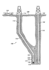
[0022] Figure 1 illustrates an electromagnetic sensor system 100.
Specifically,
Figure 1 shows an electromagnetic sensor system 100 for ranging. As
illustrated, a target
wellbore 102 may extend from a first wellhead 104 into a subterranean
formation 106 from
a surface 108. Generally, target wellbore 102 may include horizontal,
vertical, slanted,
curved, and other types of wellbore geometries and orientations. Target
wellbore 102 may
be cased or uncased. A conductive member 110 may be disposed within target
wellbore
102 and may comprise a metallic material that may be conductive and magnetic.
By way
of example, conductive member 110 may be a casing, liner, tubing, or other
elongated
steel tubular disposed in target wellbore 102. Determining the position and
direction of
target wellbore 102 accurately and efficiently may be required in a variety of
applications.
For example, target wellhore 4 may be a "blowout" well. Target wellbore 102
may need
to be intersected precisely by a second wellbore 112 in order to stop the
"blowout."
Alternatively, it may be desired to avoid collision with target wellbore 102
in drilling
second wellbore 112 or it may be desired to drill the second wellbore parallel
to the target
wellbore 102, for example, in SAGD applications. In examples, target wellbore
102 may
not be accessible and/or information about the position and structure of
target wellbore
102 may not be available. Electromagnetic sensor system 100 may be used for
determining
the location of target wellbore 4 with respect to second wellbore 112.
[0023] With continued reference to Figure 1, second wellbore 112 may also
extend
from a second wellhead 114 that extends into subterranean formation 106 from
surface
108. Generally, second well bore 1 1 2 may include horizontal, vertical,
slanted, curved, and
other types of wellbore geometries and orientations. Additionally, while
target wellbore
102 and second wellbore 112 are illustrated as being land-based, it should be
understood
that the present techniques may also be applicable in offshore applications.
Second
wellbore 112 may be cased or uncased. In examples, a drill string 116 may
begin at second
wellhead 114 and traverse second wellbore 112. A drill bit 118 may be attached
to a distal
end of drill string 116 and may be driven, for example, either by a downhole
motor and/or
CA 03047066 2019-06-13
WO 2018/140058
PCT/US2017/015639
via rotation of drill string 116 from surface 108. Drill bit 118 may be a part
of conductive
body 120 at distal end of drill string 116. While not illustrated, conductive
body 120 may
further comprise one or more of a mud motor, power module, steering module,
telemetry
subassembly, and/or other sensors and instrumentation as will be appreciated
by those of
ordinary skill in the art. As will be appreciated by those of ordinary skill
in the art,
conductive body 120 may be a measurement-while drilling (1\4WD) or logging-
while-
drilling (LWD) system.
[0024] Electromagnetic sensor system 100 may comprise an electromagnetic
induction tool 122. While Figure 1 illustrates usc of electromagnetic
induction tool 122 on
drill string 116, it should be understood that electromagnetic induction tool
122 may be
alternatively used on a wireline. Electromagnetic induction tool 122 may be a
part of
conductive body 120. Electromagnetic induction tool 122 may be used for
determining the
distance and direction to target xvellhore 102. Additionally, electromagnetic
induction tool
122 may be connected to and/or controlled by information handling system 124,
which
may be disposed on surface 108. In examples, information handling system 124
may
communicate with electromagnetic induction tool 122 through a communication
line (not
illustrated) disposed in (or on) drill string 116. In examples, wireless
communication may
be used to transmit information back and forth between information handling
system 124
and electromagnetic induction tool 122. Information handling system 124 may
transmit
information to electromagnetic induction tool 122 and may receive as well as
process
information recorded by electromagnetic induction tool 122. In addition,
electromagnetic
induction tool 122 may include a downhole information handling system 126,
which may
also be disposed on conductive body 120. Processing may be performed at
surface with
information handling system 122, downhole with downhole information handling
system
126, or both at the surface and downhole. Downhole information handling system
126 may
include, but is not limited to, a microprocessor or other suitable circuitry,
for estimating,
receiving and processing signals received by the electromagnetic induction
tool 122.
Downhole information handling system 126 may further include additional
components,
such as memory, input/output devices, interfaces, and the like. While not
illustrated, the
6
CA 03047066 2019-06-13
WO 2018/140058
PCT/US2017/015639
electromagnetic induction tool 122 may include one or more additional
components, such
as analog-to-digital converter, filter and amplifier, among others, that may
be used to
process the measurements of the electromagnetic induction tool 122 before they
may be
transmitted to surface 108. Alternatively, raw measurements from
electromagnetic
induction tool 122 may be transmitted to surface 108.
[0025] In examples, electromagnetic induction tool 122 may comprise
electromagnetic devices such as an electromagnetic source 128 and/or a
receiver 130. It
should be noted that electromagnetic induction tool 122 may comprise a
plurality of
electromagnetic sources 128 and/or a plurality of receivers 130. The plurality
of
electromagnetic sources 128 and the plurality of receivers 130 may be disposed
along a
longitudinal axis of the electromagnetic induction tool 122. The plurality of
electromagnetic sources 128 may include a magnetic source, such as a magnet
assembly
(containing permanent and/or electro- magnetc), eapahle of inducing a
magnetization in
conductive and magnetic member 110 disposed in target wellbore 102.
[0026] Any suitable technique may be used for transmitting signals from
electromagnetic induction tool 122 to surface 108, including, but not limited
to, wired pipe
telemetry, mud-pulse telemetry, acoustic telemetry, and electromagnetic
telemetry. While
not illustrated, conductive body 120 may include a telemetry subassembly that
may
transmit telemetry data to the surface. An electromagnetic source in the
telemetry
subassembly may be operable to generate pressure pulses in the drilling fluid
that
propagate along the fluid stream to surface 108. Al surface 108, pressure
transducers (not
shown) may convert the pressure signal into electrical signals for a digitizer
132. Digitizer
132 may supply a digital form of the telemetry signals to information handling
system 124
via a communication link 134, which may be a wired or wireless link. The
telemetry data
may be analyzed and processed by information handling system 124. For example,
the
telemetry data could be processed to determine location of target wellbore
102. With the
location of target wellbore 102, a driller could control the conductive body
120 while
drilling second wellbore 112 to intentionally intersect target wellbore 102,
avoid target
wellbore 102. and/or drill second wellbore 112 in a path parallel to target
vvellhore 102.
7
CA 03047066 2019-06-13
WO 2018/140058
PCT/US2017/015639
[0027] Conductive body 120 may operate to inject electrical current through
electromagnetic source 128 into subterranean formation 106 for logging,
ranging,
monitoring, and/or measurement purposes. During operation, a significant
current density
may form on the metallic body of conductive body 120, as current prefers
highly-
conductive paths over less conductive ones. Figure 2a illustrates
electromagnetic
induction tool 122, in which electromagnetic source 128, disposed on
conductive body
120 may broadcast an electromagnetic field 200. As illustrated, receiver 130
may record
direct current 202, which may travel along conductive body 120 from
electromagnetic
source 128 to receiver 130. Figure 2b illustrates electromagnetic induction
tool 122 in
which an insulated section 204 may be disposed between electromagnetic source
128
and/or receiver 130. The insulated section 204 may be a gap sub. As
illustrated, insulated
section 204 may alter electromagnetic field 200 and may further prevent direct
current 202
from reaching receiver 130 from electromagnetic source 128. Impedance from
insulated
section 204 may block the most direct route within conductive body 120, thus
direct
current 202 may be prevented from moving further along conductive body 120 and
electromagnetic field 200 may be altered. Figures 3a and 3b illustrate an
additional'
example of electromagnetic induction tool 122, comprising a source electrode
300 and a
receiver electrode 302. Figure 3a may not have an insulated section 204
disposed on
conductive body 120, which may allow for electromagnetic field 200 and direct
current
202 to be recorded by receiver 130. Figure 3b illustrates insulated section
204, which may
be disposed between receiver electrode 302 and receiver 130. Insulated section
204 may
alter electromagnetic field 200 and direct current 202, which may prevent
direct current
202 from reaching receiver 130 and may further distort electromagnetic field
200.
[0028] Insulated section 204 may be disposed near and/or about receiver 130.
For
example, insulated section 204 may be disposed from receivers 130 about one
foot to about
twelve feet, about four feet to about ten feet, about six feet to about eight
feet, and/or about
three feet to about eight feet. Disposing insulated sections 204 near and/or
about receiver
130 may mitigate direct coupling along conductive body 120, may increase gain
and/or
target sensitivity of receiver 130, and may prevent shorting of source-return
current
8
CA 03047066 2019-06-13
WO 2018/140058
PCT/US2017/015639
through conductive body 120. In examples, controlling the impedance within
insulated
section 204 may allow an operator to control electromagnetic field 200 and/or
direct
current 202 in advantageous ways. Impedance control may be performed by
microcontroller 400 and/or changing a geometric property of insulated section
204.
[0029] Figure 4 illustrates an insulated section 204 that may be varied in
real time
to allow for different types of impedance control. Variable impedance may
alter the
overall impedance of insulated section 204, which may alter electromagnetic
field 200
(Referring to Figure 2a) and/or direct current 202 (Referring to Figure 2a).
Adjusting the
variable impedance parameter to a pre-determined value may allow an operator
to
maximize current isolating, and/or eliminate the functionality of insulated
section 204.
Adjusting the variable impedance parameter may be based at least in party from
one or
more previously received signals, which may be recorded by receiver 130
(Referring to
Figure I). Controlling the variable impedance may he performed by an (e.g.
information
handling system 124 or downhole information handling system 126 on Figure 1).
Electromagnetic induction tool 122 may comprise one or more insulated sections
204.
Controlling each insulated section 204 separately and/or interactively with
other insulated
section 204 may produce variable current distributions along conductive body
120. As
illustrated, a microcontroller 400 may control a variable resistor 402, a
variable inductor
404, and/or a variable capacitor 406. In examples, variable resistor 402 may
be a
potentiometer. Microcontroller 400 may be any suitable circuitry to control
insulated
section 204 and may be connected to an information handling system (e.g.,
information
handling system 124 or downhole information handing system 126 on Figure 1).
[0030] Figure 5 illustrates a circuit diagram 500 which may represent a
circuit
model of the current flow through electromagnetic induction tool 122. A gap
sub circuit
502 may represent insulated section 204, in which no current may pass if
activated. A
variable impedance circuit 504 may represented variable impedance control in
which
current may flow through conductive body 120 as controlled by the operator. A
formation
impedance circuit 506 may represent the current flow through subterranean
formation 106,
which may be dictated by the geographical makeup and downhole conditions. Gap
sub
9
CA 03047066 2019-06-13
WO 2018/140058
PCT/US2017/015639
circuit 502 may be an insulators (R = Go), which may block the current path
through
conductive body 120. Thus, the overall impedance becomes a competition between
variable impedance circuit 504 (Rv +1 v) and formation impedance circuit 506
(R + ). To
alter the overall impedance, the variable impedance may be adjusted through
combination
of variable resistor (Rv), inductor (Lv), and capacitor (Cv) connecting in
series as
illustrated in Figure 6 and/or in parallel as illustrated in Figure 7. When
they are in series,
the overall impedance of insulated section 204 impedance may be expressed as
seen
below:
-
¨ _________________________________________
¨
e:
(1)
where w is the radial frequency. For parallel RLC, the overall impedance of
insulated section 204 may be expressed as:
- ____________________________________
-
(2)
[0031] By adjusting values of , L, , and C, an operator may be able to
synthetically produce different impedances. Figure 8 illustrates an example of
a RLC
circuit which may adjust the impedance of insulated section 204. In this
example,
subterranean formation l 06 may have an impedance of 20 1- j124.87 ohms which
may be
CA 03047066 2019-06-13
WO 2018/140058
PCT/US2017/015639
input into formation impedance circuit 506. The resistance and inductance of
the load may
be fixed at 5 ohms and 1 H, respectively, within variable impedance circuit
504. Figure
9 illustrates a graph using the variable of variable impedance circuit 504 and
formation
impedance circuit 506 and further illustrates the change of how impedance
magnitude
changes with different capacitance for various operating frequencies.
[0032] Figure 10 illustrates a flow chart of varying impedance within
insulated
section 204 (Referring to Figure 2) for different purposes. Microcontroller
400 (Referring
to Figure 4) may maximize current isolation 1000 on two sides of insulated
section 204 by
maximizing , Li), and C0. Maximizing the current isolation between the two
sides of
insulated section 204 may be accomplished by maximizing the overall impedance
of
insulated section 204. An approach may be to find the derivative of
expressions (1) and
(2) above with respect to Rv Lv Cv jointly and may set each variable to
substantially zero
impedance to solve for the relation between Rv, Lv, and Cv. Referring to
Figure 0, the
impedance magnitude may have a bell shape curve, where the maximum current
isolation
at 2 kIlz happens when = 0.56 F. However at a different frequency, this value
may
change. Therefore, in order to find the global maximum, the derivative of
expressions (1)
and (2) may need to be computed with respect to frequency. In practice, well-
logging tools
may not operate in a higher kHz frequency range, the capacitance Cv may
dominate,
therefore an operator may omit the impact of Lv when adjusting impedance for
maximum
current isolation. Functions may comprise a base measurement 1002 with
insulated
section 204, which may be found by setting R, to the highest possible value
and an
eliminating gap sub step 1004 for measurements may be found by setting Z, to
0.
[0033] In examples, impedance control of insulated section 204 may provide
additional measurements for an inversion process. The inversion process may be
utilized
to calculated downhole electromagnetic parameters. Different impedance of
insulated
section 204 may alter the current distribution differently, each variation may
provide a
distinct set of measurements at receivers 130 (Referring to Figure 1). There
may be a set
number of impedance combinations among all insulated sections 204 (Referring
to Figure
2) in electromagnetic induction tool 122 (Referring to Figure 1). The
disclosure provides
11
CA 03047066 2019-06-13
WO 2018/140058
PCT/US2017/015639
a variety of methods through varying impedance to obtain any number of
measurements
to work with as opposed to just one without impedance control, in which
adequate forward
models may be available for modeling electromagnetic induction tool 122 with
insulated
sections 204.
[0034] In examples, an intelligent feedback system 1100, as illustrated in
Figure
11, may take a first measurement from receivers 130 (Referring to Figure 1) as
feedback
to control the impedance parameter within insulated sections 204 (Referring to
Figure 2),
which may produce controlled current distribution within electromagnetic
induction tool
122 (Referring to Figure 1). A second measurement from receivers 130 may be
taken and
the process repeated. Any number of measurements may be performed. As
illustrated,
electromagnetic induction tool 122 may comprise electromagnetic source 128,
source
electrode 300 (Referring to Figure 3) and receiver electrode 302 (Referring to
Figure 3).
Intelligent feedback system 1100 may operate in real time as impedance on
insulated
section 204 may be adjusted accordingly to fit a selected operation by an
operator. In
examples, recorded voltage measurements in intelligent feedback system 1100
may be fed
to microcontroller 400 for processing and interpretation. For example, the
first
measurement and second measurement may be utilized in an inversion process.
Any
number of measurements may be utilized for the inversion process. The
inversion process
may be able to calculate downhole electromagnetic parameters. In examples, the
first
measurement and the second measurement may be performed with substantially
zero
impedance or effectively infinite impedance, which may help in inversion
calculations.
Calculated downhole electromagnetic parameters may lead to adjusting
operational
parameters in well operations. Well operations may comprise logging, ranging,
monitoring, and/or measurement of the subterranean formation. In examples,
microcontroller 400 (Referring to Figure 4) may be able to determine if
voltages stay
relatively unchanged across time due to strong direct current 202 (Referring
to Figure 2)
from source electrode 300 and receiver electrode 302. Microcontroller 400 may
alter the
impedance within each insulated section 204 and maximize current isolation,
hindering
12
CA 03047066 2019-06-13
WO 2018/140058
PCT/US2017/015639
direct current 202, which may allow for intelligent feedback system 1100 to
recorded
weaker signals from target wellbore 102 (Referring to Figure 1).
[0035] In some embodiments, electromagnetic sensor system 100 may be
incorporated into a conveyance system 1200. Figure 2 illustrates a conveyance
system
1200. As illustrated, wellbore 102 (Referring to Figure 1) may extend from
wellhead 102
into subterranean formation 106 from surface 108. Generally, wellbore 102 may
include
horizontal, vertical, slanted, curved, and other types of wellbore geometries
and
orientations. Wellbore 102 may comprise a metallic member 202. Conductive
member I 10
may be disposed within wellbore 102 and may comprise a metallic material that
may be
conductive and magnetic. By way of example, conductive member 110 may be a
casing,
liner, tubing, or other elongated steel tubular disposed in wellbore 102.
Properties of
subterranean formation 106 may be determined by conveyance system 1200 from
within
wellbore 102.
[0036] Conveyance system 1200 may be supported by derrick 1202 at surface 108.
Conveyance system 1200 may be tethered to vehicle 1204 through conveyance
1206.
Conveyance 1206 may be disposed around one or more sheave wheels 1208. Derrick
1202
may include a load cell (not shown) which determines the amount of pull on
conveyance
1206 at surface 108. Information handling system 124 may control a safety
valve (not
illustrated) which controls the hydraulic pressure that drives drum 1210 on
vehicle 1204,
which may reel up and/or release conveyance 1206 which may move
electromagnetic
induction tool 122 up and/or down. The safety valve may be adjusted to a
pressure such
that sheave wheel 1208 may only impart a small amount of tension to conveyance
1206
and/or over and above the tension necessary to retrieve conveyance 1206 and/or
electromagnetic induction tool 122..1 he safety valve is typically set a few
hundred pounds
above the amount of desired safe pull on conveyance 1206 such that once that
limit is
exceeded, further pull on conveyance 1206 may be prevented.
[0037] Conveyance 1206 may individually be a wireline, slickline, coiled
tubing,
pipe, or the like, which may provide mechanical suspension as well as
electrical
conductivity for electromagnetic induction tool 122. Where it may provide
electrical
conducting, conveyance 1206 may comprise an inner core of a plurality of
electrical
13
CA 03047066 2019-06-13
WO 2018/140058
PCT/US2017/015639
conductors covered by an insulating wrap. An inner and outer steel armor
sheath may be
disposed around the conductors. The electrical conductors may be used for
communicating
power and telemetry between vehicle 1204 (or other equipment) and
electromagnetic
induction tool 122.
[0038] This systems and methods may include any of the various features of the
compositions, methods, and system disclosed herein, including one or more of
the
following statements.
[0039] Statement 1: A method comprising: introducing an electromagnetic
induction tool into a wellbore, wherein the electromagnetic induction tool
comprises: an
insulated section; an electromagnetic device disposed within about 15 feet of
the insulated
section, wherein the electromagnetic device comprises at least one device
selected from
the group consisting of an electromagnetic source and a receiver; performing a
first
meaciirement with the electromagnetic induction tool; adjusting an impedance
parameter
of the insulated section; performing a second measurement with the
electromagnetic
induction tool; including the first measurement and the second measurement in
an
inversion process, wherein the inversion process calculates the downhole
electromagnetic
parameters; and adjusting at least one operational parameter of a well
operation based at
least in part on the downhole electromagnetic parameters.
[0040] Statement 2: The method of statement 1, wherein the electromagnetic
source is disposed on the electromagnetic induction tool, and the receiver is
disposed on
the electromagnetic induction tool, wherein the electromagnetic source and the
receiver
are individually spaced from the insulated section a distance that is less
than 3 feet from
the electromagnetic source or the receiver.
[0041] Statement 3: The method of statement I or 2, wherein the insulated
section
is a gap sub.
[0042] Statement 4: The method of any preceding statement, wherein the
insulated
section is a gap sub and wherein adjusting the impedance parameter comprises
adjusting
the impedance parameter electrically with at least one of a potentiometer,
variable
capacitor, or variable inductor.
14
CA 03047066 2019-06-13
WO 2018/140058
PCT/US2017/015639
[0043] Statement 5: The method of any preceding statement, wherein adjusting
the
impedance parameter comprises adjusting the impedance parameter mechanically
by
changing a geometric property of a component of the insulated section.
[0044] Statement 6: The method of any preceding statement, wherein the
impedance parameter is at least in part resistive and wherein the impedance
parameter is
at least in part inductive.
[0045] Statement 7: The method of any preceding statement, wherein the
impedance parameter is at least in part capacitive and wherein adjusting the
impedance
parameter comprises adjusting the impedance parameter with a microcontroller
and
wherein adjusting the impedance parameter is at least in part a function of
formation
impedance.
[0046] Statement 8: The method of any preceding statement, wherein the
electromagnetic source or the receiver comprises an electrode or a coil.
[0047] Statement 9: The method of any preceding statement, wherein the first
measurement or the second measurement is performed with a substantially zero
impedance
and wherein the first measurement or the second measurement is performed with
an
effectively infinite impedance
[0048] Statement 10: The method of any preceding statement, wherein adjusting
the impedance parameter comprises adjusting a gap sub impedance to be about a
formation
impedance.
[0049] Statement 11: The method of any preceding statement, wherein the
electromagnetic tool further comprises disposing a second insulated section
within about
15 feet of the electromagnetic device, wherein the method further comprises
adjusting an
impedance parameter of the second insulated section and wherein the performing
the
second measurement is performed after the impedance parameter of the insulated
section
and the impedance parameter of the second insulated section arc adjusted.
[0050] Statement 12: The method of any preceding statement, further comprising
performing a third measurement after the impedance parameter of the second
insulated
section is adjusted and after the second measurement is performed, wherein the
third
measurement is implemented in the inversion process.
CA 03047066 2019-06-13
WO 2018/140058
PCT/US2017/015639
[0051] Statement 13: The method of any preceding statement, wherein the
impedance parameter is adjusted to a pre-determined value.
[0052] Statement 14: The method of any preceding statement, wherein the
impedance parameter is adjusted based at least in part on one or more
previously received
signals.
[0053] Statement 15: The method of any preceding statement, wherein the well
operation is a drilling, logging, production, or completion operation_
[0054] Statement 16: An electromagnetic sensor system, comprising: a
conductive body, wherein the conductive body comprises an insulated section;
an
electromagnetic device disposed within about 15 feet of the insulated section,
wherein the
electromagnetic device comprises at least one device selected from the group
consisting
of a electromagnetic source and a receiver; and a microcontroller configured
to adjust an
impedance parameter of the insulated section.
[0055] Statement 17: The electromagnetic sensor system of statement 1b,
further
comprising a receiver disposed on the downhole tool, wherein the
electromagnetic source
and the receiver are individually spaced from the insulated section a distance
that is less
than 3 feet between the electromagnetic source and the receiver.
[0056] Statement 18: The electromagnetic sensor system of statement 16 or
statement 17, wherein the insulated section is a gap sub.
[0057] Statement 19: The electromagnetic sensor system of any preceding
statement, further comprising a potentiometer, a variable capacitor, or a
variable inductor.
[0058] Statement 20: The electromagnetic sensor system of any preceding
statement, wherein the electromagnetic source or the receiver comprises an
electrode or a
coil.
[0059] The preceding description provides various examples of the systems and
methods of use disclosed herein which may contain different method steps and
alternative
combinations of components. It should be understood that, although individual
examples
may be discussed herein, the present disclosure covers all combinations of the
disclosed
examples, including, without limitation, the different component combinations,
method
step combinations, and properties of the system. It should be understood that
the
compositions and methods are described in terms of "comprising," "containing,"
or
16
"including" various components or steps, the compositions and methods can also
"consist
essentially of" or "consist of" the various components and steps. Moreover,
the indefinite articles
"a" or "an," as used in the claims, are defined herein to mean one or more
than one of the
element that it introduces.
[0060] For the sake of brevity, only certain ranges are explicitly disclosed
herein.
However, ranges from any lower limit may be combined with any upper limit to
recite a range
not explicitly recited, as well as, ranges from any lower limit may be
combined with any other
lower limit to recite a range not explicitly recited, in the same way, ranges
from any upper limit
may be combined with any other upper limit to recite a range not explicitly
recited.
Additionally, whenever a numerical range with a lower limit and an upper limit
is disclosed, any
number and any included range falling within the range are specifically
disclosed. In particular,
every range of values (of the form, "from about a to about b," or,
equivalently, "from
approximately a to b," or, equivalently, "from approximately a-b") disclosed
herein is to be
understood to set forth every number and range encompassed within the broader
range of values
even if not explicitly recited. Thus, every point or individual value may
serve as its own lower
or upper limit combined with any other point or individual value or any other
lower or upper
limit, to recite a range not explicitly recited.
[0061] Therefore, the present examples are well adapted to attain the ends and
advantages mentioned as well as those that are inherent therein. The
particular examples
disclosed above are illustrative only, and may be modified and practiced in
different but
equivalent manners apparent to those skilled in the art having the benefit of
the teachings herein.
Although individual examples are discussed, the disclosure covers all
combinations of all of the
examples. Furthermore, no limitations are intended to the details of
construction or design
herein shown, other than as described in the claims below. Also, the terms in
the claims have
their plain, ordinary meaning unless otherwise explicitly and clearly defined
by the patentee. It
is therefore evident that the particular illustrative examples disclosed above
may be altered or
modified and all such variations are considered within the scope and spirit of
those examples. If
there is any conflict in the usages of a word or term in this specification
and one or more
patent(s) or other documents that may be herein referred to, the definitions
that are consistent
with this specification should be adopted.
17
Date Recue/Date Received 2021-09-29