Note: Descriptions are shown in the official language in which they were submitted.
CA 03047281 2019-06-14
WO 2018/111956 PCT/US2017/065950
SYSTEM AND METHOD CONFIGURED TO PROVIDE
EXTRACORPOREAL SUPPORT FOR PREMATURE FETUS
CROSS REFERENCE TO RELATED APPLICATIONS
[0001] This application claims benefit to U.S. Provisional Application No.
62/434,100
filed December 14, 2016, the disclosure of which is hereby incorporated by
reference in its
entirety.
TECHNICAL FIELD
[0002] The present disclosure relates generally to neonatal care. More
specifically, the
present disclosure describes devices, systems, and methods related to
improving the viability of a
premature fetus outside of the womb. According to one aspect, the present
disclosure relates to
improving viability of premature fetuses at a stage of development prior to 28
weeks gestation.
BACKGROUND
[0003] Extreme prematurity is the leading cause of infant morbidity and
mortality in
the United States, with over one third of all infant deaths and one half of
cerebral palsy diagnoses
attributed to prematurity. The 2010 Center for Disease Control National Vital
Statistics Report
notes birth rates at a gestational age of less than 28 weeks in the United
States over roughly the
past decade have remained stable at approximately 0.7%, or 30,000 births
annually. Similarly,
birth rates at gestational ages 28-32 weeks over the past decade in the United
States have been
stable at 1.2%, or 50,000 births annually.
[0004] Premature birth may occur due to any one of a multitude of reasons. For
example, premature birth may occur spontaneously due to preterm rupture of the
membranes
(PROM), structural uterine features such as shortened cervix, secondary to
traumatic or
infectious stimuli, or due to multiple gestation. Preterm labor and delivery
is also frequently
encountered in the context of fetoscopy or fetal surgery, where
instrumentation of the uterus
often stimulates uncontrolled labor despite maximal tocolytic therapy.
[0005] Respiratory failure represents the most common and challenging problem
associated with extreme prematurity, as gas exchange in critically preterm
neonates is impaired
by structural and functional immaturity of the lungs. Advances in neonatal
intensive care have
achieved improved survival and pushed the limits of viability of preterm
neonates to 22 to 24
weeks gestation, which marks the transition from the canalicular to the
saccular phase of lung
development. Although survival has become possible, there is still a high rate
of chronic lung
- 1 -
CA 03047281 2019-06-14
WO 2018/111956 PCT/US2017/065950
disease and other complications of organ immaturity, particularly in fetuses
born prior to 28
weeks gestation. The development of a system that could support normal fetal
growth and organ
maturation for even a few weeks could significantly reduce the morbidity and
mortality of
extreme prematurity, and improve quality of life in survivors.
[0006] The development of an "artificial placenta" has been the subject of
investigation
for over 50 years with little success. Previous attempts to achieve adequate
oxygenation of the
fetus in animal models have employed traditional extracorporeal membrane
oxygenation
(ECMO) with pump support, and have been limited by circulatory overload and
cardiac failure in
treated animals. The known systems have suffered from unacceptable
complications, including:
1) progressive circulatory failure due to after-load or pre-load imbalance
imposed on the fetal
heart by oxygenator resistance or by circuits incorporating various pumps; and
2) contamination
and fetal sepsis.
[0007] Accordingly, a system and method configured to provide extracorporeal
support
for a premature fetus, or fetuses (preterm or term) with inadequate
respiratory gas exchange to
support life, due to a spectrum of conditions/disorders, may improve
viability.
SUMMARY
[0008] According to one aspect of the disclosure, a chamber configured to
enclose a
fetus within an interior space of the chamber is disclosed. The chamber
includes a housing
including a first shell and a second shell, the first shell and the second
shell cooperate to at least
partially define the interior space, the housing configured such that the
second shell is movable
with respect to the first shell from a first position to a second position,
such that in the first
position the chamber is in an open configuration, and in the second position
the chamber is in a
closed configuration. The chamber further includes a stop assembly including a
clamp and an
actuator, the clamp positioned in the interior space when the housing is in
the closed
configuration, the actuator coupled to the clamp such that movement of the
actuator moves the
clamp, the actuator positioned at least partially outside the interior space
when the housing is in
the closed configuration. When the chamber is in the open configuration the
first shell and the
second shell cooperatively define an opening into the interior space, the
opening defines a first
distance measured from a portion of the first shell to a portion of the second
shell, when the
chamber is in the closed configuration the opening defines a second distance
measured from the
portion of the first shell to the portion of the second shell, and the second
distance is less than the
first distance.
- 2 -
CA 03047281 2019-06-14
WO 2018/111956 PCT/US2017/065950
[0009] According to another aspect of the disclosure, a chamber configured to
enclose a
fetus within an interior space of the chamber is disclosed. The chamber
includes an outer wall
that defines an outer boundary of the interior space, an inner wall that
extends from the outer
wall into the interior space such that the inner wall partially defines both a
first portion of the
interior space and a second portion of the interior space, a clamp positioned
within the second
portion, the clamp movable in a direction from one of the outer wall and the
inner wall toward
the other of the outer wall and the inner wall, and an actuator operably
coupled to the clamp such
that movement of the actuator moves the clamp in the direction.
[0010] According to another aspect of the disclosure, a system configured to
provide
oxygen to a fetus is disclosed. The system includes a cart including a housing
that defines a
housing interior space, a chamber defining a chamber interior space that is
sized to receive the
fetus, a first fluid circuit including a container of a liquid, a pump
configured to move the liquid
from the source to the chamber, the pump further configured to move the liquid
from the
chamber to a reservoir, a second fluid circuit including an oxygenator
configured to transfer
oxygen to the fetus. The system defines a first configuration in which both
the chamber and the
oxygenator are positioned outside of the housing interior space, and the
chamber is disconnected
from the first fluid circuit, and the system defines a second configuration in
which both the
chamber and the oxygenator are positioned within the housing interior space,
and the chamber is
in fluid connection with the first fluid circuit.
BRIEF DESCRIPTION OF THE DRAWINGS
[0011] The foregoing summary, as well as the following detailed description of
illustrative embodiments of the application, will be better understood when
read in conjunction
with the appended drawings. For the purposes of illustrating the present
disclosure, there is
shown in the drawings illustrative embodiments. It should be understood,
however, that the
application is not limited to the specific embodiments and methods disclosed,
and reference is
made to the claims for that purpose. In the drawings:
[0012] Fig. 1 is a first isometric view of an extracorporeal support system
according to
one embodiment, the extracorporeal support system in a first configuration;
[0013] Fig. 2 is a second isometric view of the extracorporeal support system
illustrated
in Fig. 1, the extracorporeal support system in the first configuration;
[0014] Fig. 3 is a third isometric view of a portion of the extracorporeal
support system
illustrated in Fig. 1, the extracorporeal support system in the first
configuration;
- 3 -
CA 03047281 2019-06-14
WO 2018/111956 PCT/US2017/065950
[0015] Fig. 4 is an isometric view of the extracorporeal support system
illustrated in
Fig. 1, the extracorporeal support system in a second configuration;
[0016] Fig. 5 is an isometric view of a fetal chamber of the extracorporeal
support
system according to one embodiment, the fetal chamber in a first
configuration;
[0017] Fig. 6 is a top plan view of the fetal chamber illustrated in Fig. 5,
the fetal
chamber in a second configuration;
[0018] Fig. 7 is a top plan view of a first member of a volume adjustment
assembly;
[0019] Fig. 8 is a top plan view of a second member of a volume adjustment
assembly;
[0020] Fig. 9 is a top plan view of a third member of a volume adjustment
assembly;
[0021] Fig. 10 is a schematic view of the extracorporeal support system
illustrated in
Fig. 1, in use in an operating room;
[0022] Fig. 11 is an isometric view of a portion of the fetal chamber
illustrated in Fig.
5, the portion including an emergency clamp assembly, the emergency clamp
assembly is a first
configuration;
[0023] Fig. 12 is an isometric view of a portion of the fetal chamber
illustrated in Fig.
5, the portion including the emergency clamp assembly in a second
configuration;
[0024] Fig. 13 is an isometric view of a seal of the fetal chamber according
to one
aspect of the disclosure;
[0025] Fig. 14 is a cross-sectional view of the fetal chamber illustrated in
Fig. 5 along
line 14-14, the fetal chamber including a port;
[0026] Fig. 15 is an isometric view of the port illustrated in Fig. 14,
according to one
embodiment, in a first configuration;
[0027] Fig. 16 is a cross-sectional view of the port illustrated in Fig. 15 in
the first
configuration;
[0028] Fig. 17 is a cross-sectional view of the port illustrated in Fig. 15 in
a second
configuration;
[0029] Fig. 18 is a cross-sectional view of the port illustrated in Fig. 15 in
the second
configuration, and a suction device;
[0030] Fig. 19 is a cross-sectional view of a port of the extra corporeal
support system,
according to another embodiment;
[0031] Fig. 20 is a cross-sectional view of the port illustrated in Fig. 19,
and a suction
device, the suction device in a first position;
[0032] Fig. 21 is a cross-sectional view of the port and suction device
illustrated in Fig.
20, the section device in a second position;
- 4 -
CA 03047281 2019-06-14
WO 2018/111956 PCT/US2017/065950
[0033] Fig. 22 is a cross-sectional view of the port and suction device
illustrated in Fig.
20, the section device in a third position;
[0034] Fig 23 is an isometric view of a port of the extra corporeal support
system,
according to another embodiment;
[0035] Fig. 24 is a side cross-sectional view of the port illustrated in Fig
23 and a
suction device in a first position relative to the port;
[0036] Fig. 25 is a side cross-sectional view of the port and the suction
device
illustrated in Fig 25, the suction device in a second position relative to the
port;
[0037] Fig. 26 is a side cross-sectional view of the port and the suction
device
illustrated in Fig 25, the suction device in a third position relative to the
port;
[0038] Fig. 27 is a schematic view of a first fluid circuit of the
extracorporeal support
system illustrated in Fig. 1;
[0039] Fig. 28 is an isometric view of a pressure regulator of the first fluid
circuit
illustrated in Fig. 27;
[0040] Fig. 29 is an isometric view of a sterilization unit of the
extracorporeal support
system illustrated in Fig. 1, the sterilization unit in a first configuration;
[0041] Fig. 30 is an isometric view of the sterilization unit illustrated in
Fig. 29, the
sterilization unit in a second configuration; and
[0042] Fig. 31 is a schematic view of a second fluid circuit of the
extracorporeal
support system illustrated in Fig. 1.
DETAILED DESCRIPTION OF ILLUSTRATIVE EMBODIMENTS
[0043] Aspects of the disclosure will now be described in detail with
reference to the
drawings, wherein like reference numbers refer to like elements throughout,
unless specified
otherwise. Certain terminology is used in the following description for
convenience only and is
not limiting. The term "plurality", as used herein, means more than one. The
terms "a portion"
and "at least a portion" of a structure include the entirety of the structure.
Certain features of the
disclosure which are described herein in the context of separate embodiments
may also be
provided in combination in a single embodiment. Conversely, various features
of the disclosure
that are described in the context of a single embodiment may also be provided
separately or in
any subcombination.
[0044] Referring to Figs. 1 to 4, a system 10 is configured to provide
extracorporeal
support to a premature fetus. According to one aspect of the disclosure the
system 10 is
configured to provide a system environment that is similar to an environment
the premature fetus
- 5 -
CA 03047281 2019-06-14
WO 2018/111956 PCT/US2017/065950
would experience in utero. Viability of a premature fetus that is removed from
the uterine
environment and that is, for example, between about 22 weeks to about 24 weeks
gestation, may
be increased by placing the premature fetus in the system environment.
According to one aspect
of the disclosure, the system environment is configured to: 1) limit exposure
of the premature
fetus to light; 2) limit exposure of the premature fetus to sound; 3) maintain
the fetus submerged
within a liquid environment; 4) maintain the premature fetus within a desired
temperature range;
or 5) any combination thereof
[0045] The system 10 includes a cart 12 having a frame 18 and a housing 20.
The
frame 18 is configured to support the housing 20 such that the housing 20 is
configured to at
least partially contribute to providing the system environment to the
premature fetus. The
housing 20 includes one or more housing members 22 that at least partially
define an interior
space 24 that contains the system environment. As shown in the illustrated
embodiment, the
housing members 22 may include a plurality of side walls 26, a lid 28, and a
base 30. According
to one aspect of the disclosure, at least one of the plurality of side walls
26, the lid 28, or both are
moveable.
[0046] The housing 20 defines a first configuration, an example of which is
shown in
Figs. 1, 2, and 3, in which the plurality of side walls 26 and the lid 28 are
arranged to
cooperatively define the interior space 24. In the first configuration the
housing 20 is configured
to maintain the system environment and restrict access to the interior space
24. The housing 20
defines a second configuration, an example of which is shown in Fig. 4, in
which the plurality of
side walls 26 and the lid 28 are arranged to provide increased access to the
interior space 24.
[0047] As shown in the illustrated embodiment, the housing 20 may include four
side
walls 26. One or more of the side walls 26, for example all four, three, two,
or one of the side
walls 26, may be pivotally coupled to the frame 18. As shown in Figs. 1, 2,
and 3, in the first
configuration the side walls 26, the lid 28, and the base 30 cooperate to
define the interior space
24. As shown in Fig. 4, in the second configuration one or more of the side
walls 26 are pivoted
away from others of the side walls 26 such that the interior space 24 is
accessible from an
exterior of the system 10. The housing 20 may include a locking mechanism 32
configured to:
1) secure the side walls 26 in the first configuration when the locking
mechanism 32 is engaged,
and 2) allow the side walls 26 to pivot when the locking mechanism 32 is
disengaged.
[0048] As shown in the illustrated embodiment, the locking mechanism 32 may
include
corresponding members located on adjacent ones of the plurality of side walls
26. For example
the locking mechanism may include a latch 33a located on one of the side walls
26 and a
- 6 -
CA 03047281 2019-06-14
WO 2018/111956 PCT/US2017/065950
projection 33b configured to be captured by the latch 33a thereby securing the
adjacent ones of
the plurality of side walls 26 to one another.
[0049] As shown in the illustrated embodiment, the lid 28 may be translatable
with
respect to the side walls 26. The system 10 may be configured such that the
lid 28 is translatable
along a vertical direction, which is substantially perpendicular to a surface
upon which the
system 10 is positioned, for example a floor, such as a hospital floor.
According to one aspect of
the disclosure, in the first configuration the lid 28 is in close proximity,
for example touching,
one or more of the side walls 26, and in the second configuration an entirety
of the lid 28 is
spaced from the floor a distance of at least about six feet, for example about
seventy-one inches.
The system 10 may be further configured such that when the entirety of the lid
28 is spaced from
the floor by a distance of at least about six feet, an entirety of the system
10 is positioned less
than seventy-nine inches from the floor.
[0050] The amount of clearance under the lid 28 is configured to allow a
maximum
amount of space for a person, such as a doctor or nurse, to access the system
10 without
interference from the lid 28, and the maximum height of the system 10 is
configured to allow the
system 10 to pass through a standard size hospital doorway. According to
another aspect of the
disclosure, in the second configuration an entirety of the lid 28 may be
spaced from the floor a
distance less than six feet, a portion of the system 10 may be spaced from the
floor by a distance
greater than seventy-nine inches, or both.
[0051] According to another embodiment, the side walls 26 and the lid 28 may
be an
integral or monolithic piece. According to another embodiment, the side walls
26 and the lid 28,
whether separate or monolithic, may be translatable, pivotable, or both
relative to the frame 18.
[0052] The lid 28 may be transparent such that a person outside of the system
10 can
view the interior space 24 of the system 10 when the housing 20 is in the
first configuration. The
housing 20 may further include a removable, opaque cover 34 that prevents
light from a source
outside of the interior space 24 from reaching the interior space 24 through
the transparent lid 28.
The system 10 may be configured to limit the amount of light that reaches the
interior space 24
when the system 10 is in the first configuration to about 1.2 lux or below.
According to one
embodiment, the opaque cover 34 may be secured to the housing 20 magnetically.
Alternatively,
the lid 28 may be opaque. The system 10 may be configured to provide an
indirect view of the
interior space 24, for example the system 10 may include a camera positioned
inside the interior
space 24 that transmits an image to a screen outside the interior space 24.
[0053] The housing 20 may be configured such that the lid 28 remains in the
second
configuration without a person exerting an external force on the lid 28. For
example, the housing
- 7 -
CA 03047281 2019-06-14
WO 2018/111956 PCT/US2017/065950
20 may include a constant force spring assembly that provides a retention
force that holds the lid
28 at its current distance from the floor until an external force, in addition
to the force of gravity,
is applied to the lid 28.
[0054] The housing 20 may be configured to provide access to the interior
space 24
when the housing 20 is in the first configuration. As shown in the illustrated
embodiment, the
housing 20 includes one or more access ports 36 that are each configured to
provide a
passageway for a person's hand from an exterior of the system 10 to the
interior space 24. The
access ports 36 may each include a respective cover 38 configured to block the
access port 36.
Each of the respective covers 38 may be configured to be moved relative to the
access port 36
thereby providing access to the passageway. The access port 36 may include a
flexible iris 40
configured to provide a seal around an arm of the person using the access port
36 to access the
interior space 24.
[0055] According to one aspect of the disclosure, the access ports 36 are
positioned
such that a portion of the access port 36 is between about 3 feet and about 4
feet from the floor.
For example, a center of the access port 36 may be positioned about forty-
three inches from the
floor. The access ports 36 may be positioned such that different ones of the
access ports 36
provide access to the interior space 24 along different directions. As shown
in the illustrated
embodiment, the system 10 may include: a first one of the access ports 36a
configured to provide
access to the interior space 24 along a first direction; a second one of the
access ports 36b
configured to provide access to the interior space 24 along a second direction
that is opposite the
first direction; a third one of the access ports 36c configured to provide
access to the interior
space 24 along a third direction that is perpendicular to both the first
direction and the second
direction, or any combination thereof
[0056] The system 10, according to one embodiment, may include a heater 42
configured to maintain the interior space 24 within a desired temperature
range. For example,
the heater 42 may be configured to maintain a temperature within the interior
space 24 between
about twenty-eight degrees Celsius and about thirty-eight degrees Celsius,
preferably between
about thirty degrees Celsius and about thirty-four degrees Celsius, for
example about thirty-two
degrees Celsius. The system 10 according to one embodiment, may include a
sound dampening
system configured to dampen the amplitude of sound that reaches the interior
space 24 of the
system 10 when the housing is in the first configuration to below about 20
decibels. According
to one embodiment, the sound dampening can be achieved by attaching sound
dampening
material to one or more of the side walls 26.
- 8 -
CA 03047281 2019-06-14
WO 2018/111956 PCT/US2017/065950
[0057] The system 10 may be mobile such that system is configured to be
moveable
from one location to another while still providing appropriate levels of
oxygen delivery to the
interior space 24, for example to a fetus in the interior space 24. According
to one aspect of the
disclosure, the system 10 may include a plurality of wheels 23 enabling the
system 10 to be
moved, for example from an operating room to a neonatal intensive care unit.
As shown in the
illustrated embodiment, the wheels 23 are coupled to the cart 12.
[0058] Referring to Figs. 5 and 6, the system 10 includes a chamber 100
configured to
receive and enclose a fetus 2, for example a premature, human fetus, within an
extra uterine,
enclosed environment. According to one aspect of the disclosure, the cart 12
is configured to
enclose the chamber 100 within the interior space 24. The chamber 100 defines
a chamber
interior space 102 that contains the extra uterine, enclosed environment. The
chamber 100
defines a first configuration, also referred to herein as an open
configuration, as shown in Fig. 6.
In the open configuration the chamber interior space 102 is accessible such
that the chamber
interior space 102 is configured to receive the fetus 2. The chamber 100
defines a second
configuration, also referred to herein as a closed configuration, as shown in
Fig. 5. In the closed
configuration the chamber interior space 102 is sealed off from the
environment surrounding the
chamber 100.
[0059] The chamber 100 includes a chamber housing 104 that defines the chamber
interior space 102. According to one aspect of the disclosure, the chamber
housing 104 may
include an outer chamber wall 106 that defines an outer boundary of the
chamber interior space
102. As shown in the illustrated embodiment, the outer chamber wall 106
defines an outer
perimeter of the chamber 100 when the chamber 100 is in the closed
configuration. The
chamber housing 104 may further include an inner chamber wall 108 that at
least partially
separates a first portion 110 of the chamber interior space 102 from a second
portion 112 of the
chamber interior space 102.
[0060] According to one aspect of the disclosure, when the chamber 100 is in
the open
configuration a first shell 114 of the housing and a second shell 116 of the
housing cooperatively
define an opening 117 into the interior chamber space 102, the opening 117
defines a first
distance D1 measured from a portion 114a of the first shell 114 to a portion
116a of the second
shell 116. When the chamber 100 is in the closed configuration the opening 117
defines a
second distance D2 measured from the portion 114a of the first shell 114 to
the portion 116a of
the second shell 116. The second distance D2 is less than the first distance
Dl. As shown in the
illustrated embodiment, the second distance D2 may be zero such that the
portion 114a and the
portion 116a abut. According to another embodiment D2 may be greater than
zero.
- 9 -
CA 03047281 2019-06-14
WO 2018/111956 PCT/US2017/065950
[0061] The system 10 may be configured such that the chamber 100 is rotatable
about
an axis 101, relative to the cart 12. The axis 101 may be a longitudinal axis
that the chamber 100
is elongate along. As shown in the illustrated embodiment, the axis 101 may
pass through a first
end 180 of the chamber 100 and a second end 182 of the chamber 100. According
to one
embodiment, the chamber 100 is rotatable about the axis 101 through a full
revolution of 360
degrees. According to another embodiment, the chamber 100 is rotatable about
the axis 101
through less than a full revolution of 360 degrees. For example, the chamber
100 may be
rotatable about the axis 101 about 180 degrees clockwise from the position
shown in Fig. 6, and
rotatable about 180 degrees counterclockwise from the position shown in Fig.
6. The system 10
being configured such that the chamber 100 is rotatable about the axis 101
relative to the cart 12
allows the position of the fetus 2 to be adjusted while maintaining the
chamber 100 in the closed
configuration. Adjustment of the position of the fetus 2 may reduce or
eliminate dependent
edema, fetal asymmetry, pressure sores, or other undesired conditions.
[0062] The chamber 100 defines a length measured along the axis 101, a width
measured along a lateral direction perpendicular to the axis 101, and a height
measured along a
vertical direction that is perpendicular to both the axis 101 and the lateral
direction. According
to one embodiment, the chamber 100 defines a maximum length measured along the
axis 101, a
maximum width measured along a line that is perpendicular to the axis 101 and
that intersects
the first shell 114 in two separate locations, and a maximum height measured
along a line that is
perpendicular to both the axis 101 and the lateral direction and that
intersects both the first shell
114 and the second shell 116 when the chamber 100 is in the closed
configuration. As shown in
the illustrated embodiment, the chamber 100 may be configured such that the
maximum length is
greater than the maximum width, and the maximum width is greater than the
maximum height.
[0063] The chamber 100 may include a volume adjustment assembly 210 configured
to
change, for example increase, decrease, or both, a volume defined by the
interior space 102 when
the chamber 100 is in the closed configuration. The chamber 100 may include at
least one
flexible wall 212. As shown in the illustrated embodiment, the first shell 114
may include a first
flexible wall 212a and the second shell 116 may include a second flexible wall
212b. The
volume adjustment assembly 210 may include a member 214 configured to be
coupled to the
chamber housing 104 such that the member 214 deforms at least one of the
flexible walls 212
thereby reducing the volume of the interior space 102 compared to when the
member 214 is not
coupled to the chamber housing 104.
[0064] Referring to Figs. 7 to 9, according to one aspect of the disclosure,
the volume
adjustment assembly 210 includes a plurality of members 214. Each of the
plurality of member
- 10 -
CA 03047281 2019-06-14
WO 2018/111956 PCT/US2017/065950
214 may be configured to limit the maximum value of the volume of the interior
space 102 when
the chamber 100 is in the closed configuration. For example, the plurality of
members 214 may
each define an outer ring 218 and an opening 220 defined by the outer ring 218
such that the
opening 220 is at least partially enclosed by the outer ring 218 within a
plane P 1 . The plurality
of members 214 may include a first member 214a, a second member 214b, a third
member 214c.
[0065] As shown in the illustrated embodiment, the opening 220a of the first
member
214a defines a first cross-sectional area J1 measured within the plane P 1 .
The opening 220b of
the second member 214b defines a second cross-sectional area J2 measured
within the plane P 1 .
The opening 220c of the third member 214c defines a third cross-sectional area
J3 measured
within the plane P 1 . According to one aspect of the disclosure, the
plurality of members 214 are
configured such that the first cross-area J1 is greater than the second cross-
sectional area J2, and
the second cross-sectional area J2 is greater than the third cross-sectional
area J3. The plurality
of members 214 may further be configured such that the third member 214c
restricts the
maximum volume of the interior space 102 more than when the third member 214c
is coupled to
the chamber housing 104 than when the second member 214b is coupled to the
chamber housing
104. The plurality of members 214 may further be configured such that the
second member
214b restricts the maximum volume of the interior space 102 when the second
member 214b is
coupled to the chamber housing 104 more than when the first member 214a is
coupled to the
chamber housing 104.
[0066] According to one aspect of the disclosure, the maximum volume of the
interior
space 102 without any of the plurality of members 214 attached may be about
3.6 Liters. The
plurality of members 2144 may be configured such that the third member 214c
restricts the
maximum volume of the interior space 102 to a volume sufficient to accommodate
a fetus of
about 22 weeks estimated gestational age, the second member 214b restricts the
maximum
volume of the interior space 102 to a volume sufficient to accommodate a fetus
of about 24
weeks estimated gestational age, the first member 214a restricts the maximum
volume of the
interior space 102 to a volume sufficient to accommodate a fetus of about 26
weeks estimated
gestational age, or any combination thereof
[0067] According to one aspect of the disclosure the plurality of members 2144
may be
configured such that the third member 214c restricts the maximum volume of the
interior space
102 to a volume of about 15 liters, the second member 214b restricts the
maximum volume of
the interior space 102 to a volume of about 2 liters, the first member 214a
restricts the maximum
volume of the interior space 102 to a volume of about 2.5 liters, or any
combination thereof
- 11 -
CA 03047281 2019-06-14
WO 2018/111956 PCT/US2017/065950
[0068] According to one aspect of the disclosure, the ring 218a of the first
member
214a, the second member 214b, and the third member 214c each define an equal
outer perimeter
222a, 222b, and 222c, and different inner perimeters 224a, 224b, and 224c,
respectively. Thus
the first member 214a, the second member 214b, and the third member 214c may
each define
different thickness Ni, N2, and N3, respectively, measured in the plane Pi.
[0069] Thus the plurality of members 214 may be configured to be sequentially
coupled to the chamber housing 104 to incrementally increase the maximum
volume of the
interior space 102 to correspond to growth of the fetus 2. For example, the
chamber 100 may be
configured for use such that when the fetus 2 is first placed inside the
interior space 102, the
third member 214c is coupled to the chamber housing 104 to restrict the
maximum volume of the
interior space 102 and limit movement, for example rotation, of the fetus 2
within the interior
space 2. As the fetus 2 develops and grows, more volume within the interior
space 102 may be
needed. Accordingly, the third member 214c may be decoupled from the chamber
housing 104
and the second member 214b may be coupled to the chamber housing 104, all
while the chamber
100 remains in the closed configuration. With the second member 214b coupled
to the chamber
housing 104, the maximum volume of the interior space 102 is greater than it
was within the
third member 214c coupled to the chamber housing 104.
[0070] As the fetus 2 develops and grows further, more volume within the
interior
space 102 may be needed. Accordingly, the second member 214b may be decoupled
from the
chamber housing 104 and the first member 214a may be coupled to the chamber
housing 104, all
while the chamber 100 remains in the closed configuration. With the first
member 214a coupled
to the chamber housing 104, the maximum volume of the interior space 102 is
greater than it was
within the second member 214b coupled to the chamber housing 104. Although
described as
including third members, the plurality of members 214 may include more than
three members.
[0071] Referring again to Figs. 5 and 6, the volume adjustment assembly 210
may be
adjustable such that the volume of the interior space 102 is selectable
between a range of
volumes. As shown in the illustrated embodiment, the volume adjustment
assembly 210 may
include an adjustment mechanism 216 such as an internally threaded nut. The
adjustment
mechanism 216 may include a first position in which the volume adjustment
assembly 210
defines a minimum volume of the interior space 102. For example, the
adjustment mechanism
216 may be tightened all the way down, for example the threaded nut may be
bottomed out, such
that the member 214 deforms the flexible wall 212 towards the interior space
102 a maximum
distance.
- 12 -
CA 03047281 2019-06-14
WO 2018/111956 PCT/US2017/065950
[0072] The adjustment mechanism 216 may include a second position in which the
volume adjustment assembly 210 defines a maximum volume of the interior space
102. For
example, the adjustment mechanism 216 may be loosened all the way, for example
the threaded
nut, the member 212 or both may be removed from the chamber housing 104, such
that the
member 214 deforms the flexible wall 212 towards the interior space 102 a
minimum distance,
for example not at all. The inclusion of a volume adjustment assembly 210
allows adjustment of
the volume of the interior space 102 while the chamber 100 is in the closed
configuration. A
chamber 100 capable of varying the volume of the interior space 102 while the
chamber 100 is in
the closed configuration enables the chamber 100 to adapt to the fetus 2 as
the fetus 2 develops,
for example the volume of the interior space 102 can be increased to
accommodate the
increasing size of the fetus 2 as the fetus matures, without the need to
remove the fetus 2 from
the interior space 102.
[0073] Referring to Fig. 10, a method of moving a premature fetus 2 from the
uterus of
a patient 6 to an ex utero environment is provided. The method includes the
step of accessing
the umbilical cord 4 of the fetus 2. According to one aspect of the
disclosure, the accessing step
includes making an opening in the uterus of the patient 6 while maintaining
uteroplacental
perfusion and flow through the umbilical cord. Once the uterus is open and
umbilical cord
exposed, the method includes the steps of cannulating the umbilical cord
vessels (2 arteries and
one vein), connecting the cannulas to an oxygenator 60, and then clamping the
umbilical cord
and severing the umbilical cord 4. The severing step may include the step of
separating the fetus
from the placenta by clamping and dividing the umbilical cord on the placental
side of the cord
relative to the cannulas. The connecting step includes the step of attaching
the fetus 2 to the
oxygenator 60 such that deoxygenated blood is delivered from the fetus 2 to
the oxygenator 60,
and oxygenated blood is delivered from the oxygenator 60 to the fetus 2.
According to one
aspect of the disclosure, the method may include, before the attaching step,
the step of priming
the oxygenator 60, for example with blood.
[0074] The step of cannulating the fetus 2 may include the steps of: attaching
a first
cannula to a vein of the umbilical cord 4, attaching a second cannula to a
first artery of the
umbilical cord 4, attaching a third cannula to a second artery of the
umbilical cord 4, or any
combination thereof The method may further include the step of connecting one
or more of the
first, second and third cannulae to an oxygenation circuit, which includes the
oxygenator 60.
[0075] The method further includes the steps of removing the fetus 2 from the
uterus of
the patient 6 and positioning the fetus 2 within the chamber 100. The method
may include the
steps of removing the chamber 100 from the cart 12 and positioning the chamber
100 in close
- 13 -
CA 03047281 2019-06-14
WO 2018/111956 PCT/US2017/065950
proximity to the patient 6, for example on an operating room table 8 upon
which the patient 6 is
positioned. The system being configured such that the chamber 100 is removable
from the cart
12, for example to a location closer to the patient 6 than the cart 12 would
be able to go, may
reduce the amount of time the fetus 2 is exposed to an ex utero environment
during the method,
and reduce the potential for contamination, thereby reducing the risk to the
fetus 2.
[0076] The method further includes, after the cannulating step, the step of
positioning
the fetus 2 within the chamber interior space 102, and after the positioning
step, the step of
transitioning the chamber 100 from the open configuration to the closed
configuration. The
method may further include the step of attaching the chamber 100, with the
fetus 2 positioned in
the chamber interior space 102, to the cart 12. The method may further
include, after the
transitioning step, the step of pumping a fluid, for example a sterile fluid,
into the chamber
interior space 102. The method may include, prior to the pumping step, the
step of heating the
fluid to a desired temperature, for example a temperature above the ambient
room temperature.
According to one embodiment, the desired temperature may be in the range of
about twenty-
eight degrees Celsius to about thirty-eight degrees Celsius, more specifically
the desired
temperature may be in the range of about thirty degrees Celsius to about
thirty-four degrees
Celsius. As shown in the illustrated embodiment, the first portion 110 may be
configured to
receive the fetus 2 and the second portion 112 may be configured to receive at
least a portion of
the umbilical cord 4 of the fetus 2.
[0077] Referring to Figs. 11 and 12, the system 10 may include a stop assembly
80
configured to clamp the umbilical cord 4 of the fetus 2. According to one
aspect of the
disclosure, the chamber interior space 102, for example the second portion
112, may be
configured to receive a portion of the umbilical cord 4. As shown in the
illustrated embodiment
the chamber 100 can be configured to receive the umbilical cord 4 between a
portion of the outer
chamber wall 106 and a portion of the inner chamber wall 108.
[0078] As shown in Figs. 11 and 12, he stop assembly 80 may include a clamp 82
and
an actuator 84, the actuator 84 operatively coupled to the clamp 82 such that
input, for example
by a person operating the system 10, to the actuator 84 transitions the clamp
82 from a first
position, illustrated in Fig. 11, also referred to herein as an open position,
to a second position,
illustrated in Fig. 12, also referred to herein as a closed position. As shown
in Fig. 11, in the
open configuration the second portion 112 is unobstructed by the clamp 82 such
that when the
umbilical cord 4 is positioned within the second portion 112 the umbilical
cord 4 is unaltered by
the clamp 82. As shown in Fig. 12, in the closed configuration the second
portion 112 is at least
partially obstructed, for example fully obstructed, by the clamp 82 such that
when the umbilical
- 14 -
CA 03047281 2019-06-14
WO 2018/111956 PCT/US2017/065950
cord 4 is positioned within the second portion 112 the umbilical cord 4 is
altered, for example
clamped such that blood flow through the umbilical cord 4, is prevented.
[0079] Prior to placement of the fetus 2 within the chamber interior space
102, at least
one cannula 140 may be connected to the fetus 2. As shown a plurality of
cannulae 140, for
example three cannulae 140, may be connected to the umbilical cord 4 of the
fetus 2 such that
each of the cannulae 140 is in fluid connection with the circulatory system of
the fetus 2. After
the umbilical cord 4 of the fetus 2 is cannulated, and the fetus is placed
into the chamber interior
space 102, one or more of the cannulae 140 may become detached at any time
during treatment
of the infant 2 such that the one or more of the cannulae 140 are no longer in
fluid connection
with the circulatory system of the fetus 2, referred to herein as a
decannulation event. A
decannulation event may pose a risk of serious blood loss for the fetus 2 and
thereby a risk to the
viability of the fetus 2.
[0080] The system 10 may include a decannulation detection assembly configured
to
detect a decannulation event. According to one embodiment, the system may
include a camera
configured to detect blood within the interior space 102, which may be an
indication of a
decannulation event. The camera may be configured to operate and detect blood
in the interior
space 102 in low light conditions.
[0081] The stop assembly 80 is configured to clamp the umbilical cord 4 of the
fetus 2
thereby preventing further blood loss after a decannulation event. As shown in
the illustrated
embodiment, the clamp 82 may include a piston 86 positioned in proximity to,
for example
within, one of the outer chamber wall 106 and the inner chamber wall 108 when
the clamp 82 is
in the first position. In the second position the piston 86 extends out from
the one of the outer
chamber wall 106 and the inner chamber wall 108 toward, for example to, the
other of the outer
chamber wall 106 and the inner chamber wall 108. According to one aspect of
the disclosure,
the clamp 82, for example a tip 88 of the piston 86, a portion of the chamber
housing 104 that is
opposite the clamp 82, or both include an uneven surface 90a and 90b that
faces toward the other
of the clamp 82 or the portion of the chamber housing 104. The uneven surface
90a and 90b
may be configured to provide better clamping of the umbilical cord 4 than an
even surface would
provide.
[0082] The actuator 84 may include a handle 92 operably coupled to the clamp
82 such
that actuation, for example rotation, of the handle 92 transitions the clamp
82, for example the
piston 86 from one of the first position and the second position to the other
of the first position
and the second position. The actuator 84 is positioned such that the actuator
84 can be operated
to transition the clamp 82 from the first position to the second position
while the chamber 100 is
- 15 -
CA 03047281 2019-06-14
WO 2018/111956 PCT/US2017/065950
in the closed configuration. Thus a method of providing care for the fetus 2,
for example the
method of moving the fetus 2 from the uterus of a patient 6 to an ex utero
environment, may
include the step of providing an input to a stop assembly, thereby clamping
the umbilical cord 4
of the fetus 2.
[0083] Referring to Figs. 6, 11, and 13, the chamber housing 104, for example
the outer
chamber wall 106, includes a first shell 114 and a second shell 116 that are
movable relative to
one another thereby allowing transition of the chamber 100 from the open
configuration to the
closed configuration. As shown in the illustrated embodiment, at least one of
the first shell 114
and the second shell 116 is rotatable with respect to the other of the first
shell 114 and the second
shell 116, about at least one hinge 118.
[0084] According to one aspect of the disclosure, the chamber includes a seal
120 that
includes a resilient material, such that the seal 120 is configured to be
compressed between the
first shell 114 and the second shell 116 when the chamber 100 is in the closed
configuration, and
the seal 120 is further configured to expand from the compressed state to an
uncompressed state
when the chamber 100 is in the open configuration. As shown in the illustrated
embodiment, the
chamber housing 104, for example the first shell 114, the second shell 116, or
both, defines a
recess 122 configured to at least partially receive the seal 120. In the
closed configuration the
seal 120 provides a liquid tight barrier between the chamber interior space
102 and the
environment surrounding the chamber 100.
[0085] According to one aspect of the disclosure, the seal 120 defines a
height H that is
measured between the first shell 114 and the second shell 116 when the chamber
100 is in the
closed configuration, and the seal further defines a width W that is
perpendicular to the height H.
As shown in the illustrated embodiment, the width W may be measured between
the chamber
interior space 102 and the environment surrounding the chamber 100.
[0086] The seal 120 defines at least one slot 124 configured to receive at
least one of
the cannulae 140 that are connected to the fetus 2. The slot 124 may include a
first portion 126
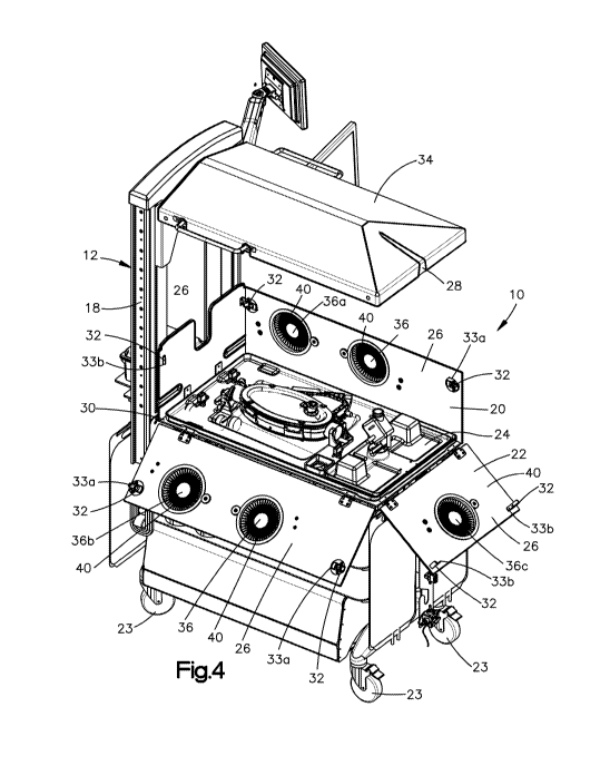
that defines a first length Li that is perpendicular to both the height H and
the width W. The slot
may include a second portion 128 that defines a second length L2 that is
perpendicular to both
the height H and the width W. Both the first length Li and the second length
L2 may be
measured from one side wall of the seal 120 to an opposing side wall of the
seal 120 that faces
the one side wall. According to one aspect of the disclosure the first length
Li is less than the
second length L2.
[0087] As shown in the illustrated embodiment, the first portion 126 of the
slot 124
may extend from a first outer surface 130 of the seal 120 toward a second
outer surface 132 of
- 16 -
CA 03047281 2019-06-14
WO 2018/111956 PCT/US2017/065950
the seal 120 that is opposite the first outer surface 130 of the seal 120. The
first outer surface
130 and the second outer surface 132 may each be surfaces that the height H is
normal to. The
seal 120 may terminate prior to reaching the second outer surface 132 of the
seal 120. As shown
the first portion 126 is positioned between the first outer surface 130 and
the second portion 128
with respect to the direction the height H is measured along.
[0088] The slot 124 may be configured to receive the cannula 140 when the
chamber
100 is in the open configuration. The cannula 140 may be moved through the
first portion 126 of
the slot 124 and then positioned within the second portion 128 of the slot
124. When the cannula
140 is positioned within the second portion 128, transitioning the chamber 100
into the closed
configuration causes both the first portion 126 to form a liquid tight barrier
and the second
portion 128 to form a liquid tight barrier around the cannula 140. As shown in
the illustrated
embodiment, the seal 120 may define three of the slots 124 arranged such that
the slots 124
extend through the seal 120 substantially perpendicular to one another. The
seal 120 may
include other numbers of the slots 124, for example less than three or more
than three, and other
arrangements of the slots 124, for example non-parallel to one another. As
shown in the
illustrated embodiment, the slot 124 may face the second portion 112 of the
chamber interior
space 102.
[0089] Referring to Fig. 14, the chamber 100 may include a port 160 configured
to
provide a passageway from the environment surrounding the chamber 100 to the
chamber
interior space 102 when the chamber 100 is in the closed configuration. As
shown in the
illustrated embodiment the chamber 100 may include a plurality of ports 160
including a first
port 160a and a second port 160b. The first port 160a and the second port 160b
may be
positioned opposite one another. For example the first port 160a may be
supported by the first
shell 114 and the second port 160b may be supported by the second shell 116.
The first port
160a may be positioned closer to the first end 180 of the chamber 100 than the
second port 160b
is to the first end 180, and the second port 160b may be positioned closer to
the second end 182
of the chamber 100 than the first port 160a is to the second end 182. As shown
in the illustrated
embodiment, the first port 160a and the second port 160b may be positioned
such that when the
fetus 2 is in the chamber 100 and the chamber 100 is in the closed
configuration, the first port
160a is positioned proximate the head 7 of the fetus 2 and the second port
160b is positioned
proximate the feet 9 of the fetus 2. The chamber 100 including the first port
160a proximate the
fetus' head and the second port 160b proximate the fetus' feet provides
selectable access to the
chamber interior space 102 to remove debris from the chamber interior space
102 that is
positioned either by the head 7 or feet 9 of the fetus 2.
- 17 -
CA 03047281 2019-06-14
WO 2018/111956 PCT/US2017/065950
[0090] Referring to Figs. 15 to 18, the port 160 is configured to provide
access for an
instrument 200, for example a suction wand 202, into the chamber interior
space 102 while
maintaining sterility of the chamber interior space 102. The port 160 may
include a first seal 162
that is biased closed. As shown in Figs. 15 to 17, when the instrument 200 is
removed from the
port 160, a slit 164 of the first seal 162 is biased closed. As shown in Fig.
18, the port 160 may
include a second seal 165 that is configured to form a seal around the
instrument 200 when the
instrument is inserted into the port 160. According to one embodiment, the
second seal 165 is
spaced from the first seal 162, and the second seal 165 defines an opening
166. The opening 166
may correspond to a shape, for example match a shape, of an exterior surface
of the instrument
200, such that when the instrument 200 is inserted into the port 160, the
opening 166 provides a
passageway for the instrument 200 and forms a seal with the instrument 200.
[0091] According to one aspect of the disclosure, the port 160 may include a
third seal
168 that is moveable from a first position to a second position. As shown in
Figs. 15 and 16, in
the first position, also referred to herein as a closed position, the third
seal 168 blocks the
passageway through the port 160, such that the instrument 200 cannot pass
through the port 160
into the chamber interior space 102. As shown in Figs. 17 and 18, the third
seal 168 may be
moved, for example translated, such that an opening 170 of the third seal 168
is aligned with the
passageway of the port 160, and the instrument 200 can pass through the port
160 into the
chamber interior space 102.
[0092] Referring to Figs. 19 to 22, according to another embodiment, the third
seal 168
of the port 160 may be similar to the second seal 164 as described above in
reference to Figs. 15
to 18, such that the third seal 168 is not movable from a first position to a
second position, but
rather the opening 170 is fixed in position to the passageway of the port 160
and corresponds to a
shape of the instrument 200, such that when the instrument 200 is inserted
into the port 160, the
opening 166 provides a passageway for the instrument 200 and forms a seal with
the instrument
200. As shown in the illustrated embodiment, the opening 170 may be larger
than the opening
166 when instrument 200 is removed from the port 160.
[0093] Referring to Figs. 23 to 26, the system 10 may include a port 260
instead of or
in addition to the port 160. The port 260 may include a housing 262 configured
to be attached to
one of the first shell 114 and the second shell 116. For example, an upper
surface 264 of the
housing 262 may be welded to one of the flexible wall 212a and 212b, for
example the side of
the flexible wall 212a and 212b that faces the interior space 102.
Alternatively, the housing 262
may be configured to be welded to the side of the flexible wall 212a and 212b
that faces away
- 18 -
CA 03047281 2019-06-14
WO 2018/111956 PCT/US2017/065950
from the interior space 102. The housing 260 defines a first opening 266, a
second opening 268
and a recess 270 that extends from the first opening 266 to the second opening
268.
[0094] The port 260 further includes an insert 272 positioned within the
recess 270.
The insert 272 is configured to create a seal, for example a liquid-tight
seal, an air-tight seal, or
both, between the first opening 266 and the second opening 268. The insert 272
includes an
elastically deformable material with a slit 274. The insert 272 is configured
to allow the
instrument 200 to be inserted into the slit 274 and form a seal around the
instrument 200 as the
instrument is inserted through the slit 274. The insert 272 may include a
first material 276, for
example silicone, configured to compress as the instrument 200 is inserted
into the slit 274 and
apply a biasing force against the instrument 200 thereby maintaining a seal
between the first
opening 266 and the second opening 268.
[0095] The insert 272 may further include a second material 278, for example a
polycarbonate, that is stiffer than the first material 276. The second
material 278 may be
positioned around the first material 276 and may include an attachment
mechanism to secure the
insert 272 within the recess 270.
[0096] The port 260 may also include a cap assembly 280. The cap assembly 280
includes a body 282 that defines an opening 284 configured to guide the
instrument to the slit
274. The cap assembly 280 may be attached to the housing 260, for example
threadedly attached
with corresponding threads.
[0097] Referring to Fig. 27, the system 10 includes a first fluid circuit 300,
which is
configured to deliver a fluid 302 from a source 304 to the chamber 100, and
then deliver the fluid
302 from the chamber 100 to a reservoir 306. The fluid 302 may be a sterile
solution, for
example an electrolyte solution. The source 304 may include multiple source
containers, for
example a first source container 308a and a second source container 308b. The
multiple source
containers may be arranged in parallel such that the fluid 302 can be
delivered from one or
another of the multiple source containers. According to one aspect of the
disclosure, the first
fluid circuit 300 includes a valve 310 that is configured to provide passage
of the fluid 302 from
the source 304 to the chamber 100 when the valve 310 is in an open
configuration, and the valve
310 is further configured to block passage of the fluid 302 from the source
304 to the chamber
100 when the valve 310 is in a closed configuration.
[0098] As shown in the illustrated embodiment, the valve 310 may be a three-
way
valve that includes a first open configuration in which the valve 310 provides
passage of the fluid
302 from the first source container 308a to the chamber 100 while blocking
passage of the fluid
302 from the second source container 308b to the chamber 100. The three-way
valve may
- 19 -
CA 03047281 2019-06-14
WO 2018/111956 PCT/US2017/065950
further include a second open configuration in which the valve 310 provides
passage of the fluid
302 from the second source container 308b to the chamber 100 while blocking
passage of the
fluid 302 from the first source container 308a to the chamber 100. The valve
310 being a three-
way valve as described above would allow for the fluid 302 from the first
source container 308a
to be delivered to the chamber 100 until the first source container 308a is
empty, then the valve
310 could be transitioned from the first open configuration to the second open
configuration
allowing the fluid 302 from the second source container 308b to be delivered
to the chamber
100, while allowing the, now empty, first source container 308a to be replaced
with a new
container.
[0099] The first fluid circuit 300 includes a pump 312, for example a
peristaltic pump,
configured to move the fluid 302 from the source 304 to the chamber 100. The
first fluid circuit
300 may include a first pressure sensor 314a positioned between the pump 312
and the chamber
100, a second pressure sensor 314b positioned within the chamber 100, a third
pressure sensor
314c positioned between the chamber 100 and the reservoir 306, a fourth
pressure sensor 314d,
or any combination thereof Each of the pressure sensors 314a, 314b, 314c, and
314d may be
configured to output a numerical value representing the current pressure
within the first fluid
circuit 300 between the pump 312 and the chamber 100 to a display viewable by
a user of the
system 10.
[0100] The first fluid circuit 300 may include a filters 316 configured to
block
particulates in the fluid 302 from reaching the chamber 100. The filter 316
may be configured to
block particulates of a selected size, for example particles greater than
about 0.22 micrometers.
The filter 316 may be one of a plurality of filters 316 that can be arranged
in parallel or in series.
The plurality of filters 316 may be configured to block particulates of the
same size, or of
different sizes. For example a first of the plurality of filters 316 may be
configured to block
particulates of a first size, and a second of the plurality of filters 316 may
be configured to block
particulates of a second size. The first size may be larger than the second
size, and the second of
the plurality of filters 316 may be positioned between the first of the
plurality of filters 316 and
the chamber 100.
[0101] The first fluid circuit 300 may include a heat source 318 configured to
change a
temperature of the fluid 302 prior to reaching the chamber 100. The heat
source 318 may
include one or more heaters 320 configured to increase the temperature of the
fluid 302. The
first fluid circuit 300 may include a turbidity meter 322, configured to
measure the clarity of the
fluid 302. The turbidity meter 322 may be positioned within the chamber 100
and configured to
send a signal, for example activate an alarm of the system 10, when a level of
cloudiness is
- 20 -
CA 03047281 2019-06-14
WO 2018/111956 PCT/US2017/065950
present within the fluid 302. Cloudiness in the fluid 302 may be caused by a
contaminate in the
fluid 302 in the chamber 100, for example meconium. The turbidity meter 322
may be
configured to detect blood in the chamber 100. The presence of blood in the
chamber 100 may
signal a decannulation event, which may require rapid detection and
notification to minimize
potential harm to the infant 2.
[0102] The system 10 is configured to facilitate removal of the contaminate in
the fluid
302 in the chamber 100 while maintaining the chamber 100 in the closed
configuration. For
example the suction wand 202 may be inserted into the chamber 100, for example
through one of
the ports as described above, and used to remove the contaminate. The suction
wand 202 may be
connected to a vacuum source 204, for example a mobile vacuum source or a
fixed vacuum
source.
[0103] The first fluid circuit 300 may include a release valve 324 configured
to provide
release the fluid 302 within the chamber 100 more quickly than the fluid 302
would normally
exit the chamber 100 toward the reservoir 306. If the pressure of the fluid
302 within the
chamber 100 reaches a value above a desired level, or if quick access to the
fetus 2 is desired,
actuation of the release valve 324 will empty the chamber 100 of the fluid 302
currently within
the chamber 100.
[0104] The first fluid circuit 300 may include a flow meter 326 configured to
measure a
rate at which the fluid 302 is moving through the first fluid circuit 300. The
first fluid circuit 300
may include a first flow meter 326 positioned between the pump 312 and the
chamber 100 such
that the first flow meter 326 is configured to measure the flow rate of the
fluid 302 into the
chamber 100, a second flow meter 326 positioned between the chamber 100 and
the reservoir
306 such that the second flow meter 326 is configured to measure the flow rate
of the fluid 302
out of the chamber 100, or both.
[0105] The first fluid circuit 300 may include a filtration system 328
positioned
between the chamber 100 and the reservoir 306. The filtration system 328 is
configured to
prevent contaminates, such as bacteria, from migrating toward the chamber 100
along a direction
that is opposite the direction of flow of the fluid 302. According to one
aspect of the disclosure,
the filtration system 328 is configured to kill bacterial growth that migrates
from the reservoir
306 toward the chamber 100.
[0106] The first fluid circuit 300 may include a pressure regulator 330
configured to
adjust the pressure of the fluid 302 within the chamber 100. The pressure
regulator 330 may
include an actuator that is configured to receive an input, for example a
manual input that
- 21 -
CA 03047281 2019-06-14
WO 2018/111956 PCT/US2017/065950
includes raising or lowering the actuator with respect to the surface the
system 10 is positioned
upon, to raise or lower, respectively, the pressure of the fluid 302 within
the chamber 100.
[0107] Referring to Figs. 27 and 28, the pressure regulator 330 may include a
pressure
chamber 331, a first port 333 coupled to the pressure chamber 331 and a second
port 335 coupled
to the pressure chamber 331. The pressure regulator 330 may be configured such
that the fluid
302 discharged from the chamber 100 enters the pressure chamber 331 through
the first port 333
and exits through the second port 335 on the way towards the reservoir 306. As
shown in the
illustrated embodiment, the pressure chamber 331 is slidably mounted to the
cart 12, for example
on a pair of rails 337. According to one aspect of the disclosure, the
pressure inside the interior
space 102 may be adjusted by adjusting the height of the pressure chamber 331
relative to the
interior space 102. For example, the system 10 may be configured such that by
sliding the
pressure chamber 331 "up" along the rails 337 thereby increasing the height of
the pressure
chamber 331 relative to the interior space 102, the fluid 302 exiting the
interior space 102 must
travel "up" against gravity, thereby increasing the pressure within the
interior space 102. The
system 10 may further be configured such that by sliding the pressure chamber
331 "down"
along the rails 337 thereby decreasing the height of the pressure chamber 331
relative to the
interior space 102, the fluid 302 exiting the interior space 102 has less of a
vertical distance to
travel "up" against gravity, thereby decreasing the pressure within the
interior space 102.
[0108] The reservoir 306 may include multiple reservoir containers, for
example a first
reservoir container 332a and a second reservoir container 332b. The multiple
reservoir
containers may be arranged in parallel such that the fluid 302 can be
delivered from one or
another of the multiple reservoir containers 332a and 332b. According to one
aspect of the
disclosure, the first fluid circuit 300 includes a valve 334 that is
configured to provide passage of
the fluid 302 from the chamber 100 to the reservoir 306 when the valve 334 is
in an open
configuration, and the valve 334 is further configured to block passage of the
fluid 302 from the
chamber 100 to the reservoir 306 when the valve 334 is in a closed
configuration.
[0109] As shown in the illustrated embodiment, the valve 334 may be a three-
way
valve that includes a first open configuration in which the valve 334 provides
passage of the fluid
302 from chamber 100 to the first reservoir container 332a while blocking
passage of the fluid
302 from the chamber 100 to the second reservoir container 332b. The three-way
valve may
further include a second open configuration in which the valve 334 provides
passage of the fluid
302 from the chamber 100 to the second reservoir container 332b while blocking
passage of the
fluid 302 from the chamber 100 to the first reservoir container 332a. The
valve 334 being a
three-way valve as described above would allow for the fluid 302 from the
chamber 100 to be
- 22 -
CA 03047281 2019-06-14
WO 2018/111956 PCT/US2017/065950
delivered to the first reservoir container 332a until the first reservoir
container 332a is full, then
the valve 334 could be transitioned from the first open configuration to the
second open
configuration allowing the fluid 302 from the chamber 100 to be delivered to
the second
reservoir container 332b, while allowing the, now full, first reservoir
container 332a to be
removed and replaced with a new, empty container.
[0110] Referring to Figs. 27 and 29 to 30, the filtration system 328 may
include an
ultraviolet light source 360 configured to deliver an amount of ultraviolet
light to the fluid 302
between the chamber 100 and the reservoir 306. Bacteria or other contaminants
may grow
within the reservoir 306 and grow or migrate toward the chamber 100
retrograde, or opposite the
flow of the fluid 302. The filtration system 328 is configured to eradicate
the contaminate before
the contaminate reaches the chamber 100.
[0111] The filtration system 328 may include a housing 362 configured to limit
an
amount of ultraviolet light that exits the filtration system 328. According to
one embodiment,
the housing 362 defines an open configuration (as shown in Fig. 30) and a
closed configuration
(as shown in Fig. 29). In the closed configuration the housing 362 is
configured to block a
portion, for example all, of the ultraviolet light from reaching the chamber
100. The filtration
system 328 may include a length of tubing 364 that is exposed to the
ultraviolet light source 360
and that carries the fluid 302 between the chamber 100 and the reservoir 306.
[0112] The housing 362 may include a first seal 366 and a second seal 368 that
are each
configured to receive the tubing 364 such that when the tubing 364 is
positioned within the first
seal 366 and the second seal 368, the first seal 366 and the second seal 368
form a light barrier
around the tubing 364 preventing the ultraviolet light from exiting the
housing 362. The first
seal 366, the second seal 368, or both may include a slot 370 extending from
an outer surface
372 in a direction substantially perpendicular to the direction of flow of the
fluid 302 within the
tubing 364. The slot 370 may be configured to facilitate sliding engagement of
the tubing 364
with the respective seal. The housing 362 may include a reflective surface 374
positioned within
the housing 362 such that the reflective surface 374 is configured to reflect
the ultraviolet light to
additional areas of the tubing 364 that are not directly exposed to the
ultraviolet light source 360.
[0113] The filtration system 328 defines a length L3 measured along the
section of
tubing that is exposed to the ultraviolet light and measured in the direction
of the flow of the
fluid 302. According to one aspect of the disclosure, the length L3 is greater
than about 0.8
inches, the irradiance provided by the ultraviolet light source 360 is about
100 microwatts per
centimeter squared, the cross-sectional area of the tubing 364 is about 0.22
centimeters squared,
- 23 -
CA 03047281 2019-06-14
WO 2018/111956 PCT/US2017/065950
and the flowrate of the fluid 302 through the tubing 364 may be up to about 32
milliliters per
minute.
[0114] Thus a method of providing care for the fetus 2, for example the method
of
moving the fetus 2 from the uterus of a patient 6 to an ex utero environment,
may include the
step of exposing a portion of a first fluid circuit 300 that flows through the
chamber 100 to
ultraviolet light.
[0115] Referring to Fig. 31, the system 10 includes a second fluid circuit 400
configured to provide gas transfer between the fetus 2 and the oxygenator 60.
Specifically, the
second fluid circuit 400 is configured to provide oxygen to and remove carbon
dioxide from the
blood of the fetus 2. The second fluid circuit 400 may include a first portion
500 configured to
deliver a sweep gas 408 to the oxygenator 60, and a second portion 502
configured to accept the
sweep gas 408 and perform gas exchange with the blood supply of the fetus 2.
The second
portion 502 may include the oxygenator 60 connected with the fetus 2 by two
fluid lines of the
second fluid circuit 400. The two fluid lines include an outflow line 402 and
an inflow line 404.
The blood of the fetus 2 flows from the fetus 2 though the outflow line 402 to
the oxygenator 60,
the blood then flows through the oxygenator 60 and returns to the fetus 2
through the inflow line
404. The outflow line 402 and the inflow line 404 pass through the seal 120,
for example by
way of the cannulae 140.
[0116] The system 10 may be configured such that the oxygenator 60 is
positioned
close to the chamber 100 such that the lengths of the outflow line 402 and the
inflow line 404, to
and from the oxygenator 60 respectively, are minimized. For instance, in
accordance with one
aspect of the disclosure, the outflow line 402 and the inflow line 404 are
less than about 36
inches long combined. By minimizing the lengths of the outflow line 402 and
the inflow line
404, the volume of blood required to prime the second fluid circuit 400 is
minimized. It may be
desirable to line the outflow line 402 the inflow line 404, or both with anti-
clotting
measures/compounds (for example, but not limited to, immobilized polypeptide,
heparin, or
both).
[0117] The oxygenator 60 may be primed prior to connection with the fetus 2.
According to one embodiment, the oxygenator 60 may be primed with a
crystalloid solution
containing human albumin. The second fluid circuit 400 may then be further
primed with, for
example, maternal blood, blood of the fetus 2, or both. Priming of the second
fluid circuit 400
with hemoglobin from the fetus 2 may result in optimal oxygen exchange in the
second fluid
circuit 400. Because the fetal oxygen dissociation curve is shifted to the
left compared to the
adult oxygen dissociation curve, fetal arterial oxygen pressures are lower
than adult arterial
- 24 -
CA 03047281 2019-06-14
WO 2018/111956 PCT/US2017/065950
oxygen pressures. In a one embodiment, the blood in the second fluid circuit
400 includes
heparin. According to another embodiment, the blood in the second fluid
circuit 400 is devoid of
heparin.
[0118] According to one aspect of the disclosure, the first portion 500 of the
second
fluid circuit 400 produces a sweep gas 408 and delivers the sweep gas 408 to
the oxygenator 60,
the sweep gas 408 is configured to facilitate gas transfer between the
oxygenator 60 and the
blood of the fetus 2. The gas transfer is affected by the composition of the
sweep gas 408 and
the flow rate of the sweep gas 408 through the oxygenator 60. A plurality of
gases may be
blended together in a gas blender 410 that blends the plurality of gases to
form the sweep gas.
According to one aspect of the disclosure, the plurality of gases may include,
but is not limited
to, oxygen, nitrogen, carbon dioxide, nitric oxide, air, or any combination
thereof As shown in
the illustrated embodiment, the plurality of gases may include at least a
first gas 412 and a
second gas 414. The plurality of gases may further include a third gas 416, a
fourth gas 417, a
fifth gas 419, or any combination thereof According to one aspect of the
disclosure, any or all
of the plurality of gases may be supplied by multiple sources such as a
mobile, smaller source,
and a larger, fixed source.
[0119] As an example, the second fluid circuit 400 may include a mobile first
gas
source 418a, for example that is attached to and carried by the cart 12, and a
fixed first gas
source 418b that is fixed in place, for example as part of the infrastructure
of a hospital room.
The second fluid circuit 400 may further include a mobile second gas source
420a, a fixed
second gas source 420b, a mobile third gas source 422a, a fixed third gas
source 422b, a mobile
fourth gas source 424a, a fixed fourth gas source 424b, a mobile fifth gas
source 427a, a fixed
fifth gas source 427b, or any combination thereof
[0120] The first portion 500 of the second fluid circuit 400 may include a
plurality of
valves 426 each configured to control whether the mobile or fixed source of
each respective gas
source is connected with the second fluid circuit 400. The second fluid
circuit 400 may include
one or more pressure sensors 428 positioned inline with each of the plurality
of gas supplies, the
plurality of pressure sensors 428 configured to measure the gas pressure of
the plurality of gases
being fed to the second fluid circuit 400. The second fluid circuit 400 may
further include one or
more pressure regulators 429 configured to provide receive a variable pressure
from the
respective gas source and deliver a steady, constant pressure of the
respective gas. As shown in
the illustrated embodiment, the pressure regulator 429 may be positioned
between two of the
pressure sensors 428, which may be configured to measure the pressure going
into and coming
out of the pressure regulator 429.
- 25 -
CA 03047281 2019-06-14
WO 2018/111956 PCT/US2017/065950
[0121] The second fluid circuit 400 may be configured such that one or more of
the
plurality of gases enter the gas blender 410. As shown in the illustrated
embodiment, the first
gas 412 and one of the second gas 414 and the third gas 416 may enter the gas
blender 410.
According to one aspect of the disclosure, the first gas 412 is oxygen, the
second gas 414 is
nitrogen, and the third gas 416 is air. The gas blender 410 outputs a mixed
gas 425. The second
fluid circuit 400 may be configured such that one or more of the plurality of
gases combines with
the mixed gas 425 after the mixed gas 425 exits the gas blender 410. According
to one
embodiment, the plurality of gases includes oxygen, nitrogen, and air coupled
to the second fluid
circuit 400 such that the oxygen and one of nitrogen and the air enter the gas
blender 410 to form
the mixed gas 425. The second fluid circuit 400 may include the fourth gas
417, the fifth gas
419, or both connected to the mixed gas 425 to form the sweep gas 408. The
fourth gas may
include carbon dioxide and the fifth gas may include nitric oxide, according
to one aspect of the
disclosure that are each configured to be added to the mixed gas 425 after the
mixed gas 425
exits the gas blender 410, to form the sweep gas 408.
[0122] The second fluid circuit 400 may include a heater, for example the
heater 42, or
a different heater that is positioned inline between the gas blender 410 and
the oxygenator 60, the
heater configured to heat the sweep gas 408 so that the temperature of the
sweep gas 408 is
maintained within a predetermined range. The second fluid circuit 400 may
include a fluid flow
regulator 430 configured to monitor, adjust, or both the flow rate of the
sweep gas 408. The
second fluid circuit 400 may further include a sweep gas analyzer 432
configured to analyze one
or more characteristics of the sweep gas 408 entering the oxygenator 60.
[0123] The second fluid circuit 400 may include an exhaust gas analyzer 434
configured to analyze one or more characteristics of the gas discharged by the
oxygenator 60.
For instance, the gas analyzers 432 and 434 may be configured to measure the
oxygen content of
the sweep gas and the exhaust gas, respectively. As shown in the illustrated
embodiment, the
fluid flow regulator 430 may be positioned between the sweep gas analyzer 432
and the
oxygenator 60.
[0124] The second fluid circuit 400 further includes a pair of fluid pressure
sensors 436
and 438 configured to detect the fluid pressure of the blood entering the
oxygenator 60 and the
fluid pressure of the blood exiting the oxygenator 60, respectively.
Specifically, the first
pressure sensor 436 may be positioned in-line with the outflow line 402 and
the second pressure
sensor 438 may be positioned in-line with the inflow line 404. In this way,
the fluid pressure
drop over the oxygenator 60 can be continuously monitored. Additionally, a
fluid flow meter
- 26 -
CA 03047281 2019-06-14
WO 2018/111956 PCT/US2017/065950
440 may be positioned in-line with the inflow line 404 to monitor the flow
rate of the blood
returning to the fetus 2 from the oxygenator 60.
[0125] The second fluid circuit 400 may include one or more ports 442, which
may be
utilized to withdraw blood samples for analysis or the ports 442 may be used
to inject or infuse
medicine or nutrition directly into the blood. For instance, one of the ports
442 may be
configured to facilitate injection of medication such as antibiotics or
sedatives into the blood.
Similarly, another of the ports 442 may be configured to facilitate injection
of nutrition such as
total parental nutrition (TPN) into the blood.
[0126] The second portion 502 of the second fluid circuit 400 may include a
first sensor
437 and a second sensor 439 positioned such that the oxygenator 60 is between,
for example
directly between, the first sensor 437 and the second sensor 439. The first
sensor 437 and the
second sensor 439 may configured to measure one or more variables of the blood
of the fetus 2
just before entering the oxygenator 60 and just after exiting the oxygenator
60, respectively, so
that the change provided by the oxygenator can be measured and monitored. The
first sensor
437 and the second sensor 439 may each be configured to measure blood flow,
blood oxygen
levels, blood hemoglobin levels, or any combination thereof According to one
embodiment, the
first sensor 437 and the second sensor 439 each use absorbance spectroscopy to
measure the
amount of oxygen bound to hemoglobin, and levels of hemoglobin. Blood flow may
be
measured by ultrasound.
[0127] In accordance with one aspect of the disclosure, the heart of the fetus
2 drives
blood flow through the second portion 502 of the second fluid circuit 400,
such that the second
portion 502 of the second fluid circuit 400 is devoid of a pump. In other
words, according to one
aspect of the disclosure, the second portion 502 of the second fluid circuit
400 is a pumpless
circuit. The use of a pumpless system avoids exposure of the heart of the
fetus 2 to excess
preload encountered in non-pulsatile pump-assisted circuits. The pumpless
system also permits
intrinsic fetal circulatory regulation of flow dynamics. The oxygenator 60
preferably has very
low resistance, low priming volume, low transmembrane pressure drops, and
provides efficient
gas exchange. The first portion 500 of the second fluid circuit 400 may be
driven by an external
pressure source.
[0128] In accordance with one embodiment, the oxygenator 60 has a pressure
drop of
less than about 50 mmHg or about 40 mmHg at 1.5 liters per minute of blood
flow. In a
particular embodiment, the priming volume of the oxygenator 60 is less than
about 100
milliliters and in particular is less than about 85 milliliters. In a
particular embodiment, the
oxygenator 60 has a blood flow range up to about 2.0 liters per minute, about
2.5 liters per
- 27 -
CA 03047281 2019-06-14
WO 2018/111956 PCT/US2017/065950
minute, about 2.8 liters per minute, or greater. In a particular embodiment,
the oxygenator 60
has a gas transfer rate of about 150 milliliters per minute, about 160
milliliters per minute, about
180 milliliters per minute, or greater for oxygen. In a particular embodiment,
the oxygenator 60
is a hollow fiber membrane oxygenator (for example, but not limited to, a
polymethyl pentene
hollow fiber membrane oxygenator). The oxygenator 60 may be lined with anti-
clotting
measures/compounds such as immobilized polypeptide and/or heparin).
[0129] The system 10 may be configured for use with fetuses, including term
and
preterm fetuses. The preterm fetus may be a premature fetus (for example, less
than 37 weeks
estimated gestational age, particularly 28 to 32 weeks estimated gestational
age), extreme
premature fetuses (24 to 28 weeks estimated gestational age), or pre-viable
fetuses (20 to 24
weeks estimated gestational age). The gestation periods are provided for
humans, though
corresponding preterm fetuses of other animals may be used. In a particular
embodiment, the
preterm fetus has no underlying congenital disease. In a particular
embodiment, the term or
preterm fetus has limited capacity for pulmonary gas exchange, for example,
due to pulmonary
hypoplasia or a congenital anomaly affecting lung development, such as
congenital
diaphragmatic hernia. In a particular embodiment, the subject is a preterm or
term neonate
awaiting lung transplantation, for example, due to congenital pulmonary
disease (e.g.,
bronchoalveolar dysplasia, surfactant protein B deficiency, and the like).
Such transplantation
surgeries are currently rarely performed in the United States. However, the
number of
transplantation surgeries may be increased with the more stable method for
pulmonary support
provided by the instant invention. The fetus 2 may also be a candidate for ex
utero intrapartum
treatment (EXIT) delivery, including patients with severe airway lesions and a
long expected
course before definitive resection. The fetus 2 may also be a fetal surgical
or fetoscopic
procedure patient, particularly with preterm labor precipitating early
delivery. According to one
aspect of the disclosure the system 10 is configured such that the fetus 2 may
be maintained in
the system 10 for as long as needed (for example, for days, weeks or months,
until the fetus 2 is
capable of life without the system 10).
[0130] It will be appreciated that the foregoing description provides examples
of the
disclosed system and methods. However, it is contemplated that other
implementations of the
disclosure may differ in detail from the foregoing examples. All references to
the disclosure or
examples thereof are intended to reference the particular example being
discussed at that point
and are not intended to imply any limitation as to the scope of the disclosure
more generally. All
language of distinction and disparagement with respect to certain features is
intended to indicate
- 28 -
CA 03047281 2019-06-14
WO 2018/111956 PCT/US2017/065950
a lack of preference for those features, but not to exclude such from the
scope of the disclosure
entirely unless otherwise indicated.
[0131] Recitation of ranges of values herein are merely intended to serve as a
shorthand
method of referring individually to each separate value falling within the
range including the
stated ends of the range, unless otherwise indicated herein, and each separate
value is
incorporated into the specification as if it were individually recited herein.
All methods
described herein can be performed in any suitable order unless otherwise
indicated herein or
otherwise clearly contradicted by context.
[0132] Although the disclosure has been described in detail, it should be
understood
that various changes, substitutions, and alterations can be made herein
without departing from
the spirit and scope of the invention as defined by the appended claims.
Moreover, the scope of
the present disclosure is not intended to be limited to the particular
embodiments described in the
specification. As one of ordinary skill in the art will readily appreciate
from the disclosure of the
present invention, processes, machines, manufacture, composition of matter,
means, methods, or
steps, presently existing or later to be developed that perform substantially
the same function or
achieve substantially the same result as the corresponding embodiments
described herein may be
utilized according to the present disclosure.
- 29 -