Note: Descriptions are shown in the official language in which they were submitted.
CA Application
Blakes Ref: 10778/000001
¨ 1 -
APPARATUS FOR DISPENSING A HEATED LIQUID FOODSTUFF
TECHNICAL FIELD
[0001] The invention relates to an apparatus for dispensing a
heated liquid foodstuffs, in particular a hot drink, such as
preferably coffee, with a Heating device for the liquid foodstuff
and a dispensing nozzle.
STATE OF THE ART
[0002] Such an apparatus is known for example from DE 10046558 Al.
a liquid foodstuff is delivered as needed from a storage reservoir
by means of a pump provided in the apparatus, which liquid
foodstuff is heated by a heating device in the form of a heat
exchanger before its removal via a dispensing nozzle.
SUMMARY OF THE INVENTION
[0003] In view of the state of the art described above, a task of
the invention is considered to be to further improve an apparatus
of the kind under discussion in advantageous manner.
[0004] One possible solution to the task is provided according to
an inventive thought, the objective of which is that the liquid
foodstuff be dischargeable from a receptacle under pressure and
that a pressure reducing device be arranged before the heating
device.
[0005] The liquid foodstuff is preferably discharged from a
beverage container which is subjected to a positive pressure of
for example 2 bar up to for example 3 bar. Alternatively, a pump
with a maximum discharge or cutoff pressure of up to about 3 bar
may also be provided, preferably outside of the apparatus. In order
to reduce the fluid pressure acting in delivery direction before
the heating device and therewith also before the dispensing nozzle,
a pressure reducing device is provided before the heating device
when considered in the delivery direction. Via this, a reduction
23676878.1
CA 3047300 2019-06-19
CA Application
Blakes Ref: 1 0 7 7 8/0 0 0 0 0 1
- 2 -
of the fluid pressure may be induced, for example to a delivery
and/or cutoff pressure usual for dispensing apparatuses of about
1 to 2 bar, more preferably about 1.5 bar.
[0006] Accordingly, the heating device is provided between the
pressure reducing device and the dispensing nozzle when considered
in delivery direction of the liquid foodstuff.
[0007] Further features of the invention are explained in the
following text, also in the description of figures, often in their
preferred assignment to the object of claim 1 or to features of
further claims. But they may also be of significance in an
assignment to only individual features of claim 1 or of the
respective further claim or independently in each case.
[0008] Accordingly, the pressure reducing device may consist of a
pressure reducing valve integrated in a feed line for the liquid
foodstuff. In this context, the feed line may be part of the
pressure reducing device at least in a portion thereof.
[0009] The pressure reducing valve may also be embodied as a
plunger with a conical end facing against the delivery direction,
which is inserted in a correspondingly conically formed section of
the feed line. In this way, a compensator for the pressure
reduction is created. This may be designed, as also preferably, in
the form of an inline compensator. Within the compensator, a
reduction of the flow rate per unit of time is achieved, wherein
the liquid foodstuff flows around the plunger and permeates an
annular space created between the plunger outer surface and facing,
enclosing inner surface of the feed line.
[0010] In order to adjust the pressure reduction, correspondingly
to adjust the reduced, outlet-side fluid pressure, the plunger may
be displaceable relative to the feed line in the longitudinal
direction of the feed line, more preferably in and counter to the
delivery direction of the liquid foodstuff. Such an adjustment may
23676878.1
CA 3047300 2019-06-19
CA Application
Blakes Ref: 10778/000001
- 3 -
be carried out, as preferably, from the outside. Thus additionally,
such an adjustment may also be made while liquid foodstuff is
propelled through the compensator.
[0011] In one possible variant, the heating device consists of a
section of the feed line which is acted upon by means of a thermal
conductor. The transfer of heat to the liquid foodstuff may take
place as a consequence of a heated solid material in which the
thermal conductor may be embedded. In preferred variant, the
heatable solid material completely surrounds the feed line in the
heating device section in question to achieve preferably even heat
transfer. In this context, the solid material serves as heat
exchanger, for which purpose the solid material is equipped with
a thermal conductor.
[0012] The thermal conductor embedded in the solid material may be
a liquid line.
[0013] In addition, according to a preferred variant the delivery
line may be a steel pipe, in particular a stainless steel pipe,
which passes through the solid material in the region of the
heating device. In such context, the solid material may consist of
aluminium. Here it may be advisable to heat the solid material up
by means of a resistance heater. Correspondingly, according to a
preferred variant an electrically powered heating device may be
provided.
[0014] The stainless steel pipe forming the feed line may be cast
in an aluminium block together with for example up to three heating
elements of a resistance heater, whereby a very favourable heat
transfer may be achieved. The thermal energy which is supplied to
the aluminium solid material by the heating elements of the
resistance heater is transferred to the liquid foodstuff flowing
through the stainless steel pipes indirectly due to the good
thermal conductivity of the aluminium.
23676878.1
CA 3047300 2019-06-19
CA Application
Blakes Ref: 10778/000001
- 4 -
[0015] According to a preferred variant, the apparatus may
essentially have a front face with the dispensing nozzle and two
oppositely positioned side walls optionally extending
substantially vertically in the operating state, and a rear wall.
The apparatus may further have a bottom and a top cover.
Accordingly, in this way an overall cuboid shape of the apparatus
may be created. An overall circular cylindrical or barrel-like
shape of the apparatus may also be created, wherein the front face
and optionally the rear wall may be constructed in the form of
circular discs.
[0016] In preferred variant, the pressure reduction device and the
heating device in are arranged inside the apparatus, while the
receptacle under pressure is provided outside the apparatus.
Pressure reducing device and heating device are thus part of the
apparatus, whereas the pressurised receptacle or a receptacle with
a connected external pump for generating the pressure may
optionally be connected to the apparatus.
[0017] In a further possible variant, the pressure reducing device
may be accessible from a side wall of the apparatus. To this end,
the side wall as a whole or a partial area thereof may be pivotable
downwards or upwards, also optionally completely removable. The
pressure reducing device is accessible through the opening created
thereafter, for example for cleaning or replacement purposes, also
optionally for adjusting the pressure reduction.
BRIEF DESCRIPTION OF THE DRAWINGS
[0018] In the following text, the invention will be explained in
greater detail with reference to the accompanying drawing, which
represents only a single embodiment. It shows:
Fig. 1 a perspective, schematic representation of an apparatus
for dispensing a heated liquid foodstuff with an attached
receptacle for the liquid foodstuff;
23676878.1
CA 3047300 2019-06-19
CA Application
Blakes Ref: 10778/000001
- 5 -
Fig. 2 a schematic representation of a cross-section through the
apparatus with the apparatus housing replicated by a dot-
dashed line style;
Fig. 3 a pressure reducing device of the apparatus in perspective
representation;
Fig. 4 the pressure reducing device in detail view;
Fig. 5 the section through the pressure reducing device along
line V-V in Figure 4.
DESCRIPTION OF THE EMBODIMENTS
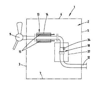
[0019] An apparatus 1 for dispensing a heated liquid foodstuff is
represented and described, firstly with reference to Figure 1.
Such a foodstuff here may as also preferably be a hot drink,
further for example such as coffee.
[0020] The apparatus has a housing 2 with a front face 3, in the
embodiment shown two oppositely positioned side walls 4 extending
substantially vertically in the operating state, and a rear wall
5. On the upper side, the housing 2 is covered by a top face 6.
Below, the housing 2 is delimited by a bottom 7.
[0021] The apparatus 1 supports itself on a work surface by means
of adjustable feet 8 arranged underneath the bottom 7.
[0022] At least one dispensing nozzle 9 is arranged in the area of
the front face 3. In the embodiment represented, two dispensing
nozzle 9 are provided for dispensing two possibly different
beverages, in particular hot drinks. However, it is also possible
for example that one hot drink and one cold drink may be dispensed
via the two dispensing nozzles 9.
[0023] A drip tray 10 is provided at the front and attached to the
bottom 7 with vertical separation from the dispensing nozzles 9.
23676878.1
CA 3047300 2019-06-19
CA Application
Blakes Ref: 10778/000001
- 6 -
[0024] The apparatus 1 serves for dispensing a liquid which is
stored in a receptacle 11 that is arranged outside the housing 2.
[0025] The receptacle 11 may be pressurised, as is preferred, so
that for example a discharge pressure of about 2.5 to 3 bar
results. This pressure may also be generated by an external pump
in the case of an unpressurised receptacle.
[0026] The liquid foodstuff is passed through a feed line 12
provided between receptacle 11 and apparatus 1, wherein the section
of the feed line 12 between receptacle 11 and apparatus 1 is
preferably a tube line.
[0027] A tube line may also be provided substantially inside the
apparatus 1 to fulfil the function of the feed line 12, wherein
the feed line 12 inside the apparatus 1 substantially constitutes
the line connection to the assigned dispensing nozzle 9.
[0028] An electrically powered heating device 13 is provided in
the apparatus 1. This heating device 13 firstly consists
substantially of a block of a solid material 14, consisting
particularly of aluminium which encloses the feed line 12. In one
possible variant, the section of the feed line 12 which passes
through this solid material 14 is in the form of a stainless steel
pipe. The outer wall of the feed line 12 in this section is
preferably in full surface contact with the facing hole wall of
the solid material 14.
[0029] Electric heating elements 15 are embedded in the solid
material 14. Here, the arrangement of a plurality of heating
elements 15, for example two, three or for heating elements, is
preferred.
23676878.1
CA 3047300 2019-06-19
CA Application
Blakes Ref: 10778/000001
- 7 -
[0030] The heating element 15 and the section of the feed line 12
which passes through the solid material may be cast in the solid
material 14, as is also preferred.
[0031] For the electrical supply to the heating elements 15, the
apparatus 1 is provided with an electrical connection 16,
represented schematically in Figure 1.
[0032] The heat output of the heating element 15 may optionally
be controllable. For this purpose, a temperature regulator 17 may
be provided in the area of the front face 3 and may also have a
switching function for starting and switching off the heating
element 15.
[0033] In order to reduce the fluid pressure, a pressure reducing
device 18 is provided before the heating device 13 when viewed in
the delivery direction. The pressure reducing device is arranged
inside the apparatus 1, in particular inside the housing 2 and
consists substantially of a pressure reducing valve 19 integrated
in the feed line 12.
[0034] In this context, the pressure reducing device 18 is designed
substantially as an elongated tube, in this context in the
direction of the longitudinal extension, which corresponds to the
feed direction, having a housing which is divided into two parts,
with a first housing part 20 and a second housing part 21.
[0035] The two housing parts 20 and 21 may be connected by screwing
to each other by means of a thread 22 which extends concentrically
with the longitudinal axis x of the device.
[0036] Each housing part 20, 21 forms a pipe-like connecting
section 23, 24 12 at the free end of each farthest from the thread
22 for the feed line. The tubular feed line 12 preferably aligned
in the delivery direction r is preferably pushed onto the ends so
that the corresponding connecting sections 23 and 24 seen in the
23676878.1
CA 3047300 2019-06-19
CA Application
Blakes Ref: 10778/000001
- 8 -
longitudinal direction are inserted in the feed line 12 and at
least partly, optionally completely enclosed by the line material.
[0037] The housing part 20 furnished with the connecting section
23 has a central inflow channel 25 which open axially outwardly,
while the housing part 21 furnished with the connecting section 24
has a corresponding outflow channel 26.
[0038] In this context, the outflow channel 26 has a larger
diameter than the inflow channel 25. The diameter may be about 1.5
to 2.5 times, further for example about 2 times the size of the
diameter of the inflow channel 25.
[0039] The channel diameter inside the housing part 21 is selected
to be uniform in when viewed in the longitudinal extension of the
housing part 21, and further transitions into an expansion section
of the housing part 20 with the same diameter.
[0040] The transition inside the housing part 20 from the inflow
channel 25 with reduced diameter into the expansion section 27
with enlarged diameter is assured by a conically constructed
section 28 (see also Figure 5).
[0041] In the channel 29 that is formed as the final result
thereof, a plunger 30 with a cylindrical section 31 is arranged,
the diameter of which may correspond approximately to 0.75 to 0.9
times, further approximately 0.85 times the size of the free
diameter in the area of the outflow channel 26 and the expansion
section 27.
[0042] The plunger 30 is conformed conically on the end 32 facing
towards the feed apparatus r, with a cone angle a, which
corresponds to the cone angle of the conical section 28. In this
context, a cone angle a from 20 to 40 degrees, for example about
25 degrees may be provided.
23676878.1
CA 3047300 2019-06-19
CA Application
Blakes Ref: 10778/000001
- 9 -
[0043] The axial length of the conical end 32 is adapted to the
axial length of the conical section 28, while the axial length of
the cylindrical section 31 corresponds to about 2/3 the axial
length of the diameter-enlarged channel section (expansion section
27 and outflow channel 26).
[0044] A circular ring space 33 is formed which extends over the
entire axial length of the plunger 30 and completely encloses it,
through which space the liquid foodstuff is guided to flow around
the plunger 30. In this way, a pressure reduction of the
transported liquid is achievable, thus for example a pressure
reduction from for example 3 bar to 1.5 bar or less. A certain
overpressure also still remains in the outflow channel 26 for the
purpose of transporting the liquid.
[0045] The pressure reduction also proves advantageous with regard
to the appearance of the dispensed liquid. In this way, for example
less foaming occurs during the dispensing of coffee or other hot
drinks.
[0046] The plunger 30 may be displaced in the longitudinal
direction of the feed line 12 or the channel 29 of the pressure
reducing device18 relative to the wall of the pressure reducing
device18 which surrounds it, in order to adjust the pressure
reduction. In this way, the plunger 30 with its conical end 32 may
be displaced in the direction opposite the delivery direction r to
reduce the dimension of the gap between the conical end 32 and the
conical section 28 or in the delivery direction r to increase the
dimension of the gap correspondingly. As represented, this may be
achieved by the use of an adjusting wheel 34 which is accessible
from the outside and attached to the housing part 21, passing
through the associated wall with a cylindrical section. The
rotation axis y in respect thereof preferably extends
perpendicularly to the longitudinal axis x.
23676878.1
CA 3047300 2019-06-19
CA Application
Blakes Ref: 10778/000001
¨ 10 -
[0047] Engaging in the channel 29, in particular in the expansion
section 27, an eccentrically arranged pin 35 is provided on the
part section of the adjusting wheel 34 that passes through the
device wall and engaged in a waist-like annular groove 36 in the
plunger 30. By turning the adjusting wheel 34 about rotation axis
y, the plunger 30 is shifted as whole along the longitudinal axis
x via the eccentrically arranged pin 35.
[0048] Corresponding to the arrangement of two dispensing nozzles
9 on the apparatus 1, two pressure reducing devices18 and two
heating devices 13 may be provided in the apparatus 1 and in the
housing 2. Also correspondingly, two receptacles 11 may also be
provided outside of the housing 2 for storing a reserve of the
liquids that are to be delivered.
[0049] For cleaning or maintenance purposes, for example for
setting the pressure reduction by means of the adjusting wheel 34
for example, the pressure reducing device 18 may accessible from
one of the side walls 4. For this purpose, as shown in the
representation of Figure 1 a flap 37 may be provided in a side
wall 4, which flap allows access to the pressure reducing device18
after the flap has been pivoted aside or removed.
[0050] The preceding notes are intended to explain the totality of
the inventions included in the application, each of which also
independently develops the state of the art at least by the
following feature combinations, wherein two, a plurality of or all
said feature combinations may also be combined, specifically:
[0051] An apparatus, which is characterized in that the liquid
foodstuff may be discharged from a pressurised receptacle 11 and
that a pressure reducing device 18 is arranged before the heating
device13.
23676878.1
CA 3047300 2019-06-19
CA Application
Blakes Ref: 10778/000001
¨ 11 -
[0052] An apparatus, which is characterized in that the pressure
reducing device 18 consists of a pressure reducing valve 19
integrated in a feed line 12 for the liquid food.
[0053] An apparatus, which is characterized in that the pressure
reducing valve 19 is embodied as a plunger 30 with a conical end
32 that faces oppositely to the delivery direction r and is
inserted in a correspondingly conically shaped section 28 of the
feed line 12.
[0054] An apparatus, which is characterized in that the plunger 30
is displaceable relative to the feed line 12 in longitudinal
direction of the feed line 12 for adjusting the pressure reduction.
[0055] An apparatus, which is characterized in that the heating
device 13 consists of a section of the feed line 12 which is acted
upon by means of a thermal conductor.
[0056] An apparatus, which is characterized in that the transfer
of heat to the liquid foodstuff takes place as a consequence of a
heated solid material 14, in which the thermal conductor is
embedded.
[0057] An apparatus, which is characterized in that the solid
material 14 consists of aluminium and/ or preferably that the solid
material 14 is heatable by a resistance heater.
[0058] An apparatus, which is characterized in that the apparatus
1 has a front face 3 with the dispensing nozzle 9 and two oppositely
positioned side walls 4 optionally extending substantially
vertically in the operating state, and a rear wall 5.
[0059] An apparatus, which is characterized in that the pressure
reducing device 18 and the heating device 13 are arranged inside
the apparatus 1, whereas the pressurised receptacle 11 is provided
outside the apparatus 1.
23676878.1
CA 3047300 2019-06-19
CA Application
Blakes Ref: 10778/000001
- 12 -
[0060] An apparatus, which is characterized in that the pressure
reducing device 18 is accessible from a side wall 4 of the
apparatus 1.
[0061] All disclosed features are (in and of themselves but also
in combination with each other) essential to the invention. The
contents of disclosure of the associated/accompanying priority
application (duplicate of the preliminary application) are also
incorporated in their entirety in the disclosure of this
application, also for the purpose of including features of these
documents in claims of the present application. With their
features. the subclaims characterize independent inventive
refinements of the prior art also without the features of a claim
to which they refer, in particular for the purpose of submitting
partial applications based on these claims. The invention referred
to in each claim may further include one or more of the features
from the preceding description, in particular identified with
reference numerals and/or listed in the list of reference
characters. The invention also relates to design forms in which
the features identified in the preceding description are not
realised, in particular if they are evidently not essential for
the respective intended purpose or can be replaced by other means
having technically equivalent effect.
23676878.1
CA 3047300 2019-06-19
CA Application
Blakes Ref: 10778/000001
- 13 -
LIST OF REFERENCE SIGNS
1 Apparatus 26 Outflow channel
2 Housing 27 Expansion section
3 Front face 28 Section
4 Side wall 29 Channel
Rear wall 30 Plunger
6 Top face 31 Cylindrical section
7 Bottom 32 End
8 Adjustable feet 33 Circular ring space
9 Dispensing nozzle 34 Adjusting wheel
Drip tray 35 Pin
11 Receptacle 36 Annular groove
12 Feed line 37 Flap
13 Heating device
14 Solid material r Delivery direction
Heating element X Longitudinal axis
16 Electrical connection y Rotation axis
17 Temperature regulator
18 Pressure reducing device a Cone angle
19 Pressure reducing valve
Housing part
21 Housing part
22 Thread
23 Temperature regulator
24 Connecting section
Inflow channel
23676878A
CA 3047300 2019-06-19