Note: Descriptions are shown in the official language in which they were submitted.
FLEXIBLE CONTAINER BAGS
FIELD OF THE DISCLOSURE
[0001] The present disclosure relates to flexible container bags, specifically
but not exclusively
to flexible container bags for use with robotic systems.
BACKGROUND OF THE DISCLOSURE
[00021 Flexible container bags, such as those known as "flexible intermediate
bulk containers",
"bulk bags" or "big bags", are used to store and transport bulk materials
which can be in any
form such as powder, flakes or grains. The flexible container bags typically
have a body made of
a flexible fabric, such as a woven material, an access portion on a top face
for filling the flexible
container bag with the bulk material, a discharge portion on a bottom face for
emptying the bulk
material from the flexible container bag, and lifting straps allowing the
lifting of the flexible
container bags. Different forms of lifting strap exist, such as 1, 2 or 4
loops, and those known as
stevedore straps. The access portion can comprise a filling spout, a skirt, a
duffel top or an open
top. The discharge portion can comprise a discharge spout or a flat bottom.
[0003] Sizes and capacities of flexible container bags can vary. A typical
flexible container has a
base surface area of about 100x100 cm and a height of about 100-200 cm. Such a
bag once filled
will weigh about one tonne (1000 kg) or more. Other sizes of bags can weigh
between about 500
kg and about 2000 kg.
[0004] In a typical filling cycle, flexible container bags are transported
empty and folded to a
filling site, unfolded manually by operator(s), the filling spout of the
flexible container bag
engaged manually by operator(s) with a dispensing tube of a hopper containing
the bulk material,
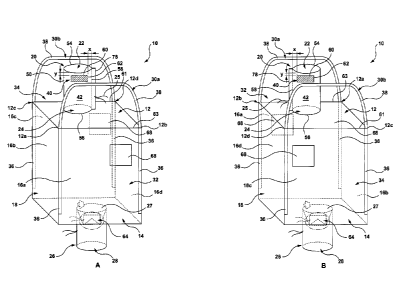
and the flexible container bag filled with the bulk material through the
filling spout using, for
example, a gravity feed. Although the filling part of the flexible container
bag can be automated
to some extent, the unfolding of the folded flexible container bags and their
engagement with the
hopper is a manual step in existing systems and is therefore a rate delimiting
step in the entire
1
13100803.1
CA 3047470 2019-06-20
filling cycle. Time loss in the filling cycle can mean less flexible container
bags filled within a
given time. Time savings during the filling cycle can translate to cost
savings.
[0005] Therefore, there is a need for flexible container bags which overcome
or reduce at least
some of the above-described problems.
SUMMARY OF THE DISCLOSURE
[0006] It is an object of the present disclosure to ameliorate at least some
of the inconveniences
present in the prior art.
[0007] From one aspect, there is provided a flexible bulk container
comprising: a top wall, a
bottom wall, and at least one sidewall, the top wall, bottom wall and the at
least one sidewall
defining an internal space; an access portion associated with the top wall for
accessing the
internal space through an open end of the access portion; and a position
marker located at a
predetermined position on the access portion for detection by a detector of a
robotic system. In
certain embodiments, the top wall has an opening and the internal space can be
accessed through
the open end of the access portion and the opening in the top wall.
[0008] In certain embodiments, the predetermined position of the position
marker is an x, y
coordinate relative to at least one reference point on the access portion. In
certain embodiments,
the predetermined position of the position marker is a distance from at least
one reference point
on the access portion in a certain direction. By position of the position
marker is meant, in
certain embodiments, the position of a part of the position marker such as a
corner, or an edge, or
a central point, for example. The at least one reference point can be on, or
along, one or more of
the open end of the access portion, a side edge of the access portion, a
longitudinal mark along a
longitudinal dimension of the access portion, an intersection of the open end
and the side edge of
the access portion, and an intersection of the open end and the longitudinal
mark of the access
portion. The position marker can be a visually detectable mark. In certain
embodiments, the
position marker has a format recognisable by the detector, and is positioned
on an outer surface
of the access portion.
2
13100803.1
CA 3047470 2019-06-20
[0009] In certain embodiments, the flexible bulk container further comprises a
removeable
insert which is sized and shaped to position the access portion, or the
position marker, at a
predetermined position relative to at least one of an upper fold edge, a lower
fold edge or side
fold edges of the flexible bulk container, when the flexible bulk container is
empty and folded
with the access portion laying on an upperfold face of the folded flexible
bulk container. In
certain embodiments, the insert comprises a head portion, and a tail portion
extending from the
head portion for spacing the access portion from the upper fold edge of the
folded flexible bulk
container, the head portion having an insert upper edge and the tail portion
being sized and
shaped for engagement with the open end of the access portion, and lateral
spacer portions
extending from the head portion, one on either side of the tail portion, for
spacing the access
portion from the side fold edges of the folded flexible bulk container when
the flexible bulk
container is empty and folded.
[0010] In certain embodiments, the access portion is a filling spout extending
from the top wall.
The position marker can be a visual mark having a format recognisable by the
detector, and can
.. be positioned on an outer surface of the filling spout. The at least one
reference point can be on
one or more of the open end of the filling spout, a side edge of the filling
spout, a longitudinal
mark along a longitudinal dimension of the filling spout, an intersection of
the open end of the
filling spout and the side edge of the filling spout, and an intersection of
the open end of the
filling spout and the longitudinal dimension of the filling spout, the x, y
coordinate indicating a
distance from the at least one reference point. The predetermined position of
the position marker
can be a distance from one or more of the open end of the filling spout, a
side edge of the filling
spout when the filling spout is folded, a longitudinal mark along the
longitudinal dimension of
the filling spout, an intersection of the open end of the filling spout and
the side edge of the
filling spout, and an intersection of the open end of the filling spout and
the longitudinal
dimension of the filling spout. In certain embodiments, the longitudinal mark
is a stitch mark
along the longitudinal dimension of the folded filling spout, the stitch mark
having a different
colour than the outer surface of the filling spout. In certain embodiments,
the stitch mark has a
contrasting colour to that of the filling spout.
[0011] In certain embodiments, the predetermined position of the position
marker is a pre-
defined distance from the open end of the filling spout, in a direction from
the open end towards
3
13100803.1
CA 3047470 2019-06-20
a base of the filling spout, and an equidistant distance from oppositely
facing side edges of an
exposed face of the filling spout when the filling spout is folded and laid
flat against an upper
fold face of the flexible bulk container. The filling spout can be folded from
its base.
[0012] In certain embodiments, the visual mark has a contrasting colour to
that of the outer
surface of the filling spout. The visual mark can be a black strip. The visual
mark can be attached
to or formed on the outer surface of the filling spout. The visual mark can be
any other colour.
The black strip can be attached to the filling spout by stitching. The black
strip can be positioned
with its longitudinal axis substantially perpendicular to the longitudinal
axis of the filling spout.
The position marker can help to position a robotic arm of a robotic system to
grip a folded
flexible bulk container at the filling spout only. In these embodiments, the
position marker
functions as a reference point for the robotic arm, which can be made to move
predetermined
distances and directions from the reference point.
[0013] In certain embodiments, at least a portion of the filling spout on
which the position
marker is located is formed from a fabric of sufficient stiffness to present a
substantially flat
upwardly facing surface when the flexible bulk container is empty and is
folded. By upwardly
facing surface is meant the surface which is exposed when the flexible bulk
container is empty
and is folded. In one embodiment, substantially the entire filling spout is
formed from a fabric of
sufficient stiffness to present a substantially flat upwardly facing surface
when the flexible bulk
container is empty and is folded.
[0014] In certain embodiments, the fabric has a weight of between about 70 to
about 200 g/m2,
about 70 to about 240 g/m2, about 75 to about 240 g/m2, about 75 to about 230
g/m2, about 75 to
about 220 g/m2, about 75 to about 210 g/m2, 75 to about 190 g/m2, about 75 to
about 180 g/m2,
about 75 to about 170 g/m2, about 75 to about 160 g/m2, about 75 to about 150
g/m2, about 75 to
about 140 g/m2, about 75 to about 135 g/m2, about 75 to about 130 g/m2, about
100 to about 150
g/m2, about 110 to about 140 g/m2, or about 135 g/m2. The fabric can be made
of a woven
material such as woven polypropylene.
[0015] In certain embodiments, the at least a portion of the filling spout on
which the position
marker is located is laminated. In one embodiment, substantially the entire
filling spout is
laminated. The entire filling spout may be laminated, with at least one layer
of a polymer such as
4
13100803.1
CA 3047470 2019-06-20
polyethylene. The lamination may have a weight of 30 g/m2. In certain
embodiments, the filling
spout is made of a polypropylene fabric having a weight of 135 g/m2 and having
a polyethylene
lamination of 30 g/m2. In certain embodiments, the combination of at least two
of the weight of
the filling spout, the weight of the lamination combination and the insert,
provides a stiffness to
the filling spout which is sufficient to maintain a degree of flatness to the
position marker for
detection by a robotic system.
[0016] In certain embodiments, the tail portion of the insert is sized and
shaped for insertion
into the open end of the filling spout. The tail portion can have a width,
defined by a distance
between two tail portion side edges, sufficient to allow it to be received in
the filling spout and
wide enough to maintain at least a portion of the filling spout substantially
flat when the filling
spout is folded, when the tail portion is received in the filling spout when
the flexible bulk
container is empty and folded. In certain embodiments, the lateral spacer
portions of the insert
are sized and shaped to position the folded filling spout substantially
centrally between the two
side fold edges of the folded flexible bulk container. In certain embodiments,
a width of the
insert is the same or slightly smaller than the distance between the side fold
edges of the folded
flexible bulk container. The insert may have an upper edge which is
substantially perpendicular
to one or more of the tail side edges or insert side edges of the spacer
portions. The insert may
have an upper edge which is substantially perpendicular to a longitudinal axis
of one or more of
the tail portion or the lateral spacer portion.
[0017] In certain embodiments, the insert further comprises slots extending
from the insert
upper edge towards the tail portion for receiving at least one folded portion
of the folded flexible
bulk container. In certain embodiments, the insert has holes defined in the
head portion. In
certain embodiments, the insert has a flap on each lateral spacing portion for
engagement with at
least one folded portion of the folded flexible bulk container.
[0018] From another aspect, there is provided a flexible bulk container
comprising: a top wall, a
bottom wall, and at least one sidewall, the top wall, bottom wall and the at
least one sidewall
defining an internal space; a filling spout extending from the top wall and
having one open end
in fluid communication with an opening in the top wall for accessing the
internal space through
5
13100803 1
CA 3047470 2019-06-20
the filling spout, and a position marker detectable by a detector of a robotic
system, the position
marker being located at a predetermined distance from the open end of the
filling spout.
[0019] From yet another aspect, there is provided a flexible bulk container
comprising: a top
wall, a bottom wall, and at least one sidewall, the top wall, bottom wall and
the at least one
sidewall defining an internal space; a filling spout extending from the top
wall and having one
open end in fluid communication with an opening in the top wall for accessing
the internal space
through the filling spout, and a position marker on an outer surface of the
filling spout, the
position marker being located on an upwardly facing folded surface of the
filling spout when the
flexible bulk container is folded, the position marker being detectable by a
detector of a robotic
system. In certain embodiments, the predetermined position of the position
marker is a
predefined distance from the open end of the filling spout, in a direction
from the open end
towards a base of the filling spout, and equidistant from oppositely facing
side edges of the
filling spout when the filling spout is folded and laid flat against an upper
fold face of the
flexible bulk container.
.. [0020] In certain embodiments, the flexible bulk container comprises a
removeable insert which
is sized and shaped to position the filling spout, or the position marker, at
a predetermined
position relative to at least one of an upper fold edge, a lower fold edge or
side fold edges of a
folded form of the flexible bulk container, the folded form comprising the
flexible bulk container
folded whilst empty with the filling spout laying on an upper fold face of the
folded flexible bulk
container.
[0021] In certain embodiments, the insert comprises a head portion having an
insert upper edge,
a tail portion extending from the head portion for insertion into the open end
of the filling spout,
and lateral spacer portions extending from the head portion, one on either
side of the tail portion.
[0022] From another aspect, there is provided a stack of flexible bulk
containers, the stack
comprising a plurality of flexible bulk containers, in accordance with any of
the above-described
embodiments, each flexible bulk container having a folded form comprising an
upper fold edge,
a lower fold edge and two side fold edges, with the filling spout folded and
laying on an upper
fold face of the folded flexible bulk container. The filling spout may have a
substantially
cylindrical form and is folded flat along a longitudinal axis. In certain
embodiments, the position
6
13100803.1
CA 3047470 2019-06-20
marker on the filling spout faces outwardly. Each one of the flexible bulk
containers of the stack
has a lower fold face and the flexible bulk containers of the stack can be
stacked such that the
lower fold face of one flexible bulk container lies against an upper fold face
of an adjacent
flexible bulk container. Each flexible bulk container of the stack includes an
insert, according to
any of the embodiments described herein, the tail portion of the insert
extending into the open
end of the filling spout, at least a portion of the head portion of the insert
extending from the
upper fold edge, and the lateral spacer portions lying on either side of the
filling spout on the
upper fold face of the folded flexible bulk container. In certain embodiments,
folded flexible
bulk containers are assembled to form the stack such that the stack is
substantially cuboid in
.. shape.
[0023] In certain embodiments, the flexible bulk containers are stacked in a
head-to-tail
configuration. In this regard, the upper fold face of each one of the flexible
bulk container of the
stack may be oriented at approximately 1800 relative to an adjacent one of the
flexible bulk
container of the stack. In other words, the stack of flexible bulk containers
can comprise one
folded flexible bulk container layered on top of another folded flexible bulk
container, the upper
fold face of each of the folded flexible bulk containers facing in the same
direction (e.g.
upwardly). Expressed in a different way, the stack can comprise a first folded
flexible bulk
container having a first orientation, and stacked on top of an adjacent second
folded flexible bulk
container having a second orientation, the first and second orientations being
substantially 180
to each other.
[0024] In certain embodiments, the stack further comprises a pallet on which
the plurality of
flexible bulk containers are stacked. The stack may further comprise inner
strap(s) around the
plurality of flexible bulk containers. The inner strap(s) may contribute to
maintaining the
plurality of flexible bulk containers in a compressed form. In certain
embodiments, the stack
comprises a rack positioned over an upper-most folded flexible bulk container.
Outer strap(s)
may connect the rack to the pallet. The rack may comprise guides extending
across a top surface
of the rack for receiving a portion of the outer strap(s), which may help to
retain the position of
the outer strap(s). The guides may comprise a pair of parallel rails. In
certain embodiments, the
stack comprises one or more of a lower cover extending from the pallet
upwardly (from a
lowermost folded flexible bulk container of the stack to the uppermost folded
flexible bulk
7
13100803.1
CA 3047470 2019-06-20
container of the stack), and an upper cover extending from the uppermost
folded flexible bulk
container of the stack downwardly. The upper cover may be positioned beneath
the rack. The
outer strap(s) may extend over the one or more of the lower cover and the
upper cover.
[0025] From another aspect, there is provided an insert for use with a
flexible bulk container,
the insert comprising: a head portion and a tail portion extending therefrom,
the head portion
having an insert upper edge and the tail portion being sized and shaped for
engagement with an
open end of a filling spout, and lateral spacer portions extending from the
head portion, one on
either side of the tail portion. The tail portion has a width, defined by a
distance between two tail
portion side edges, sufficient to allow it to be received in the filling spout
and wide enough to
maintain at least a portion of the filling spout substantially flat, when the
tail portion is received
in the filling spout when the flexible bulk container is empty and folded. The
lateral spacer
portions can be sized and shaped to position the folded filling spout
substantially centrally
between two side fold edges of the folded flexible bulk container. In certain
embodiments, a
width of the insert is the same or slightly smaller than the distance between
the side fold edges of
the folded flexible bulk container. The insert has an upper edge which can be
substantially
perpendicular to a longitudinal axis of one or both of the tail portion or the
lateral spacer
portions.
[0026] In certain embodiments, the insert further comprises slots extending
from the insert
upper edge towards the tail portion for receiving at least one folded portion
of the folded flexible
bulk container. This embodiment of insert can be used with flexible bulk
containers having a
length which when folded in half exceeds a dimension of a pallet on which the
folded flexible
bulk container will be stored.
[0027] In certain embodiments, the insert has holes defined in the head
portion. In certain
embodiments, the insert has a flap on each lateral spacing portion for
engagement with at least
one folded portion of the folded flexible bulk container.
[0028] From a further aspect, there is provided a folded flexible bulk
container, according to
any of the embodiments described herein, the folded flexible bulk container
comprising an upper
fold face, an upper fold edge, a lower fold edge and a side fold edges,
wherein the filling spout is
folded along a longitudinal length and laid against the upper fold edge. In
certain embodiments, a
8
13100803.1
CA 3047470 2019-06-20
fold of the filling spout is substantially parallel to the longitudinal marker
of the filling spout. In
certain embodiments, the position marker of the folding spout is upwardly
facing when the
filling spout is folded onto the upper fold face. In certain embodiments, the
folded flexible bulk
container includes the insert with the tail portion extending into the filling
spout, and the head
portion protruding from the filling spout outer edge.
[0029] From a further aspect, there is provided a robotic system for unpacking
of a stack of
folded flexible bulk containers, according to any of the embodiments described
herein, the
robotic system comprising a detector for detecting a position of the position
marker of an
uppermost folded flexible bulk container of the stack of folded flexible bulk
containers, a
processor in communication with the detector for controlling a first robotic
arm for gripping the
uppermost folded flexible bulk container of the stack, and a second robotic
arm for gripping and
removing the insert of the uppermost folded flexible bulk container of the
stack. In certain
embodiments, the processor is arranged to store instructions on how to move
the first and second
robotic arms relative to the detected position marker. The robotic system is
arranged to engage
the unpacked uppermost flexible bulk container with a filling system, such as
a hopper.
[0030] From a yet further aspect, there is provided a method for unpacking a
stack of folded
flexible bulk containers, according to any of the embodiments described
herein, the method
comprising providing a stack of folded flexible bulk containers, detecting a
position of the
position marker of an uppermost folded flexible bulk container of the stack of
folded flexible
bulk containers, and providing the position to a processor in communication
with the detector,
the processor controlling a first robotic arm for gripping the uppermost
folded flexible bulk
container of the stack at the filling spout and lifting the uppermost folded
flexible bulk container
away from the stack, and a second robotic arm for gripping and removing the
insert of the
uppermost folded flexible bulk container of the stack. In certain embodiments,
the first robotic
arm is arranged to grip the filling spout at a position which is spaced from
the position marker
towards the base of the filling spout. In certain embodiments, the first
robotic arm grips the
filling spout clear of the insert, so that the insert is not gripped. This can
help with the removal of
the insert by the second robotic arm.
9
13100803.1
CA 3047470 2019-06-20
[0031] By means of certain aspects and embodiments, an automated unpacking of
flexible bulk
containers is provided. By means of certain aspects and embodiments of the
present disclosure,
an automated attachment of flexible bulk containers to hoppers for filling is
provided.
Automation of at least the unpacking of the flexible container bags and their
attachment to a
hopper can provide time savings, enabling more flexible container bags to be
unpacked from a
stack of flexible container bags for attachment to a hopper, when compared
with a manual
method. This can therefore translate to costs savings. The automation of the
unpacking according
to certain embodiments of the present disclosure can also limit the exposure
of human workers to
certain dangers and work-related injuries.
[0032] From a yet further aspect, there is provided a computer program
comprising instructions
for causing the robotic system to grip and unpack the uppermost folded
flexible bulk container of
the stack, according to any of the embodiments as described above.
[0033] It must be noted that, as used in this specification and the appended
claims, the singular
form "a", "an" and "the" include plural referents unless the context clearly
dictates otherwise.
[0034] As used herein, the term "about" in the context of a given value or
range refers to a value
or range that is within 20%, preferably within 10%, and more preferably within
5% of the given
value or range.
[0035] As used herein, the term "and/or" is to be taken as specific disclosure
of each of the two
specified features or components with or without the other. For example "A
and/or B" is to be
taken as specific disclosure of each of (i) A, (ii) B and (iii) A and B, just
as if each is set out
individually herein.
BRIEF DESCRIPTION OF DRAWINGS
[0036] Further aspects and advantages of the present invention will become
better understood
with reference to the description in association with the following in which:
[0037] Figure 1A is a perspective view of flexible container bag, in an
unfolded state, when
viewed from a front end, according to an embodiment of the present disclosure;
13100803.1
CA 3047470 2019-06-20
[0038] Figure 1B is a perspective view of the flexible container bag of 1A
when viewed from a
back end, according to an embodiment of the present disclosure;
[0039] Figure 2A is the flexible container bag of Figure 1, in a folded state,
and when viewed
from an upper fold face of the folded flexible container bag, according to an
embodiment of the
present disclosure;
[0040] Figure 2B is the folded flexible container bag of Figure 2A when viewed
from an upper
fold end of the folded flexible container bag, according to an embodiment of
the present
disclosure;
[0041] Figure 3 is the folded flexible container bag of Figure 2A including an
insert, according
to an embodiment of the present disclosure;
[0042] Figures 4A, 4B, and 4C illustrate the insert of Figure 3, according to
different
embodiments of the present disclosure;
[0043] Figure 5 illustrates a plurality of the folded container bags of Figure
3 including the
respective inserts, stacked on a pallet, according to an embodiment of the
present disclosure;
[0044] Figure 6 illustrates a robotic system for automated unfolding of the
flexible container bag
of Figure 3, according to an embodiment of the present disclosure; and
[0045] Figure 7 illustrates the unfolded flexible container bag of Figure 6
and engaged with a
filling tube of a hopper.
DETAILED DESCRIPTION
[0046] The present disclosure is not limited in its application to the details
of construction and
the arrangement of components set forth in the following description or
illustrated in the
11
13100803.1
CA 3047470 2019-06-20
drawings. The disclosure is capable of other embodiments and of being
practiced or of being
carried out in various ways. Also, the phraseology and terminology used herein
is for the purpose
of description and should not be regarded as limiting. The use of "including",
"comprising", or
"having", "containing", "involving" and variations thereof herein, is meant to
encompass the
items listed thereafter as well as, optionally, additional items. In the
following description, the
same numerical references refer to similar elements.
[0047] Broadly, there is provided a flexible bulk container which is suitable
for automated
unfolding. Specifically, the flexible bulk container detection is suitable for
handling by a robotic
system whilst in a folded state on a stack of flexible bulk containers. In the
embodiment
described below, the robotic system is arranged to lift or unpack an uppermost
flexible bulk
container from the stack of folded bulk containers, for engagement with a
filling system for
filling the flexible bulk container with bulk material.
[0048] Referring initially to Figure 1, according to one embodiment, there is
provided a flexible
bulk container 10 having a top wall 12, a bottom wall 14, and sidewalls 16a,
16b, 16c and 16d
defining a generally cuboidal-shaped body. The top wall 12, bottom wall 14 and
the sidewalls
16a, 16b, 16c, and 16d define an internal space 18. The top wall 12 has an
access portion 20
associated therewith, in the form of a filling spout 20. The internal space 18
can be accessed
through an open end 22 of the filling spout 20 and a top wall opening 24
defined in the top wall
12. A tie 25 is provided in conventional manner to close the filling spout 20.
The bottom wall 14
has a discharge spout 26 extending from the bottom wall 14 and through which
bulk material
(not shown) stored in the flexible bulk container 10 can be discharged through
an opening 27 in
the bottom wall 14 and an open end 28 of the discharge spout 26. In
alternative embodiments,
the flexible bulk container 10 has a cylindrical shaped body and a single
cylindrical side wall
instead of the side walls 16a, 16b, 16c and 16d. In other alternative
embodiments, the discharge
spout 26 is omitted. In other embodiments, a closure mechanism different than
those illustrated
for the filling spout 20 and/or the discharge spout 26 is provided.
[0049] Two lifting loops 30a, 30b are provided extending from the top wall 12
of the flexible
bulk container 10. One lifting loop 30a extends between adjacent corners 12a,
12b of the top wall
12
13100803.1
CA 3047470 2019-06-20
12 along a front end 32 of the flexible bulk container 10. The other lifting
loop 30b extends
between adjacent corners 12c, 12d of the top wall 12 along a back end 34 of
the flexible bulk
container 10. As can be seen in Figure 1, an end portion 36 of each of the
lifting loops 30a, 30b
are attached to, or integral with, the side walls 16a, 16b, 16c and 16d. A
handle portion 38,
between two end portions 36, of each of the lifting loops 30a, 30b extend from
the side walls
16a, 16b, 16c and 16d and are of equal length. In this embodiment, the handle
portion 38 of each
lifting loop is 115 cm. These types of lifting loops are referred to in the
art as 'Stevedore straps'.
In other embodiments, the lifting loops 30a, 30b can be of any other suitable
length. In other
embodiments, the lifting loops 30a, 30b can be of any other configuration such
as four separate
loops extending from each of the corners 12a, 12b, 12c, and 12d, a single
diagonal loop, or any
other number or configuration of loop or strap.
[0050] The filling spout 20 has a generally cylindrical form and includes a
position marker 40
located at a predetermined position on an outer surface 42 of the filling
spout 20. As illustrated in
Figure 1A and Figure 1B, the position marker is on the back end 34 of the
flexible bulk container
10. The position marker 40 is arranged to be detectable by a detector 44 of a
robotic system 46 at
a filling site (Figure 6). In this embodiment, the detector 44 is an optic
eye, or any other
detection system, connectable to a processor 48 which is arranged to control
robotic arms 50, 52
(also referred to as first robotic arm 50, and second robotic arm 52).
[0051] The position marker 40 is a machine detectable mark. In this
embodiment, the position
marker 40 is visually detectable by the detector 44 of the robotic system 46
for automated
unpacking and filling. The position marker 40 is a strip having a colour
(black) which is in
contrast to the outer surface 42 (white) of the filling spout 20. Other
contrasting colour
combinations are possible. The position marker 40 is a separate piece of
material which is
attached to the outer surface 42 of the filling spout 20 by stitching. In this
embodiment, the
position marker 40 is a rectangular piece of material made of polypropylene,
but can be made of
any other suitable material. In other embodiments, the position marker 40 is
attached to the
filling spout 20 in any other way such as by laminating, gluing, heat bonding,
painting, dyeing or
by using attachment means such as rivets, staples, bolts etc. In other
embodiments, the position
marker 40 is formed integrally with the filling spout 20.
13
13100803.1
CA 3047470 2019-06-20
[0052] In other embodiments, the visually detectable position marker 40 has a
different shape or
colour than the rectangular shape shown in Figures 1-3 and 6, such as square,
triangular, circular,
or comprises a patterned configuration such as a bar code, or the like. In
other embodiments, the
.. position marker 40 is a mark which is detectable by another electromagnetic
signal detector, such
as radio signal detector, an infrared detector, x-ray detector, or the like.
In other embodiments,
the position marker 40 is an active tag and has a transmitter to emit signals.
In other
embodiments, the position marker 40 is a passive tag and is arranged to
reflect signals to the
detector 44. In one embodiment, the position marker 40 is a RFID tag.
[0053] The predetermined position of the position marker 40 on the outer
surface 42 of the
filling spout 20 is a distance from two reference points on the filling spout
20, as an x, y
coordinate for example. In this respect, the filling spout 20 has a
substantially cylindrical body
50 having an outer edge 54 defining the open end 22. The filling spout is 20
is tapered towards a
base 56 of the filling spout 20. The y coordinate is a predetermined distance
from the filling
spout outer edge 54 in a direction towards the base 56 of the filling spout
20. A longitudinal
marker 58, extending in a direction along the length of the filling spout 20
from the filling spout
outer edge 54 towards the base 56, represents another reference point. The x
coordinate is a
predetermined distance from the longitudinal marker 58 in a radial direction
around the
.. cylindrical body of the filling spout 20. The longitudinal marker 58 is a
stitch line. In this
embodiment, the cylindrical form of the body is created by folding a
rectangular blank of
material on itself and stitching along the stitch line. The stitch line has a
contrasting colour to
that of the outer surface 42 of the filling spout 20. The predetermined
position also defines an
orientation of the position marker 40, such as the position marker being
aligned along its length
with the filling spout outer edge 54. In this embodiment, the distance "y"
from the filling spout
outer edge 54 to the position marker is about 13 to about 16 cm. In other
words, an upper edge
60 of the position marker 40 is positioned about 13 to about 16 cm from the
filling spout outer
edge 54. In this embodiment, the position marker 40 is 5x40 cm, although other
shapes and
dimensions of the position marker 40 are possible.
14
13100803.1
CA 3047470 2019-06-20
[0054] The longitudinal marker 58 also assists in positioning of the filling
spout 20 relative to
the top wall 12, when forming the flexible bulk container 10, as well as
helping with the
positioning of the filling spout 20 during folding of the flexible bulk
container 10. In this respect,
the filling spout 20 is positioned substantially centrally on the top wall 12
when folded. The
flexible bulk container 10 is formed such that a distance from the
longitudinal marker 58 to an
upper edge 61 of the top wall 12 is equidistant to a distance from the
longitudinal marker 58 to a
lower edge 63 of the top wall 12. In this embodiment, the distance is about 55
cm. In other
embodiments, the predetermined position of the position marker 40 can be
defined in any other
way, for example, as a distance from one or more reference points on the
filling spout 20 or on
the flexible bulk container 10. In one embodiment, the reference point is an
intersection of the
longitudinal marker 58 and the outer edge 54, and the predetermined position
is a distance from
the reference point, which can be an x, y distance.
[0055] The discharge spout 26 of the flexible bulk container 10 has a
conventional form, and can
be closed and opened using a closing system 64 comprising conventional means
such as flaps
and ties, as known to persons skilled in the art, and so will not be described
further.
[0056] The flexible bulk container 10 is made from a material having
mechanical properties
which allow the folding of the flexible bulk container 10, and strong enough
to store and lift
material such as grain. In this embodiment, the flexible bulk container 10 is
made from a woven
polypropylene, using for example a Sulzer weave. Alternatively, the flexible
bulk container 10
can be made from any other material suited for the intended end use of the
flexible bulk
container 10, or from any other weave such as flat weave/ flat fabric, or
circular weave/ circular
fabric.
[0057] Flexible bulk containers are typically provided to filling sites as a
stack 65 of folded
flexible bulk containers 10, positioned one on top of another, on a pallet 66
(Figure 5). Unlike in
systems of the prior art, in the present disclosure, embodiments of the
present flexible bulk
container 10, such as described above, and its manner of folding, in certain
embodiments, allows
a robotic system, such as the robotic system 46, to automatically unpack the
uppermost folded
flexible bulk container 10 in the stack 65 of folded flexible bulk containers
10 and position them
13100803.1
CA 3047470 2019-06-20
for engagement with a filling hose 67 of a hopper 69 (Figure 7) for filling
with the bulk material.
In certain embodiments, the flexible bulk container 10 allows for automatic
unpacking of a stack
65 of flexible bulk containers 10 using the robotic system 46.
.. [0058] Detection of the location of the position marker 40 on the flexible
bulk container 10
provides information to the robotic system 46 to allow accurate positioning of
the robotic arms
50, 52 for lifting the flexible bulk container 10 from the stack 65 of
flexible bulk containers 10.
In this respect, the flexible bulk container 10 is arranged to be folded in
such a way as to lay flat
the filling spout 20 on the side wall 16a of the flexible bulk container 10
when the flexible bulk
container is empty 10 and folded. The filling spout 20 and position marker 40
are arranged to
present a substantially flat upwardly facing outer surface 42 in order to
minimise or eliminate the
distortion of the visual appearance of the position marker 40. It will be
appreciated that creases
or folds of the position marker 40 or the outer surface 42 of the filling
spout 20 to which the
position marker is attached 40 may hinder the accurate positioning of the
robotic arms 50, 52 due
to an inaccurate detection of the location of the position marker 40 by the
detector 44.
[0059] In this respect, the filling spout 20 comprises a material having a
sufficient stiffness to
present a substantially flat upwardly facing outer surface 42 when the
flexible bulk container 10
is empty and is folded. In this embodiment, this is achieved through a
combination of fabric
weight and lamination. The inventors have found that by forming the filling
spout 20 from a
material having a higher stiffness than the conventional 70 g/m2, and by
laminating, it is possible
to minimise or eliminate creases or wrinkles in the position marker 40, and/or
the surrounding
material of the filling spout 20, whilst balancing this functionality with
production costs (the
thicker the material used, the higher cost per unit of flexible bulk
container).
[0060] The weight of the fabric of the filling spout 20 is more than the
weight of the fabric of the
discharge spout 26. The weight of the fabric of the filling spout 20 is less
than the weight of the
fabric of the side walls 16a, 16b, 16c and 16d, and the bottom wall 14 of the
flexible bulk
container 10. In this embodiment, the weight of the fabric of the discharge
spout 26 is 70 g/m2,
and the weight of the fabric of the side walls 16a, 16b, 16c and 16d of the
flexible bulk container
is 200 g/m2. The weight of the fabric of the filling spout 20 is between about
70 to about 200
16
13100803.1
CA 3047470 2019-06-20
g/m2, about 70 to about 240 g/m2, about 75 to about 240 g/m2, about 75 to
about 230 g/m2, about
75 to about 220 g/m2, about 75 to about 210 g/m2, about 75 to about 190 g/m2,
about 75 to about
180 g/m2, about 75 to about 170 g/m2, about 75 to about 160 g/m2, about 75 to
about 150 g/m2,
about 75 to about 140 g/m2, about 75 to about 135 g/m2, about 75 to about 130
g,/m2, about 100
to about 150 g/m2, about 110 to about 140 g/m2. Specifically, in this
embodiment, the weight of
the fabric of the filling spout 20 is about 135 g/m2. The top wall has a
weight of about 70 g/m2.
[0061] The lamination is a layer of transparent material on the outer surface
of the filling spout
20. In this embodiment, the lamination is a polyethylene layer. In other
embodiments, other
suitable materials can be used as the laminate. The weight of the lamination
is about 30 g/m2.
[0062] Pockets 68 (Figure 1) are provided on two oppositely facing side walls
16a, 16c of the
flexible bulk container 10 for housing labels or documentation. The pockets 68
are
polypropylene sheets which are laminated on an outer surface and attached to
the respective side
wall 16a, 16c by stitching. When viewed from the front end 32 (Figure 1A), one
of the pockets
68 is positioned on the side wall 16a at the front end 32 of the flexible bulk
container 10, and the
other pocket 68 is positioned on the side wall 16c at the back end 34 of the
flexible bulk
container 10. The pockets 68 are both positioned to one side of the filling
spout 20. As seen in
Figure 1B, the pockets are positioned on the left side of the longitudinal
marker 58 side of the
filling spout 20 and the tie 25. This configuration can provide ease of
folding, as will be
described below. In other embodiments, the flexible bulk container 10 includes
only one pocket
68 or no pockets. The pockets can be made of any other material.
[0063] Referring now to Figures 2A, 2B and 3, in which the flexible bulk
container 10 of Figure
1 is illustrated in a folded state. The folded flexible bulk container 10 has
an upper fold face 70,
an upper fold edge 72, a lower fold edge 74 and two oppositely facing side
fold edges 76. The
flexible bulk container 10 is folded such that the filling spout 20 is folded
flat on the upper fold
face 70 with the position marker 40 facing upwardly. The flexible bulk
container 10 is folded
such that the side wall 16a becomes the upper fold face 70 in the folded
flexible bulk container
10. In other words, the filling spout 20 is folded from the filling spout base
24 towards the
bottom wall 14 and laid flat against the side wall 16a such that the
longitudinal marker 58
17
13100803.1
CA 3047470 2019-06-20
extends along a filling spout side edge 78. The lifting loops 30a, 30b are
positioned one above
the folded filling spout 20, and one beneath the folded filling spout 20. As
best seen in Figure 2B
showing the folded flexible bulk container 10 when viewed from an upper fold
end, the side wall
16a lies against the side wall 16c, with the side walls 16b, 16d and the
bottom wall 14, folded
inwardly and sandwiched between side walls 16a and 16c.
[0064] The flexible bulk container 10 is folded so that the upper fold face 70
is dimensioned to
fit onto the pallet 66, or have folded dimensions less than a surface area of
the pallet (Figure 5).
In this embodiment, a standard pallet size is about 100 x 120 cm, and so the
upper and lower fold
edges 72, 74 and side fold edges are about 116 to about 120 cm and about 96 to
about 100 cm, or
about 118 cm and 98 cm, respectively. The folded flexible bulk containers 10
are stacked, one on
top of one another, with the upper fold face 70 and the position marker 40
facing upwardly on
the pallet 66. In order to achieve a more efficient stacking, each folded
flexible bulk container 10
in the stack 65 is oriented at approximately 180 relative to an adjacent
folded flexible bulk
container 10 in the stack 65, i.e. a folded flexible bulk container
immediately above or below the
flexible bulk container 10. Each one of the flexible bulk containers 10 of the
stack 65 has a lower
fold face and the flexible bulk containers 10 of the stack 65 are stacked such
that the lower fold
face of one flexible bulk container 10 lies against the upper fold face 70 of
an adjacent flexible
bulk container 10. In alternative embodiments, each folded flexible bulk
container 10 in the stack
65 is oriented at approximately 90 , instead of 180 , relative to an adjacent
folded flexible bulk
container 10 in the stack 65.
[0065] For the accurate positioning of the robotic arms 50, 52 on the
uppermost folded flexible
bulk container 10 of the stack 65, in certain embodiments, it is desired for
the position marker 40
to be consistently positioned with respect to the side fold edges 76 and the
upper fold edge 72,
and to maintain this position during stacking of the folded flexible bulk
containers 10. In this
respect an insert 80 is provided (Figures 3, 4 and 6) which is sized and
shaped to position and
maintain the folded filling spout 20 at a predetermined position relative to
the side fold edges 76
and the upper fold edge 72 of the flexible bulk container 10. The insert 80 is
removeably
positionable in the folded flexible bulk container 10. In use, the insert 80
will be discarded by the
robotic system 46 once the robotic arm 50 has correctly gripped the uppermost
folded flexible
18
13100803.1
CA 3047470 2019-06-20
bulk container 10 from the stack 65 of flexible bulk containers 10 and removed
it from the stack
65. The insert 80 is made of cardboard. In other embodiments, the insert 80 is
re-usable and
made of a polymer such as a polyethylene, or made of a metal alloy such as an
aluminium alloy,
or comprises any other metal or polymer sheet. The insert 80 is made of a
material of sufficient
stiffness to avoid folding when inserted in the filling spout 20.
[0066] The insert 80 comprises a head portion 82 extending between an insert
upper edge 84 and
insert side edges 86. Lateral spacer portions 88 extend from the head portion
82 along each of the
insert side edges 86. A tail portion 90 also extends from the head portion 82,
between the two
lateral spacer portions 88, and is arranged to be received in the open end 22
of the filling spout
20. A longitudinal axis of the lateral spacer portions 88 and/or the tail
portion 90 is substantially
perpendicular to a longitudinal axis of the head portion 82. The two lateral
spacer portions 88
have the same width as each other and are arranged to space the filling spout
20 equidistantly
from the side fold edges 76 of the folded flexible bulk container 10 when the
flexible bulk
container 10 is empty and folded. In this respect, each lateral spacer portion
88 has the same
width.
[0067] The tail portion 90 is sized and shaped for insertion into the folded
filling spout 20. The
tail portion 90 has a width, defined by a distance between two tail portion
side edges 91a, 91b,
sufficient to allow it to be received in the filling spout 20 and wide enough
to maintain at least a
portion of the filling spout 20 substantially flat when the filling spout 20
is folded, with the tail
portion 90 received in the filling spout 20 when the flexible bulk container
10 is empty and
folded. The width of the insert 80 is the same or slightly smaller than the
distance between the
side fold edges 76 of the folded flexible bulk container 10. The insert 80
upper edge 84 is
substantially perpendicular to one or more of the tail 90 side edges or the
insert side edges 86.
[0068] In this embodiment, the flexible bulk container has body dimensions of
about
110x110x112 cm and the filling spout 20 has a diameter of about 41 cm, and a
height of about 61
cm. A distal end of the tail portion 90 has a pronged or concave
configuration. Other distal end
cut-out shapes and configurations are possible for reducing a total weight of
the insert. A width
of the insert 80 is the same or slightly smaller than the distance between the
side fold edges 76 of
19
13100803.1
CA 3047470 2019-06-20
the folded flexible bulk container 10. In this embodiment, the width of the
tail portion 90 of the
insert 80 is about 60 cm. It will be appreciated that the size and dimensions
of the insert 80 can
vary from the figures provided herein, and in accordance with the size and
dimensions of the
flexible bulk container 10 with which it will be used.
[0069] As seen in Figure 3, when the insert 80 is placed with the tail portion
90 inserted into the
open end 22 of the filling spout 20, the head portion 82 and the lateral
spacer portions 88 lie on
the upper fold face 70 (side wall 16a). The outer edge 54 of the filling spout
20 at the filling
spout side edges 78 abuts the insert 80 at the junctions where each one of the
lateral spacer
portions 88 meet the tail portion 90. The head portion 82 protrudes away from
the outer edge 54
to facilitate the gripping of the insert 80 and the head portion 82. In use,
the insert 80 will be
gripped and discarded by the robotic arm 52, once the flexible bulk container
10 has been
removed from the stack 65 of flexible bulk containers 10. The insert upper
edge 84 may be
substantially flush with the upper fold edge 72. This depends on the size and
the dimensions of
the flexible bulk container 10.
[0070] In Figure 4A, there is shown an embodiment of the insert 80 which
differs from that of
Figure 3, in that four circular openings 92 are provided in the head portion
82 and aligned with
respect to each other in a direction generally parallel to, and along, the
insert upper edge 84. The
openings can reduce the weight of the insert 80, and hence the total weight of
the stacked flexible
bulk containers 10 even further. In certain embodiments, the openings 92 can
also facilitate flat
stacking of the folded flexible bulk containers 10. The insert 80 of Figure 4A
can be used with
any size of flexible bulk container 10 and filling spout 20, such as those
with dimensions of
about 110x110x72 cm and about 110x110x158 cm.
[0071] In Figure 4B, there is shown an embodiment of the insert 80 which
differs from that of
Figure 4A, in that instead of the four circular openings 92, there are
provided two slots 94
extending transversely from the insert upper edge 84 towards the tail portion
90. In certain
embodiments, these inserts 80 are particularly well suited for flexible bulk
containers 10 having
a longer length of body, such as flexible bulk containers with the dimensions
110x110x112 cm,
or longer than 112 cm. When this larger flexible bulk container 10 is folded
as before with the
13100803.1
CA 3047470 2019-06-20
filling spout 20 laying on the upper fold face 70 (corresponding to the side
wall 16a), the upper
fold face 70 is longer than a standard pallet size. Therefore, to facilitate
the folded flexible bulk
container 10 fitting on the standard pallet 66, the additional length is
folded over the insert upper
edge 84 and inserted into the slots 94 to hold them in position. In this
embodiment, the insert 80
can therefore provide an additional functionality of sizing the folded
flexible bulk container 10 to
fit on a desired size of pallet 66.
[0072] In Figure 4C, there is shown an embodiment of the insert 80 which
differs from that of
Figure 4A, in that the insert 80 is adapted to be used with flexible bulk
containers 10 having a
shorter length of body, which when folded is less than the dimensions of the
pallet 66. For
example, the insert 80 of Figure 4C can be used with flexible bulk containers
10 with the
dimensions of about 110x110x59 cm. When this smaller size flexible bulk
container 10 is folded
as before with the filling spout 20 laying on the upper fold face 70
(corresponding to the side
wall 16a), the upper fold face 70 falls short of the pallet 66 size.
Therefore, the head portion 82
is sized to extend the dimensions of the upper fold face 70 of the folded
flexible bulk container
10 to fit the pallet 66. Flaps 96 are provided on the lateral spacer portions
88, to engage with the
upper fold edge 72.
[0073] For convenient transportation, the stack 65 of folded flexible bulk
containers 10 can be
prepared as a package 100 (Figure 5). The package 100 comprises a plurality of
folded flexible
bulk containers 10 stacked in a head-to-tail configuration (each folded
flexible bulk container 10
is oriented approximately 180 with respect to each adjacent folded flexible
bulk container 10).
In other words, each folded flexible bulk container 10 of the stack 65 has an
orientation, the
orientation of two adjacent folded flexible bulk containers 10 being
approximately 180 relative
to each other. In alternative embodiments, the orientation of consecutive
folded flexible bulk
containers is about 90 . A lower cover 102 sits on the pallet 66 and houses a
number of lower-
most folded flexible bulk containers 10. The lower cover 102 has a base and
four sides extending
from the base. In this embodiment, the sides extend at least partially
upwardly from the base, for
example at a height of approximately 35 cm. An upper cover 104 covers the
folded flexible bulk
containers 10 and extends from the upper-most folded flexible bulk container
10 towards the
lower-most folded flexible bulk container 10. The upper cover 104 has a roof
and four sides
21
13100803.1
CA 3047470 2019-06-20
extending from the roof. The upper cover sides extend at least partially
downwardly from the
uppermost folded flexible bulk container. In this embodiment, the height of
the upper cover sides
are sufficient to cover the entire stack 65 including overlapping with at
least a portion of the
lower cover 102 sides. A rack 106 is positioned over the upper-most folded
flexible bulk
container 10 and the upper cover 100. The pallet 66 is connected to the rack
106 by outer straps
108. The pallet 66 and the rack 106 sandwich the stack 65 of folded flexible
bulk containers. It
will be appreciated that the tightness of the inner straps and/or the outer
straps 108 are selected
so as not to substantially disturb the shape or form of the folded flexible
bulk containers.
[0074] This package 100 configuration, which is essentially a wrapped stack
65, can avoid or
minimise damage to the folded flexible bulk containers 100 in the stack 65.
For example, the
outer straps 108 do not directly touch the folded flexible bulk containers 10.
Also, the rack 106
can help to keep the folded flexible bulk containers in their compressed
and/or flattened form.
An outer cover (not shown) with labelling (not shown), is provided over the
rack 106 leaving
only a portion of the pallet 66 exposed for engagement with a forklift of a
forklift truck (not
shown) to transport the stack 65. Any one or more of the lower cover 102, the
upper cover 104 or
the outer cover are made from a polymer sheeting such as polyethylene or
polypropylene. The
pallet 66 and the rack 106 are made of wood. The rack has guides 110 extending
across the rack
106 for retaining a position of the outer straps 108. The guides comprise
channels extending
across the rack for receiving at least a portion of the outer straps. As best
seen in Figure 5, in this
embodiment, three straps are provided around the pallet 66 and the rack 106
sandwiching the
stack 65. In other embodiments, the pallet 66, the rack 106, the lower cover
102, the upper cover
104 or the outer cover may be made of other suitable materials. Any one or
more of the lower
cover 102, the upper cover 104 or the outer cover may be omitted.
[0075] The package 100 is formed as follows. Once the flexible bulk container
10 has been
folded with the insert 80 in position, it is placed into a pressing machine
(not shown), and other
folded flexible bulk containers 10 are placed individually one on top of each
other to form a
stack 65 of folded flexible bulk containers 10. As mentioned earlier, the
orientation of each
folded flexible bulk container 10 is at 180 to an adjacent folded flexible
bulk container 10. In
other words, each folded flexible bulk container 10 is alternately oriented
relative to an adjacent
22
13100803.1
CA 3047470 2019-06-20
folded flexible bulk container 10 in the stack 65. The stack 65 of folded
flexible bulk containers
is then compressed to reduce a height of the stack 65. In this embodiment, the
stack 65
comprises one hundred and twenty five (125) folded flexible bulk containers
10, which are
compressed by the pressing machine in batches of 30-35 folded flexible bulk
containers 10. In
5 other embodiments, the stack 65 comprises more or less than one hundred
and twenty five (125)
folded flexible bulk containers 10. The insert 80 used with each folded
flexible bulk container 10
can help to maintain the position of the position marker 40 relative to the
upper fold face 70, as
well as minimising or avoiding creases in the position marker 40 and the
surface 42 of the filling
spout 20 on which the position marker 40 is located. Two inner straps (not
shown) are passed
10 around the stack 65 whilst under compression to maintain the compressed
height of the stack 65.
The compressed stack 65 is then removed from the pressing machine and placed
into the lower
cover 102 which is on the pallet 66. The upper cover 104 is then placed over
the stack 65 whilst
the inner straps are still in position. The rack 106 is then placed on the
upper cover 104, and the
rack 106 and the pallet 66 connected together by the outer straps 108. Once
the outer straps 108
are in position, the inner straps can be cut and removed. This can avoid
prolonged contact of the
folded flexible bulk containers 10 with any straps thereby minimising or
avoiding damage to the
folded flexible bulk containers.
[0076] Referring now to Figure 6, in use, the package 100 once transported to
a filling site is
unwrapped, and the stack 65 of folded flexible bulk containers on the pallet
66 positioned in the
vicinity of the detector 44 of the robotic system 46. The processor 48
includes various
instructions relating to the functions of the robotic arms 50, 52. The
detector 44 will read the
uppermost folded flexible bulk container of the stack 65, and send the
information to the
processor 48 which will determine the orientation of the uppermost folded
flexible bulk
container and control the robotic arm 50 so that it grips the uppermost folded
flexible bulk
container.
[0077] The processor 48 will control the robotic arm 50 according to
preprogrammed
coordinates of where to move the robotic arm 50 relative to the position
marker 40. The robotic
arm 50 is positioned so that it grips the uppermost folded flexible bulk
container but does not
grip the insert 80. In this embodiment, the robotic arm grips the flexible
bulk container 10 at the
23
13100803.1
CA 3047470 2019-06-20
filling spout 20 at a level beneath the position marker 40 towards the base 56
of the filling spout
20. The robotic arm 50 comprises a pincher-type mechanism having two contact
surfaces which
are moveable relative to each other. The robotic arm 50 is arranged to grip
the filling spout 20
such that the contact surfaces touch the outer surface 42 of the filling spout
20, one on the
upwardly facing side with the position marker 40 visible, and the other
contact surface on an
underside of the filling spout 20 (facing the upper fold face 70). In this
way, when the robotic
arm 50 moves upwardly whilst gripping the filling spout 20, the uppermost
folded flexible bulk
container 10 is removed from the stack 65 of folded flexible bulk containers,
and is able to
unfold itself as the robotic arm 50 lifts it away from the stack. The
processor controls the second
robotic arm 52 to grip the insert 80 at the head portion 82 which extends from
the folded flexible
bulk container 10. As the processor 48 has been preprogrammed with distance of
the head
portion 82 of the insert 80 from the position marker, the processor 48 is able
to direct the robotic
arm 52 to grip the insert, and to remove and discard the insert 80. The
filling spout 20 is then
engaged with the filling hose 67 for filling with material 112. The material
112 is illustrated as
having particulate form in this embodiment but in other embodiments can have
any other form.
Once filled, the filled flexible bulk container 10 can be treated in a usual
manner.
[0078] In other embodiments, the uppermost flexible bulk container 10 can be
unpacked from
the stack in any other suitable way and using any other suitable means, such
as any number and
configuration of robotic arms or the like. The robotic system 46 system can be
part of a filling
system and can take any form.
[0079] Variations and modifications will occur to those of skill in the art
after reviewing this
disclosure. The disclosed features may be implemented, in any combination and
subcombinations (including multiple dependent combinations and
subcombinations), with one or
more other features described herein. The various features described or
illustrated above,
including any components thereof, may be combined or integrated in other
systems. Moreover,
certain features may be omitted or not implemented. Examples of changes,
substitutions, and
alterations are ascertainable by one skilled in the art and could be made
without departing from
the scope of the information disclosed herein. For example, instead of a
filling spout 20, any
24
13100803.1
CA 3047470 2019-06-20
other access portion can be provided on the flexible bulk container 10, such
as a skirt. The filling
spout 20 and the discharge spout 26 may take any other form.
[0080] The flexible bulk container can be of any suitable size, shape and
configuration for any
intended purpose. For example, the flexible bulk container 10 can have an
external body of about
110x110x59cm and a filling spout 20 height of about 71 cm; a body of about
110x110x72 cm
and a filling spout 20 height of about 66 cm; or a body of about 110x110x158
cm and a filling
spout 20 height of about 61 cm. The weight of the material of the body and the
filling spout 20
can be adapted for any intended use. For example, a larger sized flexible bulk
container 10 can
be made of a heavier weight of material due to the increased weight that it
will need to support.
The flexible bulk container 10 can be made of any suitable material and using
any method, such
as by weaving.
[0081] The flexible bulk container 10 can be folded in any suitable manner for
stacking on a
pallet 66, or the like. For example, instead of folding the filling spout 20
onto the side wall 16a,
the filling spout 20 can be folded onto any other part of the flexible bulk
container 10. For
example, the filling spout 20 can be folded from the top wall 12 instead of
the filling spout base
56.
[0082] For detection of the position marker 40 and positioning of the robotic
arm 50, in certain
embodiments, it is preferred to have the position marker 40 upwardly facing on
the upper fold
face 70. In other embodiments where the position marker 40 is not a visual
marker, the position
marker need not be necessarily upwardly facing in the folded flexible bulk
container 10. In
certain embodiments, it is preferred to have the filling spout 20 positioned
on the upper fold face
70 of the folded flexible bulk container 10 so that the robotic arm 50 can
easily grip the folded
flexible bulk container 10 by the filling spout 20. In other embodiments, the
filling spout 20 can
be positioned in any other convenient way in the folded flexible bulk
container 10.
[0083] It should be appreciated that the invention is not limited to the
particular embodiments
.. described and illustrated herein but includes all modifications and
variations falling within the
scope of the invention as defined in the appended claims.
13100803.1
CA 3047470 2019-06-20