Note: Descriptions are shown in the official language in which they were submitted.
HIGH TEMPERATURE SMART SUSCEPTOR HEATING BLANKET AND METHOD
Field
The present disclosure generally relates to heating blankets and, more
particularly, to
heating blankets and methods for heating a structure to a substantially
uniform temperature
across the structure.
Background
Heating blankets are used in industrial applications to manufacture and repair
structures.
In some applications, the structure has a complex, contoured surface, in which
case it is
advantageous for the heating blanket to be highly formable to conform to the
structure surface.
Additionally, some structures may be formed of materials that require a high
temperature, such
as in excess of 500 F, to manufacture or repair. Accordingly, it is highly
desirable to provide a
heating blanket and method that can conform to complex contours and heat to
higher
temperatures.
Summary
In accordance with one aspect of the present disclosure, a heating blanket
includes an
interlaced heating layer having a fabric thread and a heat-generating thread
interlaced with the
fabric thread to form the interlaced heating layer. The heat-generating thread
includes a
conductor wire configured to generate a magnetic field in response to an
electrical current
applied to the conductor wire, and a susceptor wire formed of a susceptor
material configured to
inductively generate heat in response to the magnetic field of the conductor
wire when a
temperature of the susceptor wire is below a Curie point of the susceptor
wire.
In accordance with another aspect of the present disclosure, a method is
provided of
forming an interlaced heating layer of a heating blanket. The method includes
providing a heat-
generating thread having a conductor wire formed of a plurality of conductor
wire strands in a
-- Litz wire configuration, the conductor wire configured to generate a
magnetic field in response
to an electrical current applied to the conductor wire, and a susceptor wire
formed of a susceptor
material configured to inductively generate heat in response to the magnetic
field of the
conductor wire when a temperature of the susceptor wire is below a Curie point
of the susceptor
wire. The heat-generating thread is interlaced with a fabric thread to form
the interlaced heating
-- layer.
1
CA 3047685 2019-06-21
In accordance with a further aspect of the present disclosure, a method of
heating a
contoured surface is provided. The method includes placing on the contoured
surface a heating
blanket, the heating blanket having an interlaced heating layer. The
interlaced heating layer
includes a fabric thread formed of a high temperature fabric material, and a
heat-generating
thread interlaced with the fabric thread to form the interlaced heating layer.
The heat-generating
thread includes a conductor wire configured to generate a magnetic field in
response to an
electrical current applied to the conductor wire, and a susceptor wire formed
of a susceptor
material configured to inductively generate heat in response to the magnetic
field of the
conductor wire when a temperature of the susceptor wire is below a Curie point
of the susceptor
wire, the Curie point being at least 500 F. The method further includes
providing electrical
current to the conductor wire to inductively heat the susceptor wire to the
Curie point of the
susceptor wire.
In another aspect of the disclosure that may be combined with any of these
aspects, the
conductor wire comprises a plurality of conductor wire strands bundled in a
Litz wire
configuration, and the susceptor wire is wrapped around the conductor wire in
a spiral
configuration.
In another aspect of the disclosure that may be combined with any of these
aspects, each
conductor wire strand comprises a conductor wire metal core and a ceramic
coating surrounding
the conductor wire metal core.
In another aspect of the disclosure that may be combined with any of these
aspects, the
conductor wire metal core comprises pure nickel.
In another aspect of the disclosure that may be combined with any of these
aspects, the
conductor wire metal core comprises nickel clad copper.
In another aspect of the disclosure that may be combined with any of these
aspects, the
heating blanket further includes a sheath surrounding the plurality of
conductor wire strands.
In another aspect of the disclosure that may be combined with any of these
aspects, the
sheath comprises a ceramic filament.
In another aspect of the disclosure that may be combined with any of these
aspects, the
sheath comprises a thermoplastic film.
2
CA 3047685 2019-06-21
In another aspect of the disclosure that may be combined with any of these
aspects, the
susceptor material comprises a high temperature susceptor material selected
from the group
consisting of an iron alloy, a cobalt alloy, and a nickel alloy.
In another aspect of the disclosure that may be combined with any of these
aspects, the
fabric thread is formed of a high temperature fabric material selected from
the group consisting
of fiberglass, vermiculite fiberglass, and ceramic fiber.
In another aspect of the disclosure that may be combined with any of these
aspects, the
heating blanket further includes a pair of outer layers sandwiching opposite
sides of the
interlaced heating layer, each outer layer being formed of an outer layer
fabric material.
In another aspect of the disclosure that may be combined with any of these
aspects, the
Curie point of the susceptor material is at least 500 F.
In another aspect of the disclosure that may be combined with any of these
aspects, the
Curie point of the susceptor material is approximately 2000 F.
In another aspect of the disclosure that may be combined with any of these
aspects, the
conductor wire comprises a plurality of conductor wire circuits connected in
parallel.
In another aspect of the disclosure that may be combined with any of these
aspects, the
conductor wire is arranged in a double-back configuration, so that the
conductor wire includes a
first segment, configured to carry current in a first direction, and a second
segment positioned
adjacent the first segment and configured to carry current in a second
direction opposite the first
direction.
In another aspect of the disclosure that may be combined with any of these
aspects, the
plurality of conductor wire strands is coated with a low temperature binder,
the method further
comprising melting off the low temperature binder.
In accordance with another aspect of the present disclosure, a heating blanket
comprises:
an interlaced heating layer including: a fabric thread; and a heat-generating
thread interlaced
with the fabric thread to form the interlaced heating layer, the heat-
generating thread comprising:
a conductor wire configured to generate a magnetic field in response to an
electrical current
applied to the conductor wire; and a susceptor wire formed of a susceptor
material configured to
inductively generate heat in response to the magnetic field of the conductor
wire when a
temperature of the susceptor wire is below a Curie point of the susceptor
wire, wherein the heat
generating thread is interlaced with the fabric thread in a weave pattern or
knitted pattern.
3
Date Recue/Date Received 2023-02-27
In accordance with another aspect of the present disclosure, a method of
forming an
interlaced heating layer of a heating blanket comprises: providing a heat-
generating thread
including: a conductor wire formed of a plurality of conductor wire strands in
a Litz wire
configuration, the conductor wire configured to generate a magnetic field in
response to an
electrical current applied to the conductor wire; and a susceptor wire formed
of a susceptor
material configured to inductively generate heat in response to the magnetic
field of the
conductor wire when a temperature of the susceptor wire is below a Curie point
of the susceptor
wire; and interlacing the heat-generating thread with a fabric thread in a
weave pattern or a
knitted pattern to form the interlaced heating layer.
In accordance with another aspect of the present disclosure, a method of
heating a
contoured surface comprises: placing on the contoured surface a heating
blanket, the heating
blanket having an interlaced heating layer including: a fabric thread formed
of a high
temperature fabric material; and a heat-generating thread interlaced with the
fabric thread to
form the interlaced heating layer, the heat-generating thread comprising: a
conductor wire
configured to generate a magnetic field in response to an electrical current
applied to the
conductor wire; and a susceptor wire formed of a susceptor material configured
to inductively
generate heat in response to the magnetic field of the conductor wire when a
temperature of the
susceptor wire is below a Curie point of the susceptor wire, the Curie point
being at least 500 F,
wherein the heat generating thread is interlaced with the fabric thread in a
weave pattern or
knitted pattern; and providing electrical current to the conductor wire to
inductively heat the
susceptor wire to the Curie point of the susceptor wire.
In accordance with another aspect of the present disclosure, a heating blanket
comprises:
an interlaced heating layer including: a fabric thread; and a heat-generating
thread interlaced
with the fabric thread to foim the interlaced heating layer, the heat-
generating thread comprising:
a conductor wire configured to generate a magnetic field in response to an
electrical current
applied to the conductor wire, the conductor wire comprising a plurality of
conductor wire
strands bundled in a Litz wire configuration; a susceptor wire wrapped around
the conductor
wire in a spiral configuration and formed of a susceptor material configured
to inductively
generate heat in response to the magnetic field of the conductor wire when a
temperature of the
susceptor wire is below a Curie point of the susceptor wire, wherein the
susceptor material
comprises a high temperature susceptor material selected from the group
consisting of an iron
alloy, a cobalt alloy, and a nickel alloy; and a sheath surrounding the
plurality of conductor wire
strands.
3a
Date Recue/Date Received 2023-02-27
In accordance with another aspect of the present disclosure, a heating
blanket, comprises:
an interlaced heating layer including: a fabric thread; and a heat-generating
thread interlaced
with the fabric thread to foini the interlaced heating layer, the heat-
generating thread comprising:
a conductor wire configured to generate a magnetic field in response to an
electrical current
applied to the conductor wire, the conductor wire comprising a plurality of
conductor wire
strands, wherein each conductor wire strand comprises a conductor wire metal
core and a
ceramic coating surrounding the conductor wire metal core; and a susceptor
wire formed of a
susceptor material configured to inductively generate heat in response to the
magnetic field of
the conductor wire when a temperature of the susceptor wire is below a Curie
point of the
susceptor wire.
In accordance with another aspect of the present disclosure, a heating
blanket, comprises:
an interlaced heating layer including: a fabric thread; a heat-generating
thread interlaced with the
fabric thread to form the interlaced heating layer, the heat-generating thread
comprising: a
conductor wire configured to generate a magnetic field in response to an
electrical current
applied to the conductor wire, the conductor wire comprising a plurality of
conductor wire
strands bundled in a Litz wire configuration, wherein each conductor wire
strand of the plurality
of conductor wire strands is formed of an electrically conductive material
suitable for
temperatures of at least 1000 F, and wherein each conductor wire strand of
the plurality of
conductor wire strands has a coating comprising a ceramic material; and a
susceptor wire formed
of a susceptor material configured to inductively generate heat in response to
the magnetic field
of the conductor wire when a temperature of the susceptor wire is below a
Curie point of the
susceptor wire; and a pair of outer layers sandwiching opposite sides of the
interlaced heating
layer, each outer layer being formed of an outer layer fabric material.
The features, functions, and advantages that have been discussed can be
achieved
independently in various embodiments or may be combined in yet other
embodiments further
details of which can be seen with reference to the following description and
drawings.
3b
Date Recue/Date Received 2023-02-27
Brief Description of the Drawings
FIG. 1 is a perspective, partial cutaway view of a heating blanket, in
accordance with one
embodiment of the present disclosure.
FIG. 2 is a schematic view of an embodiment of an interlaced heating layer
used in the
heating blanket of FIG. 1.
FIG. 3 is a perspective view of an embodiment of a heat-generating thread used
in the
interlaced heating layer of FIG. 2.
FIG. 4 is a side view of an embodiment of an interlaced heating layer having a
twill
weave pattern.
FIG. 5 is a side view of an embodiment of an interlaced heating layer having a
satin
weave pattern.
FIG. 6 is a side view of an embodiment of an interlaced heating layer having a
knit
pattern.
FIG. 7 is a schematic view of an embodiment of a conductor wire formed in a
plurality of
parallel circuits.
FIG. 8 is a schematic view of an embodiment of a conductor wire formed in a
double-
back configuration.
FIG. 9 is a schematic view of an embodiment of an interlaced heating layer
using only a
conductor wire and a susceptor wire.
FIG. 10 is a flowchart illustrating a method of forming an interlaced heating
layer of a
heating blanket, in accordance with another embodiment of the present
disclosure.
FIG. 11 is a flowchart illustrating a method of heating a contoured surface,
in accordance
with a further embodiment of the present disclosure.
It should be understood that the drawings are not necessarily drawn to scale
and that the
disclosed embodiments are sometimes illustrated schematically. It is to be
further appreciated
that the following detailed description is merely exemplary in nature and is
not intended to limit
the invention or the application and uses thereof. Hence, although the present
disclosure is, for
convenience of explanation, depicted and described as certain illustrative
embodiments, it will be
appreciated that it can be implemented in various other types of embodiments
and in various
other systems and environments.
4
CA 3047685 2019-06-21
Detailed Description
The following detailed description is of the best currently contemplated modes
of
carrying out the invention. The description is not to be taken in a limiting
sense, but is made
merely for the purpose of illustrating the general principles of the
invention, since the scope of
the invention is best defined by the appended claims.
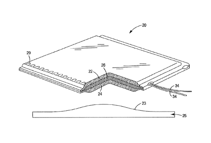
FIG. 1 illustrates a cross-sectional view of a heating blanket 20, in
accordance with an
embodiment of the present disclosure. The heating blanket 20 may comprise a
first outer layer
22, a second outer layer 24, and an interlaced heating layer 26 sandwiched
therebetween. The
first and second outer layers 22, 24 are optionally provided to protect the
interlaced heating layer
26 and to prevent users from direct contact with the interlaced heating layer
26. As will be
understood more fully below, the heating blanket 20 is capable of generating
high temperatures
of at least 500 F and, in some embodiments at least 2000 F, and therefore
each of the first outer
layer 22 and the second outer layer 24 is composed of a high temperature
fabric material, such as
fiberglass, vermiculite fiberglass, or continuous ceramic oxide wire such as
that sold by 3M
under the trademark NextelTM. The high-temperature fabric material may be
formed as a thread
that is woven, so that the first outer layer 22 and second outer layer 24
easily conform to a
contoured surface 23 of a structure 25 on which the heating blanket 20 is
placed. Furthermore,
the first outer layer 22 may be joined directly to the second outer layer 24
after the interlaced
heating layer 26 is positioned therebetween. For example, a drop stitch 29 may
be used to
connect the first outer layer 22 to the second outer layer 24. The drop stitch
29 may also be
formed of a high-temperature fabric material, such as fiberglass, veiiniculite
fiberglass, or
continuous ceramic oxide wire such as that sold by 3M under the trademark
NextelTm.
Depending on the type of high-temperature fabric material that is used, the
heating blanket 20
may have more layers than the first outer layer 22 and the second outer layer
24 surrounding the
interlaced heating layer 26. Furthermore, certain heating applications may
have specific heating
requirements and/or complex geometries, in which case the heating blanket 20
may have more
than one interlaced heating layer 26, such as multiple interlaced heating
layers stacked together.
In another embodiment, the heating blanket 20 may comprise the interlaced
heating layer(s) 26
without any surrounding layers, such as the first outer layer 22 or the second
outer layer 24.
Referring now to FIG. 2, with continued reference to FIG. 1, the interlaced
heating layer
26 is shown in accordance with an embodiment of the present disclosure. The
interlaced heating
layer 26 may comprise one or more fabric threads 28 interlaced with a heat-
generating thread 30.
As used herein, the term "thread" may refer to a single strand of material or
multiple strands of
5
CA 3047685 2019-06-21
material that are bundled together into a single cord. As will be understood
more fully below, the
materials used to form the fabric thread 28 and heat-generating thread 30 are
highly formable so
that the resulting interlaced heating layer 26 easily conforms to a contoured
surface.
The fabric thread 28 is forined of a high-temperature fabric material capable
of
withstanding elevated temperatures. As used herein, the term "elevated
temperatures" includes
temperatures of at least 500 F. In some embodiments, the elevated temperature
may be at least
1000 F. In other embodiments, the elevated temperature may be at least 2000
F. Suitable high
temperature fabric materials include fiberglass, vermiculite fiberglass, or
continuous ceramic
oxide wire such as that sold by 3M under the trademark NextelTM.
The heat-generating thread 30 includes multiple components that interact to
inductively
generate heat in response to an applied electrical current. As best shown in
FIG. 3, the heat-
generating thread 30 includes a conductor wire 32 and a susceptor wire 34. The
conductor wire
32 is configured to receive an electrical current and generate a magnetic
field in response to the
electrical current. More specifically, electric current flowing through the
conductor wire 32
generates a circular magnetic field around the conductor wire 32, with a
central axis of the
magnetic field coincident with an axis 36 of the conductor wire 32. If the
conductor wire 32 is
shaped into a cylindrical coil, the resulting magnetic field is co-axial with
an axis of the coiled
conductor wire 32.
In the illustrated embodiment, the conductor wire 32 is formed of a plurality
of conductor
wire strands 32a that are bundled together to form a Litz wire, as best shown
in FIG. 3. More
specifically, each conductor wire strand 32a may include a metal core 38 and a
coating 40. The
metal core 38 may be foinied of an electrically conductive material suitable
for high temperature
applications. Exemplary metal core materials include nickel clad copper
(suitable for
temperatures up to approximately 1000 F) and pure nickel (suitable for
temperatures up to
approximately 1500 F). The coating 40 surrounding the metal core 38 is formed
of an electrical
insulator material that is rated for high-temperature applications, such as
ceramic.
A sheath 42 may be provided that surrounds and holds the plurality of
conductor wire
strands 32a in the bundled, Litz wire configuration. The sheath 42 may be a
permanent
component, in which case it is formed of a high-temperature material such as
ceramic filament.
Alternatively, the sheath 42 may be a sacrificial component that is
subsequently removed.
Exemplary sacrificial sheath materials include a low-melting point wax or
thermoplastic film,
6
CA 3047685 2019-06-21
which may be subsequently melted or burned off during fabrication of the
interlaced heating
layer 26.
The conductor wire 32 is operatively connected to a portable or fixed power
supply 44,
either directly or via wiring 45. The power supply 44 may provide alternating
current electrical
power to the conductor wire 32 and may be connected to a conventional
electrical outlet. In
addition, the power supply 44 may operate at higher frequencies. For example,
the minimum
practical frequency may be approximately 50 kilohertz, and the maximum
practical frequency
may be approximately 500 hundred kilohertz. Other frequencies, however, may be
used.
Furthermore, the power supply 44 may be connected to a controller 46 and a
voltage sensor 48 or
other sensing device configured to indicate a voltage level provided by the
power supply 44.
Based on the indicated voltage level from the voltage sensor 48, the
controller 46 may adjust the
alternating current of the power supply 44 over a predetemiined range in order
to facilitate
application of the heating blanket 20 to various heating requirements.
Furthermore, each
conductor wire strand 32a may have a diameter sized for the electrical
frequency to be carried.
For example, the diameter of each conductor wire strand 32a may be 18-38
American Wire
Gauge (AWG).
The susceptor wire 34 is configured to inductively generate heat in response
to the
magnetic field generated by the conductor wire 32. Accordingly, the susceptor
wire 34 is formed
of a metallic material that absorbs electromagnetic energy from the conductor
wire 32 and
converts that energy into heat. Thus, the susceptor wire 34 acts as a heat
source to deliver heat
via a combination of conductive and radiant heat transfer, depending on the
distance between the
susceptor wire 34 and a workpiece to be heated.
The susceptor wire 34 is formed of a material selected to have a Curie point
that
approximates a desired maximum heating temperature of the heating blanket 20.
The Curie point
is the temperature at which a material loses its permanent magnetic
properties. When used in an
inductive heating arrangement as described herein, where the susceptor wire 34
generates heat
only as long as it is responsive to the magnetic field generated by the
conductor wire 32, the
amount of heat generated by the susceptor wire 34 will decrease as the Curie
point is
approached. For example, if the Curie point of the magnetic material for the
susceptor wire 34 is
.. 500 F, the susceptor wire 34 may generate two Watts per square inch at 450
F, may decrease
heat generation to one Watt per square inch at 475 F, and may further
decrease heat generation
to 0.5 Watts per square inch at 490 F. As such, portions of the heating
blanket 20 that are cooler
7
CA 3047685 2019-06-21
due to larger heat sinks generate more heat and portions of the heating
blanket 20 that are
warmer due to smaller heat sinks generate less heat, thereby resulting in all
portions of the
heating blanket 20 arriving at approximately a same equilibrium temperature
and reliably
providing uniform temperature over the entire heating blanket 20. Thus, the
interlaced heating
.. layer 26 may provide uniform application of heat to an area to which the
heating blanket 20 is
applied, compensating for heat sinks that draw heat away from portions of the
area that is being
heated by the blanket 20. For example, the interlaced heating layer 26 will
continue to heat
portions of the area that have not reached the Curie point, while at the same
time, ceasing to
provide heat to portions of the area that have reached the Curie point. In so
doing, the
temperature-dependent magnetic properties, such as the Curie point of the
magnetic material
used in the susceptor wire 34, may prevent over-heating or under-heating of
areas to which the
heating blanket 20 is applied.
The susceptor wire 34 may be formed of a susceptor material suitable for high
temperature applications. Exemplary high temperature susceptor materials
include iron alloys,
cobalt alloys, nickel alloys, or combinations thereof. The exact composition
of the susceptor
material may be selected based on a desired Curie point. For example, pure
nickel has a Curie
point of 669 F, pure iron has a Curie point of 1418 F, and pure cobalt has a
Curie point of
2060 F. Accordingly, the amount of nickel, iron, and cobalt (as well as other
trace elements,
such as molybdenum) used in an alloy may be adjusted to achieve a desired
Curie point. An alloy
having a higher concentration of cobalt, for example, may be selected to
provide a susceptor
material having a Curie point of approximately 2000 F. Alternatively, an
alloy having a higher
concentration of iron and other materials having a lower Curie point may be
selected to provide a
susceptor material having a Curie point of approximately 500 F. Regardless of
the exact
composition of the susceptor material, the resulting Curie point of that
susceptor material will
.. approximate a maximum heating temperature of the heating blanket 20, as
noted above.
The susceptor wire 34 may be sized to balance heating capacity with the smart
response
of the wire as it reaches the Curie point of the susceptor wire material. On
the one hand, a larger
diameter susceptor wire 34 provides more mass available to provide heat at
temperatures below
the Curie point. On the other hand, an increased diameter for the susceptor
wire 34 will delay the
smart effect achieved when the susceptor wire reaches the Curie point.
Although susceptor wire
diameter may impact the watts per square inch generated by the heating blanket
20, the Curie
point of the susceptor wire 32 will still approximate the maximum temperature
of the heating
blanket 20.
8
CA 3047685 2019-06-21
The conductor wire 32 and susceptor wire 34 may be assembled together to form
the
heat-generating thread 30 suitable for interlacing with the fabric thread 28.
For example, in the
embodiment illustrated in FIG. 3, the susceptor wire 34 may be wrapped around
the conductor
wire 32 in a spiral configuration. Winding the susceptor wire 34 around the
conductor wire 32
not only positions the susceptor wire 34 sufficiently proximate the conductor
wire 32 to
magnetically couple the wires, but also mechanically secures the conductor
wire 32 in place,
which is particularly advantageous when the conductor wire 32 is formed of a
plurality of
conductor wire strands 32a. Furthermore, arranging the susceptor wire 34
around the conductor
wire 32 permits the use of a sacrificial sheath 42, as the susceptor wire 34
will secure the
conductor wire strands 32a after the sheath 42 is burned off. Alternatively,
however, an opposite
configuration may be used, in which the conductor wire 32 is wrapped around
the susceptor wire
34. Still further, other assembly configurations of the conductor wire 32 and
the susceptor wire
34 may be used that achieve the necessary electro-magnetic coupling of the
wires while also
giving the heat-generating thread 30 an assembled shape that facilitates
interlacing with the
fabric thread 28.
The fabric thread 28 and the heat-generating thread 30 are interlaced to
provide flexibility
to the interlaced heating layer 26, thereby allowing the interlaced heating
layer 26 to conform to
the contoured surface 23. The heat-generating thread 30 may be advantageously
distributed
evenly throughout the entire interlaced heating layer 26 to provide more
uniform heating across
the heating blanket 20. Furthermore, the particular type of interlacing may be
sufficiently tight to
physically support the heat-generating thread 30. Various types of patterns
and processes may
be used to form the interlaced heating layer 26. For example, the fabric
thread 28 may form one
or more weft yarns and the heat-generating thread 30 may form a warp yarn, in
which case the
fabric thread 28 and the heat-generating thread 30 may be woven together in a
plain weave 60, as
best shown in FIG. 2. Alternatively, other weave patterns for the fabric
thread 28 and the heat-
generating thread 30 may be used, such as a twill weave 62 (FIG. 4) or a satin
weave 64 (FIG. 5),
although any type of weave pattern may be used. In another example, the fabric
thread 28 and
the heat-generating thread 30 may be knitted together in a knitted pattern 66,
as shown in FIG. 6.
However, other fabric or textile producing processes than weaving and knitting
may be used to
form the interlaced heating layer 26 as well.
An alternative embodiment of an interlaced heating layer 70 is illustrated at
FIG. 7. In
this embodiment, the interlaced heating layer 70 includes a heat-generating
thread 72 that
includes a conductor wire 74 configured as a plurality of conductor wire
circuits 76, thereby to
9
CA 3047685 2019-06-21
balance the inductance and the resistance across the entire conductor wire 74.
While the heat-
generating thread 72 may also include a susceptor wire, as discussed above,
the susceptor wire is
not shown in FIG. 7 for purposes of clarity. The plurality of conductor wire
circuits 33 are
coupled in parallel to the power supply 44. One or more fabric threads 78 may
be interlaced with
the heat-generating thread 72, thereby to foul' the interlaced heating layer
70. While the
illustrated embodiment shows five conductor wire circuits 33, a greater or
fewer number of
circuits may be used.
In another alternative embodiment illustrated at FIG. 8, an interlaced heating
layer 80
includes a conductor wire arranged in a double-back configuration, thereby to
at least partially
cancel the longer-range electromagnetic field generated by the conductor wire.
The interlaced
heating layer 80 includes a heat-generating thread 82 having a conductor wire
84. The heat-
generating thread 82 may also include a susceptor wire, but the susceptor wire
is not shown in
FIG. 8 for purposes of clarity. The conductor wire 84 includes a first segment
86 extending from
the power supply 44 to a u-bend 88, and a second segment 90 extending from the
U-bend 88
back to the power supply 44 and positioned directly adjacent the first segment
86. The first
segment 86 is carries current in a first direction, while the second segment
90 carries current in a
second direction opposite the first direction. Because the first and second
segments 86, 90 will
have the same current flowing in opposite directions, the double-back
configuration
advantageously at least partially cancels the longer-range electromagnetic
field generated by the
conductor wire 84. Additionally, the double-back configuration locates the
ends of the conductor
wire 84 adjacent each other, facilitating connection to the power supply 44
from a single end of
the interlaced heating layer 80. One or more fabric threads 92 may be
interlaced with the heat-
generating thread 82 to complete the interlaced heating layer 80.
In a further embodiment illustrated at FIG. 9, an interlaced heating layer 100
may be
formed of just a conductor wire 102 and a susceptor wire 104, omitting the
fabric thread. In this
embodiment, instead of coiling the susceptor wire 104 around the conductor
wire 102, the
susceptor wire 104 is interlaced with the conductor wire 102 to form the
interlaced heating layer
100. Any interlacing configuration may be used, including the weave and knit
patterns disclosed
herein, to interlace the conductor wire 102 and the susceptor wire 104 to form
the interlaced
heating layer 100 such that it readily conforms to a contoured surface.
Furthermore, the
conductor wire 102 and the susceptor wire 104 of the interlaced heating layer
100 are formed of
materials suitable for use in high-temperature applications, such as the
materials noted above.
CA 3047685 2019-06-21
In general, the foregoing disclosure provides numerous technical effects and
benefits in
various applications relating to high temperature heating blankets. For
example, the disclosed
heating blanket can be used to cure coatings, process and repair ceramic
material, perform
pipeline weldment repair, preheat welds, relieve stresses after welding, and
other industrial,
manufacturing, and repair applications requiring heating to at least 500 F.
The disclosed heating
blanket provides uniform, controlled heating of surface areas. More
specifically, the Curie point
of the susceptor wire in the interlaced heating layer is used to control
temperature uniformity in
the area to which the heating blanket is applied. All portions of the area
being heated may
achieve the same temperature, such as the Curie point of the susceptor wire,
thereby helping to
prevent over-heating or under-heating of certain portions of the area being
heated. Additionally,
the materials used for the fabric thread, conductor wire 32, and susceptor
wire 34 are all selected
to permit use of the heating blanket in high temperature applications.
Referring now to FIG. 10, a method 150 of forming an interlaced heating layer
26 of a
heating blanket 20 is shown, according to another embodiment of this
disclosure. The method
150 begins at block 152, where a heat-generating thread 30 is provided. As
discussed more fully
above, the heat-generating thread includes a conductor wire 32 formed of a
plurality of
conductor wire strands 32a bundled in a Litz wire configuration. The conductor
wire 32 is
configured to generate a magnetic field in response to an electrical current
applied to the
conductor wire 32. The heat-generating thread 30 further includes a susceptor
wire 34 formed of
a susceptor material configured to inductively generate heat in response to
the magnetic field of
the conductor wire 32 when a temperature of the susceptor wire 34 is below a
Curie point of the
susceptor wire 34. As discussed more fully above, the susceptor wire 34 may be
formed of a
material capable of generating high temperature heat of at least 500 F. The
method 150
continues at block 154, where the heat-generating thread 30 is interlaced with
a fabric thread 28
to form the interlaced heating layer. The method 150 may optionally include
forming first and
second outer layers 22, 24 and positioning the first and second outer layers
22, 24 on opposite
sides of the interlaced heating layer 26, thereby to protect the interlaced
heating layer 26 and
prevent a user from directly contacting the interlaced heating layer 26.
Referring now to FIG. 11, a method 200 of heating a contoured surface is
shown,
according to another embodiment of this disclosure. The method 200 begins at
block 202 by
placing on the contoured surface 25 a heating blanket 20. The heating blanket
20 has an
interlaced heating layer 26 that includes a fabric thread 28 formed of a high
temperature fabric
material, and a heat-generating thread 30 interlaced with the fabric thread
28. The heat-
11
CA 3047685 2019-06-21
generating thread 30 includes a conductor wire 32 configured to generate a
magnetic field in
response to an electrical current applied to the conductor wire 32, and a
susceptor wire 34
foiined of a susceptor material configured to inductively generate heat in
response to the
magnetic field of the conductor wire 32. The susceptor wire 34 may be formed
of a susceptor
wire material capable of generating high temperature heat of at least 500 F.
Furtheimore, the
susceptor wire material may have a Curie point at which the susceptor wire 34
reduces or ceases
heat generation, thereby providing a smart response that generates more
uniform heating
temperatures across the entire heating blanket 20. The Curie point may
approximate the
maximum temperature provided by the heating blanket 20, and therefore in some
embodiments
may be at least 500 F. At block 204, the power supply is connected to the
conductor wire 32 to
Ruin a circuit, such as via wiring 45. At block 206, a controller 46 and
voltage sensor 48 may be
operatively coupled to the power supply 44 to provide controlled power for
various heating
requirements.
It is to be understood that the flowcharts in FIGS. 10 and 11 are shown and
described as
examples only to assist in disclosing the features of the disclosed systems
and techniques, and
that more or less steps than that shown may be included in the processes
corresponding to the
various features described above for the disclosed systems without departing
from the scope of
this disclosure.
All methods described herein can be performed in any suitable order unless
otherwise
indicated herein or otherwise clearly contradicted by context. The use of any
and all examples, or
exemplary language (e.g., "such as") provided herein, is intended to
illuminate the disclosed
subject matter and does not pose a limitation on the scope of the claims. Any
statement herein as
to the nature or benefits of the exemplary embodiments is not intended to be
limiting, and the
appended claims should not be deemed to be limited by such statements. More
generally, no
language in the specification should be construed as indicating any non-
claimed element as being
essential to the practice of the claimed subject matter. Additionally, aspects
of the different
embodiments can be combined with or substituted for one another. Finally, the
description herein
of any reference or patent, even if identified as "prior," is not intended to
constitute a concession
that such reference or patent is available as prior art against the present
disclosure.
12
Date Recue/Date Received 2023-02-27