Note: Descriptions are shown in the official language in which they were submitted.
MULTIFUNCTIONAL DOWNHOLE TOOLS
BACKGROUND
[0001] Oil and natural gas wells often utilize wellbore components or tools
that, due
to their function, are only required to have limited service lives that are
considerably less than
the service life of the well. After a component or tool service function is
complete, it must be
removed or disposed of in order to recover the original size of the fluid
pathway for use,
including hydrocarbon production, CO2 sequestration, etc. Disposal of
components or tools
has conventionally been done by milling or drilling the component or tool out
of the
wellbore, which are generally time consuming and expensive operations.
[0002] Recently, self-disintegrating or interventionless downhole tools have
been
developed. Instead of milling or drilling operations, these tools can be
removed by
dissolution of engineering materials using various wellbore fluids. Because
downhole tools
are often subject to high pressures, a disintegrable material with a high
mechanical strength is
often required to ensure the integrity of the downhole tools. In addition, the
material must
have minimal disintegration initially so that the dimension and pressure
integrities of the
tools are maintained during tool service. Ideally the material can
disintegrate rapidly after the
tool function is complete because the sooner the material disintegrates, the
quicker the well
can be put on production.
[0003] One challenge for the self-disintegrating or interventionless downhole
tools is
that the disintegration process can start as soon as the conditions in the
well allow the
corrosion reaction of the engineering material to start. Thus the
disintegration period is not
controllable as it is desired by the users but rather ruled by the well
conditions and product
properties. For certain applications, the uncertainty associated with the
disintegration period
and the change of tool dimensions during disintegration can cause difficulties
in well
operations and planning. An uncontrolled disintegration can also delay well
productions.
Therefore, the development of downhole tools that have minimal or no
disintegration during
the service of the tools so that they have the mechanical properties necessary
to perform their
intended function and then rapidly disintegrate in response to a customer
command is very
desirable. It would be a further advantage if such tools can also detect real
time tool
disintegration status and well conditions such as temperature, pressure, and
tool position for
tool operations and control.
Date Recue/Date Received 2020-11-10
BRIEF DESCRIPTION
[0004] A downhole assembly comprises a disintegrable article that includes a
matrix
material; an energetic material configured to generate energy upon activation
to facilitate the
disintegration of the disintegrable article; and a sensor.
[0005] A method of controllably removing a disintegrable downhole article
comprises
disposing the downhole article in a downhole environment, the downhole article
including a
matrix material, an energetic material configured to generate energy upon
activation to
facilitate the disintegration of the downhole article, and a sensor;
performing a downhole
operation; activating the energetic material; and disintegrating the downhole
article.
[0006] A downhole assembly is characterized by a disintegrable article that
includes:
a matrix material; an energetic material configured to generate energy upon
activation to
facilitate the disintegration of the disintegrable article; and a sensor,
wherein the sensor is
configured to monitor a parameter of the disintegrable article, the downhole
assembly, a well
condition, or a combination comprising at least one of the foregoing, and the
sensor is
operative to determine a change of the parameter to trigger the activation of
the energetic
material.
[0006a] A method of controllably removing a disintegrable downhole article
comprises: disposing the downhole article in a downhole environment, the
downhole article
including a matrix material, an energetic material configured to generate
energy upon
activation to facilitate the disintegration of the downhole article, and a
sensor; performing a
downhole operation; activating the energetic material; and disintegrating the
downhole
article, wherein the sensor is configured to monitor a parameter of the
disintegrable article,
the downhole assembly, a well condition, or a combination comprising at least
one of the
foregoing, and the sensor is operative to determine a change of the parameter
to trigger the
activation of the energetic material.
2
Date Recue/Date Received 2020-11-10
BRIEF DESCRIPTION OF THE DRAWINGS
[0007] The following descriptions should not be considered limiting in any
way.
With reference to the accompanying drawings, like elements are numbered alike:
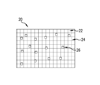
[0008] FIG. 1 is a schematic diagram of an exemplary disintegrable article
that
includes a matrix material, an energetic material, and a sensor, wherein the
energetic material
comprises interconnected fibers or wires;
[0009] FIG. 2 is a schematic diagram of an exemplary disintegrable article
that
includes a matrix material, an energetic material, and a sensor, wherein the
energetic material
is randomly distributed in the matrix material;
[0010] FIG. 3 is a schematic diagram of an exemplary disintegrable article
that
includes an inner portion and an outer portion disposed of the inner portion,
the inner portion
comprising a disintegrable material, and the outer portion comprising a matrix
material and
an energetic material;
[0011] FIG. 4 is a schematic diagram of another exemplary disintegrable
article that
includes an inner portion and an outer portion disposed of the inner portion,
wherein the outer
portion includes a layered structure;
[0012] FIG. 5 is a schematic diagram illustrating a downhole assembly disposed
in a
downhole environment according to an embodiment of the disclosure; and
[0013] FIGS. 6A-6F illustrate a process of disintegrating a downhole article
according to an embodiment of the disclosure, where FIG. 6A illustrates a
disintegrable
article before activation; FIG. 6B illustrates the disintegrable article of
FIG. 6A after
2a
Date Recue/Date Received 2020-11-10
CA 03047718 2019-06-19
WO 2018/118295 PCT/US2017/062263
activation; FIG. 6C illustrates an energetic material broken from the
activated disintegrable
article of FIG. 6B; FIG. 6D illustrates a matrix material broken from the
activated
disintegrable article of FIG. 6B; FIG. 6E illustrates a sensor material broken
from the
activated disintegrable article of FIG. 6B; and FIG. 6F illustrates a powder
generated from
the activated disintegrable article of FIG. 6B.
DETAILED DESCRIPTION
[0014] The disclosure provides multifunctional downhole articles that can
monitor
tool disintegration status, tool positions and surrounding well conditions
such as temperature,
pressure, fluid type, concentrations, and the like. Meanwhile, the downhole
articles have
minimized disintegration rate or no disintegration while the articles are in
service but can
rapidly disintegrate in response to a triggering signal or activation command
The
disintegrable articles include a matrix material; an energetic material
configured to generate
energy upon activation to facilitate the disintegration of the disintegrable
article; and a sensor.
The disintegration of the articles can be achieved through chemical reactions,
thermal
cracking, mechanical fracturing, or a combination comprising at least one of
the foregoing.
[0015] The energetic material can be in the form of continuous fibers, wires,
foils,
particles, pellets, short fibers, or a combination comprising at least one of
the foregoing. In
the disintegrable articles, the energetic material is interconnected in such a
way that once a
reaction of the energetic material is initiated at one or more starting
locations or points, the
reaction can self-propagate through the energetic material in the
disintegrable articles. As
used herein, interconnected or interconnection is not limited to physical
interconnection.
[0016] In an embodiment the energetic material comprises continuous fibers,
wires,
or foils, or a combination comprising at least one of the foregoing and forms
a three
dimensional network. The matrix material is distributed throughout the three
dimensional
network. A disintegrable article having such a structure can be formed by
forming a porous
preform from the energetic material, and filling or infiltrating the matrix
material into the
preform under pressure at an elevated temperature. The sensor can be placed at
a random or
a pre-determined location in the disintegrable article.
[0017] In another embodiment, the energetic material is randomly distributed
in the
matrix material in the form of particles, pellets, short fibers, or a
combination comprising at
least one of the foregoing. A disintegrable article having such a structure
can be formed by
mixing and compressing the energetic material and the matrix material. The
sensor can be
placed at a random or a pre-determined location in the disintegrable article.
3
CA 03047718 2019-06-19
WO 2018/118295 PCT/US2017/062263
[0018] In yet another embodiment, the disintegrable article comprises an inner
portion and an outer portion disposed of the inner portion, where the inner
portion comprises
a core material that is corrodible in a downhole fluid; and the outer portion
comprises the
matrix material and the energetic material. The sensor can be disposed in the
inner portion of
the disintegrable article, the outer portion of the disintegrable article, or
both. Illustrative
core materials include corrodible matrix materials disclosed herein. The inner
portion can
include a core matrix formed from the core materials. Such a core matrix can
have a
microstructure as described herein for the corrodible matrix.
[0019] When the inner portion is surrounded and encased by the outer portion,
the
core material in the inner portion of the article and matrix material in the
outer portion of the
article are selected such that the core material has a higher corrosion rate
than the matrix
material when tested under the same conditions.
[0020] The outer portion of the articles can comprise a network formed by an
energetic material in the form of continuous fibers, wires, or foils, or a
combination
comprising at least one of the foregoing, and a matrix material distributed
throughout the
network of the energetic material. The outer portion of the disintegrable
articles can also
contain an energetic material randomly distributed in a matrix material in the
form of
particles, pellets, short fibers, or a combination comprising at least one of
the foregoing. In
an embodiment, the outer portion has a layered structure including matrix
layers and
energetic material layers. An exemplary layered structure has alternating
layers of a matrix
material and an energetic material. The arrangement allows for selective
removal of a
portion of the disintegrable article upon selective activation of one or more
layers of the
energetic material.
[0021] Once the energetic material in the outer portion of the article is
activated, the
outer portion disintegrates exposing the inner portion of the article. Since
the inner portion of
the article has an aggressive corrosion rate in a downhole fluid, the inner
portion of the article
can rapidly disintegrate once exposed to a downhole fluid.
[0022] The matrix material comprises a polymer, a metal, a composite, or a
combination comprising at least one of the foregoing, which provides the
general material
properties such as strength, ductility, hardness, density for tool functions.
As used herein, a
metal includes metal alloys. The matrix material can be corrodible or non-
corrodible in a
downhole fluid. The downhole fluid comprises water, brine, acid, or a
combination
comprising at least one of the foregoing. In an embodiment, the downhole fluid
includes
potassium chloride (KC1), hydrochloric acid (HC1), calcium chloride (CaCl2),
calcium
4
CA 03047718 2019-06-19
WO 2018/118295 PCT/US2017/062263
bromide (CaBr2) or zinc bromide (ZnBr2), or a combination comprising at least
one of the
foregoing. The disintegration of the articles can be achieved through chemical
reactions,
thermal cracking, mechanical fracturing, or a combination comprising at least
one of the
foregoing. When the matrix material is not corrodible, the downhole article
can be
disintegrated by physical forces generated by the energetic material upon
activation. When
the matrix material is corrodible, the downhole article can be disintegrated
by chemical
means via the corrosion of the matrix material in a downhole fluid. The heat
generated by the
energetic material can also accelerate the corrosion of the matrix material.
Both chemical
means and physical means can be used to disintegrate downhole articles that
have corrodible
matrix materials.
[0023] In an embodiment, the corrodible matrix material comprises Zn, Mg, Al,
Mn,
an alloy thereof, or a combination comprising at least one of the foregoing.
The corrodible
matrix material can further comprise Ni, W, Mo, Cu, Fe, Cr, Co, an alloy
thereof, or a
combination comprising at least one of the foregoing.
[0024] Magnesium alloy is specifically mentioned. Magnesium alloys suitable
for
use include alloys of magnesium with aluminum (Al), cadmium (Cd), calcium
(Ca), cobalt
(Co), copper (Cu), iron (Fe), manganese (Mn), nickel (Ni), silicon (Si),
silver (Ag), strontium
(Sr), thorium (Th), tungsten (W), zinc (Zn), zirconium (Zr), or a combination
comprising at
least one of these elements. Particularly useful alloys include magnesium
alloy particles
including those prepared from magnesium alloyed with Ni, W, Co, Cu, Fe, or
other metals.
Alloying or trace elements can be included in varying amounts to adjust the
corrosion rate of
the magnesium. For example, four of these elements (cadmium, calcium, silver,
and zinc)
have to mild-to-moderate accelerating effects on corrosion rates, whereas four
others (copper,
cobalt, iron, and nickel) have a still greater effect on corrosion. Exemplary
commercial
magnesium alloys which include different combinations of the above alloying
elements to
achieve different degrees of corrosion resistance include but are not limited
to, for example,
those alloyed with aluminum, strontium, and manganese such as AJ62, AJ50x,
AJ51x, and
AJ52x alloys, and those alloyed with aluminum, zinc, and manganese such as
AZ91A-E
alloys.
[0025] It will be understood that corrodible matrix materials will have any
corrosion
rate necessary to achieve the desired performance of the disintegrable article
once the article
completes its function. In a specific embodiment, the corrodible matrix
material has a
corrosion rate of about 0.1 to about 450 mg/cm2/hour, specifically about 1 to
about 450
mg/cm2/hour determined in aqueous 3 wt.% KCl solution at 200 F (93 C).
CA 03047718 2019-06-19
WO 2018/118295 PCT/US2017/062263
[0026] In an embodiment, the matrix formed from the matrix material (also
referred
to as corrodible matrix) has a substantially-continuous, cellular nanomatrix
comprising a
nanomatrix material; a plurality of dispersed particles comprising a particle
core material that
comprises Mg, Al, Zn or Mn, or a combination thereof, dispersed in the
cellular nanomatrix;
and a solid-state bond layer extending throughout the cellular nanomatrix
between the
dispersed particles. The matrix comprises deformed powder particles formed by
compacting
powder particles comprising a particle core and at least one coating layer,
the coating layers
joined by solid-state bonding to form the substantially-continuous, cellular
nanomatrix and
leave the particle cores as the dispersed particles. The dispersed particles
have an average
particle size of about 5 pm to about 300 [tin. The nanomatrix material
comprises Al, Zn, Mn,
Mg, Mo, W, Cu, Fe, Si, Ca, Co, Ta, Re or Ni, or an oxide, carbide or nitride
thereof, or a
combination of any of the aforementioned materials. The chemical composition
of the
nanomatrix material is different than the chemical composition of the
nanomatrix material
[0027] The matrix can be formed from coated particles such as powders of Zn,
Mg,
Al, Mn, an alloy thereof, or a combination comprising at least one of the
foregoing. The
powder generally has a particle size of from about 50 to about 150
micrometers, and more
specifically about 5 to about 300 micrometers, or about 60 to about 140
micrometers. The
powder can be coated using a method such as chemical vapor deposition,
anodization or the
like, or admixed by physical method such cryo-milling, ball milling, or the
like, with a metal
or metal oxide such as Al, Ni, W, Co, Cu, Fe, oxides of one of these metals,
or the like. The
coating layer can have a thickness of about 25 nm to about 2,500 nm. Al/Ni and
Al/W are
specific examples for the coating layers. More than one coating layer may be
present.
Additional coating layers can include Al, Zn, Mg, Mo, W. Cu, Fe, Si, Ca, Co,
Ta, Re, or No.
Such coated magnesium powders are referred to herein as controlled
electrolytic materials
(CEM). The CEM materials are then molded or compressed forming the matrix by,
for
example, cold compression using an isostatic press at about 40 to about 80 ksi
(about 275 to
about 550 MPa), followed by forging or sintering and machining, to provide a
desired shape
and dimensions of the disintegrable article. The CEM materials including the
composites
formed therefrom have been described in U.S. patent Nos. 8,528,633 and
9,101,978.
[0028] The matrix material can be degradable polymers and their composites
including poly(lactic acid) (PLA), poly(glycolic acid) (PGA), polycaprolactone
(PCL),
polylactide-co-glycolide, polyurethane such as polyurethane having ester or
ether linkages,
polyvinyl acetate, polyesters, and the like.
6
CA 03047718 2019-06-19
WO 2018/118295 PCT/US2017/062263
[0029] Optionally, the matrix material fitrther comprises additives such as
carbides,
nitrides, oxides, precipitates, dispersoids, glasses, carbons, or the like in
order to control the
mechanical strength and density of the disintegrable article.
[0030] The energetic material comprises a thermite, a reactive multi-layer
foil, an
energetic polymer, or a combination comprising at least one of the foregoing.
Use of
energetic materials disclosed herein is advantageous as these energetic
materials are stable at
wellbore temperatures but produce an extremely intense exothermic reaction
following
activation, which facilitates the rapid disintegration of the disintegrable
articles.
[0031] Thermite compositions include, for example, a metal powder (a reducing
agent) and a metal oxide (an oxidizing agent) that produces an exothermic
oxidation-
reduction reaction known as a thermite reaction. Choices for a reducing agent
include
aluminum, magnesium, calcium, titanium, zinc, silicon, boron, and combinations
including at
least one of the foregoing, for example, while choices for an oxidizing agent
include boron
oxide, silicon oxide, chromium oxide, manganese oxide, iron oxide, copper
oxide, lead oxide,
and combinations including at least one of the foregoing, for example.
[0032] As used herein, energetic polymers are materials possessing reactive
groups,
which are capable of absorbing and dissipating energy. During the activation
of energetic
polymers, energy absorbed by the energetic polymers cause the reactive groups
on the
energetic polymers, such as azido and nitro groups, to decompose releasing gas
along with
the dissipation of absorbed energy and/or the dissipation of the energy
generated by the
decomposition of the active groups. The heat and gas released promote the
disintegration of
the disintegrable articles.
[0033] Energetic polymers include polymers with azide, nitro, nitrate,
nitroso,
nitramine, oxetane, triazole, and tetrazole containing groups. Polymers or co-
polymers
containing other energetic nitrogen containing groups can also be used.
Optionally, the
energetic polymers further include fluoro groups such as fluoroalkyl groups.
[0034] Exemplary energetic polymers include nitrocellulose, azidocellulose,
polysulfide, polyurethane, a fluoropolymer combined with nano particles of
combusting
metal fuels, polybutadiene; polyglycidyl nitrate such as polyGLYN, butanetriol
trinitrate,
glycidyl azide polymer (GAP), for example, linear or branched GAP, GAP diol,
or GAP triol,
poly[3-nitratomethy1-3-methyl oxetane](polyNIMMO), poly(3,3-bis-
(azidomethyl)oxetane
(polyBAMO) and poly(3-azidomethy1-3-methyl oxetane) (polyAMMO),
polyvinylnitrate,
polynitrophenylene, nitramine polyethers, or a combination comprising at least
one of the
foregoing.
7
CA 03047718 2019-06-19
WO 2018/118295 PCT/US2017/062263
[0035] The reactive multi-layer foil comprises aluminum layers and nickel
layers or
the reactive multi-layer foil comprises titanium layers and boron carbide
layers. In specific
embodiments, the reactive multi-layer foil includes alternating aluminum and
nickel layers.
[0036] The amount of the energetic material is not particularly limited and is
generally in an amount sufficient to generate enough energy to facilitate the
rapid
disintegration of the downhole articles once the energetic material is
activated. In one
embodiment, the energetic material is present in an amount of about 0.5 wt.%
to about 45
wt.% or about 0.5 wt.% to about 20 wt.% based on the total weight of the
disintegrable
articles.
[0037] The disintegrable articles also include a sensor, which is operative to
receive
and process a signal to activate an energetic material, to determine a
parameter change to
trigger the activation of an energetic material, or to monitor a parameter of
the disintegrable
article, a downhole assembly comprising the disintegrable article, a well
condition, or a
combination comprising at least one of the foregoing. The parameter includes
the
disintegration status of the downhole article, the position of the downhole
article, the position
of the downhole assembly, pressure or temperature of the downhole environment,
downhole
fluid type, flow rate of produced water, or a combination comprising at least
one of the
foregoing. The sensor comprises a sensor material, a sensor element, or a
combination
comprising at least one of the foregoing. A disintegrable article can include
more than one
sensors, where each sensor can have the same or different functions.
[0038] To receive and process a signal to activate an energetic material, the
sensor
can include a receiver to receive a disintegration signal, and a triggering
component that is
effective to generate an electric current. Illustrative triggering component
includes batteries
or other electronic components. Once a disintegration signal is received, the
triggering
component generates an electric current and triggers the activation of the
energetic material.
The disintegration signal can be obtained from the surface of a wellbore or
from a signal
source in the well, for example, from a signal source in the well close to the
disintegrable
article.
[0039] In some embodiments, no external signal source is needed. The sensor
can
detect a parameter of interest such as a pressure, stress, or mechanical force
applied to the
disintegrable. Once the detected value exceeds a predetermined threshold
value, the sensor
generates an electrical signal which triggers the activation of the energetic
material.
Illustratively, a piezoelectric material can be used as the sensor material.
The piezoelectric
material detects a pressure such as hydraulic pressure, stress, or mechanical
force applied to
8
CA 03047718 2019-06-19
WO 2018/118295 PCT/US2017/062263
the downhole article. In the event that the detected pressure, stress, or
mechanical force is
greater than a predetellnined value, the piezoelectric material generates an
electrical charge to
activate the energetic material.
[0040] The disintegrable sensor can also be configured to determine the
disintegration
status of the downhole article. For example, sensors with different tracer
materials can be
placed at different locations of the downhole article. The disintegration of
the downhole
article releases the tracer materials. Depending on the type of tracer
materials detected, real
time disintegration status can be determined. Alternatively or in addition, in
the event that
the matrix material releases a detectable chemical upon corrosion, the
detectable chemical
can also be used to provide disintegration information of the downhole
article.
[0041] In some embodiments, the sensor includes chemical sensors configured
for
elemental analysis of conditions (e.g., fluids) within the wellbore. For
example, the sensor
can include carbon nanotubes (CNT), complementary metal oxide semiconductor
(CMOS)
sensors configured to detect the presence of various trace elements based on
the principle of a
selectively gated field effect transistors (FET) or ion sensitive field effect
transistors (ISFET)
for pH, H2S and other ions, sensors configured for hydrocarbon analysis, CNT,
DLC based
sensors that operate with chemical electropotential, and sensors configured
for carbon/oxygen
analysis. Some embodiments of the sensor may include a small source of a
radioactive
material and at least one of a gamma ray sensor or a neutron sensor.
[0042] The sensor can include other sensors such as pressure sensors,
temperature
sensors, stress sensors and/or strain sensors. For example, pressure sensors
may include
quartz crystals. Piezoelectric materials may be used for pressure sensors.
Temperature
sensors may include electrodes configured to perform resistivity and
capacitive
measurements that may be converted to other useful data. Temperature sensors
can also
comprise a thermistor sensor including a thermistor material that changes
resistivity in
response to a change in temperature.
[0043] In some embodiments, the sensor includes a tracer material such as an
inorganic cation; an inorganic anion; an isotope; an activatable element; or
an organic
compound. Exemplary tracers include those described in US 20160209391. The
tracer
material can be released from the disintegrable articles while the articles
disintegrate. The
concentration of the release tracer material can be measured thus providing
information such
as concentration of water or flow rate of produced water.
9
CA 03047718 2019-06-19
WO 2018/118295
PCT/US2017/062263
[0044] The sensor may couple with a data processing unit. Such data processing
unit
includes electronics for obtaining and processing data of interest. The data
processing unit
can be located downhole or on the surface.
[0045] The microstructures of the exemplary disintegrable articles according
to
various embodiments of the disclosure are illustrated in FIGS. 1-4. Referring
to FIG. 1, the
disintegrable article 20 includes matrix 22, energetic material 24, and
sensors 26. The
energetic material forms an interconnected network. The sensors are randomly
or purposely
positioned in the disintegrable article.
[0046] The disintegrable article 30 illustrated in FIG. 2 includes matrix 32,
energetic
material 34, and sensors 36, where the energetic material 34 is randomly
dispersed within
matrix 32 as particles, pellets, short fibers, or a combination comprising at
least one of the
foregoing.
[0047] The disintegrable article 40 illustrated in FIG. 3 includes an inner
portion 45
and an outer portion 42, wherein the inner portion 45 contains a core material
41 and the
outer portion 42 contains an energetic material 44 and matrix 43. Sensors 46
can be
positioned in the inner portion 45, in the outer portion 42, or both. Although
in FIG. 3, it is
shown that the energetic material 44 is randomly distributed in the matrix 43
in the outer
portion 42 of the disintegrable article 40, it is appreciated that the outer
portion 42 can also
have a structure as shown in FIG. 1 for article 20.
[0048] The disintegrable article 50 illustrated in FIG. 4 includes an inner
portion 55
and an outer portion 52, wherein the inner portion 55 contains a core material
51 and the
outer portion 52 has a layered structure that contains matrix layers 53 and
energetic material
layers 54. Sensors (not shown) can be disposed in the inner portion, the outer
portion, or
both.
[0049] Disintegrable articles in the downhole assembly are not particularly
limited.
Exemplary articles include a ball, a ball seat, a fracture plug, a bridge
plug, a wiper plug,
shear out plugs, a debris barrier, an atmospheric chamber disc, a swabbing
element protector,
a sealbore protector, a screen protector, a beaded screen protector, a screen
basepipe plug, a
drill in stim liner plug, ICD plugs, a flapper valve, a gaslift valve, a
transmatic CEM plug,
float shoes, darts, diverter balls, shifting/setting balls, ball seats,
sleeves, teleperf disks, direct
connect disks, drill-in liner disks, fluid loss control flappers, shear pins
or screws, cementing
plugs, teleperf plugs, drill in sand control beaded screen plugs, HP beaded
frac screen plugs,
hold down dogs and springs, a seal bore protector, a stimcoat screen
protector, or a liner port
plug. In specific embodiments, the disintegrable article is a ball, a fracture
plug, a
CA 03047718 2019-06-19
WO 2018/118295 PCT/US2017/062263
whipstock, a cylinder, or a liner plug. A downhole assembly comprising the
disintegrable
article is also provided.
[0050] The disintegrable articles disclosed herein can be controllably removed
such
that significant disintegration only occurs after these articles have
completed their functions.
A method of controllably removing a disintegrable article comprises disposing
a disintegrable
article comprising a matrix material, an energetic material, and a sensor in a
downhole
environment; performing a downhole operation; activating the energetic
material; and
disintegrating the downhole article.
[0051] The method further comprises determining a parameter of the downhole
article, a downhole assembly comprising the downhole article, the downhole
environment, or
a combination comprising at least one of the foregoing. The parameter
comprises
disintegration status of the downhole article, the position of the downhole
article, position of
the downhole assembly, pressure or temperature of the downhole environment,
flow rate of
produced water, or a combination comprising at least one of the foregoing.
[0052] The methods allow for a full control of the disintegration profile. The
disintegrable articles can retain their physical properties until a signal or
activation command
is produced. Because the start of the disintegration process can be
controlled, the
disintegrable articles can be designed with an aggressive corrosion rate in
order to accelerate
the disintegration process once the articles are no longer needed.
[0053] The disintegrable article or a downhole assembly comprising the same
can
perform various downhole operations while the disintegration of the article is
minimized.
The downhole operation is not particularly limited and can be any operation
that is performed
during drilling, stimulation, completion, production, or remediation.
[0054] Once the disintegrable article is no longer needed, the disintegration
of the
article is activated. The method can further comprise receiving an instruction
or signal from
above the ground or generating an instruction or signal downhole to activate
the energetic
material. Activating the energetic material comprises providing a command
signal to the
downhole article, the command signal comprising electric current,
electromagnetic radiation
such as microwaves, laser beam, mud pulse, hydraulic pressure, mechanical
fore, or a
combination comprising at least one of the foregoing. The command signal can
be provided
above the surface or generated downhole. In an embodiment, activating the
energetic
material comprises detecting a pressure, stress, or mechanical force applied
to the
disintegrable article to generate a detected value; comparing the detected
value with a
threshold value; and generating an electrical change to activate the energetic
material when
11
the detected value exceeds the threshold value. In another embodiment,
activating the
energetic material incudes receiving a command signal by the sensor, and
generating an
electric current by the sensor to activate the energetic material. Activating
the energetic
material can further comprise initiating a reaction of the energetic material
to generate heat.
[0055] Referring to FIG. 5, a downhole assembly 16 is disposed in wellbore 17
via a
coil tubing or wireline 12. A communication line 10 couples the downhole
assembly to a
processor 15. The communication line 10 can provide a command signal such as a
selected
form of energy from processor 15 to the downhole assembly to activate the
energetic material
in the downhole assembly. The communication line 10 can also process the data
generated
by the sensor in the disintegrable article to monitor the disintegration
status of the downhole
assembly, position of the downhole assembly and the well conditions. The
communication
line 10 can be optical fibers, electric cables or the like, and it can be
placed inside of the coil
tubing or wireline 12.
[0056] Referring to FIGS. 6A-6E, before activation, a disintegrable article as
shown
in FIG. 6A contains an energetic material network, a matrix, and sensors.
After activation,
heat is generated, and the disintegration article as shown in FIG. 6B breaks
into small pieces,
such as an energetic material, a matrix material, and a sensor material as
shown in FIGS. 6C,
6D, and 6E respectively. In an embodiment, the small pieces can further
corrode in a
downhole fluid forming powder particles as shown in FIG. 6F. The powder
particles can
flow back to the surface thus conveniently removed from the wellbore.
[0057] All ranges disclosed herein are inclusive of the endpoints, and the
endpoints
are independently combinable with each other. As used herein, -combination" is
inclusive of
blends, mixtures, alloys, reaction products, and the like.
[0058] The use of the terms -a" and -an" and "the" and similar referents in
the
context of describing the invention (especially in the context of the
following claims) are to
be construed to cover both the singular and the plural, unless otherwise
indicated herein or
clearly contradicted by context. -Or" means -and/or." The modifier -about"
used in
connection with a quantity is inclusive of the stated value and has the
meaning dictated by the
context (e.g., it includes the degree of error associated with measurement of
the particular
quantity).
12
Date Recue/Date Received 2020-11-10