Note: Descriptions are shown in the official language in which they were submitted.
CA 03047839 2019-06-20
WO 2018/112635
PCT/CA2017/051558
APPARATUS FOR STORING AIRPLANES
TECHNICAL FIELD
[0001] The present invention relates to apparatuses for storing airplanes.
BACKGROUND OF THE INVENTION
[0002] Airplanes are stored in hangars to secure them and protect them from
damaging
environmental elements such as ultraviolet radiation and extreme temperatures.
However,
construction costs, operating costs, land scarcity, and other practical
considerations limit
the size of hangars. Accordingly, economical use of hangars requires airplanes
to be
stored in a space efficient manner.
[0003] In order to conserve space within hangars, airplanes may be parked so
that the
wings of different airplanes horizontally interleave or vertically overlap
each other.
However, positioning airplanes in such close proximity is inconvenient and
difficult for a
single person, and raises the risk of "hangar rash" ¨ i.e., damage to the
airplanes due to
contact between the airplanes during ground handling.
[0004] The prior art includes apparatuses for storing airplanes that include
elevators for
moving airplanes between ground level and elevated rotatable platforms.
Examples of
such apparatuses are disclosed in U.S. Patent No. 3,599,809 (Gresham), U.S.
Patent No.
3,670,464 (Cutter), U.S. Patent No. 3,675,378 (Neumann et al.), U.S. Patent
No.
3,915,319 (Fairburn), and International Patent Application Publication WO
2013/057706
(Schaetz). It will be appreciated that in the use of such apparatuses, the
airplanes must
first be moved from the elevated platform onto the elevators before being
lowered to
ground level. Further, since the elevators must be large enough to support an
airplane,
such apparatuses make suboptimal use of hangar space if the elevators are
placed inside
the hangars.
[0005] U.S. Patent No. 4,697,392 (Silzle) discloses an apparatus having a
lower platform
for supporting airplanes and raised lifting platforms for supporting
additional airplanes in
a nested configuration with the airplanes on the lower platform. The lifting
platforms
radiate from the central axis and rotate in unison with the lower platform
about the
central axis. A hydraulic piston moves the lifting platforms on pivoting
levers so that the
1
CA 03047839 2019-06-20
WO 2018/112635
PCT/CA2017/051558
lifting platforms move simultaneously downwardly and radially outward from the
central
axis beyond the periphery of a lower platform so as to project through an open
door of
the hangar. It will be appreciated that use of the hangar space is suboptimal
if the lifting
platforms are to remain inside the hangar at all times, since the lifting
platforms extend
beyond the periphery of the lower platform when lowered.
[0006] Additional examples of apparatuses for ground handling and/or storing
airplanes
are disclosed in U.S. Patent No. 3,954,197 (Dean), U.S. Patent No. 5,141,371
(Pish), U.S.
Patent No. 6,155,003 (Smith), U.S. Patent No. 6,672,221 (Hadley), U.S. Patent
No.
7,465,141 (Fournier et al.), U.S. Patent Application Publication 2006/0038069
(Cawley),
U.K. Patent Application Publication GB 2,376,005 (Haig), International Patent
Application Publication WO 96/13428 (Leonard), and German Patent Application
Publication DE 3545888 Al (Schaetz).
SUMMARY OF THE INVENTION
[0007] An objective of the present invention is to provide an apparatus
suitable for use
inside hangars that allows for space-efficient storage of airplanes. Another
objective of
the present invention is to provide an apparatus for storing airplanes that
allows for
convenient movement of airplanes between airplane parking floors at different
elevations,
and positions for ingress and egress from a hangar, by a single operator and
with limited
towing or moving of airplanes. Another objective of the present application is
to provide
an apparatus for storing airplanes that selectively restricts access to
airplanes to
authorized operators. Other objectives of the present invention may include
providing an
apparatus that reduces the risk of contact between airplanes in hangars, and
helps to
control the temperature inside hangars when airplanes enter and exit through
hangar door
openings. It will be understood, however, that the foregoing aspirations of
the present
invention are not promised advantages of any particular embodiment of the
present
invention.
[0008] In one aspect, the present invention comprises an apparatus for storing
airplanes.
The apparatus comprises a first airplane parking floor at a first elevation,
and a second
2
CA 03047839 2019-06-20
WO 2018/112635
PCT/CA2017/051558
airplane parking floor at a second elevation different from the first
elevation, and an
elevator.
[0009] The first airplane parking floor is shaped to define a vacant region at
the first
elevation in which the first airplane parking floor is absent. The vacant
region is
positioned within a notional circle circumscribing the first airplane parking
floor at the
first elevation and defining a notional circumcenter.
[0010] The second airplane parking floor comprises a plurality of separable
second
airplane parking floor regions, each of which is proportioned for parking one
of the
airplanes thereon. The second airplane parking floor is rotatable about the
circumcenter
for selective angular alignment of an individual one of the second airplane
parking floor
regions with the vacant region.
[0011] The elevator vertically translates the individual one of the second
airplane parking
floor regions, when in angular alignment with the vacant region, between the
second
elevation and the vacant region at the first elevation.
[0012] In embodiments of the apparatus, the first airplane parking floor
comprises a
plurality of first airplane parking floor regions, each of which is
proportioned for parking
one of the airplanes thereon. In embodiments, the first airplane parking floor
regions may
be separable from each other.
[0013] In embodiments of the apparatus, the first airplane parking floor is
rotatable about
the circumcenter, for selective angular alignment of an individual one of the
first airplane
parking floor regions or the vacant region within a fixed sector of the
notional circle.
[0014] In embodiments of the apparatus, the apparatus may further comprise at
least one
pair of first walls attached to and extending upwardly from the first airplane
parking floor
for separating one of the first airplane parking floor regions from an
adjacent one or
adjacent ones of the first airplane parking floor regions.
[0015] In embodiments of the apparatus, the apparatus may further comprise a
first
access wall extending along an outer edge of one of the first airplane parking
floor
3
CA 03047839 2019-06-20
WO 2018/112635
PCT/CA2017/051558
regions. The first airplane parking floor may rotate relative to the first
access wall when
the first airplane parking floor rotates about the circumcenter. The first
access wall may
define an opening for a human to move into and out of the one of the first
airplane
parking floor regions.
[0016] In embodiments of the apparatus, the apparatus further comprises at
least one pair
of second walls attached to and extending upwardly from the second airplane
parking
floor for separating one of the second airplane parking floor regions from an
adjacent one
or adjacent ones of the second airplane parking floor regions.
[0017] In embodiments of the apparatus, the apparatus further comprises an
access floor
at the second elevation, adjacent to at least a portion of the edge of the
second airplane
parking floor, and extending radially away from the circumcenter.
[0018] In embodiments of the apparatus, the apparatus further comprises a
second access
wall extending along an outer edge of one of the second airplane parking floor
regions.
The second airplane parking floor may rotate relative to the second access
wall when the
second airplane parking floor rotates about the circumcenter. The second
access wall may
define an opening for a human to move into and out of the one of the second
airplane
parking floor regions.
[0019] In embodiments of the apparatus, the elevator is positioned to
selectively engage
the individual one of the second airplane parking floor regions in angular
alignment with
the vacant region, without engaging the other one or ones of the second
airplane parking
floor regions that are not in angular alignment with the vacant region.
BRIEF DESCRIPTION OF DRAWINGS
[0020] In the drawings, like elements are assigned like reference numerals.
The drawings
are not necessarily to scale, with the emphasis instead placed upon the
principles of the
present invention. Additionally, each of the embodiments depicted is but one
of a
number of possible arrangements utilizing the fundamental concepts of the
present
invention. The drawings are briefly described as follows:
4
CA 03047839 2019-06-20
WO 2018/112635
PCT/CA2017/051558
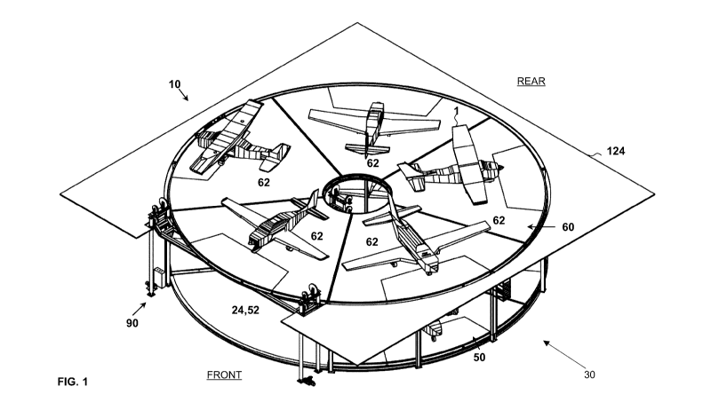
[0021] Fig. 1 is a perspective view of one embodiment of an apparatus of the
present
invention for storing airplanes, shown with parked airplanes;
[0022] Fig. 2 is a top plan view of a first airplane parking floor of the
apparatus shown in
Fig. 1;
[0023] Fig. 3 is a perspective view of the structure and elevator of the
apparatus shown in
Fig. 1;
[0024] Fig. 4 is a front elevation view of the structure and elevator shown in
Fig. 3;
[0025] Fig. 5 is a top plan view of the structure shown in Fig. 3 as viewed
along line E-E
of Fig. 4;
[0026] Fig. 6 is a top plan view of the structure shown in Fig. 3 as viewed
along line F-F
of Fig. 4;
[0027] Fig. 7 is a front elevation view of the apparatus shown in Fig. 1;
[0028] Fig. 8 is a top plan view of the apparatus shown in Fig. 1 as viewed
along line A-
A of Fig. 7;
[0029] Fig. 9 is a top plan view of the apparatus shown in Fig. 1 as viewed
along line B-
B of Fig. 7;
[0030] Fig. 10 is a perspective view of an embodiment of an airplane parking
floor panel
upper layer of the apparatus shown in Fig. 1;
[0031] Fig. 11 is a bottom plan view of an embodiment of an airplane parking
floor
panels of the apparatus shown in Fig. 1;
[0032] Fig. 12 is a detailed view of region A of Fig. 3, showing a second
motor for
rotating the second airplane parking floor;
[0033] Fig. 13 is a perspective view of the elevator shown in Fig. 3;
[0034] Fig. 14 is a perspective view of the apparatus shown in Fig. 1, with
first walls,
second walls and access walls;
CA 03047839 2019-06-20
WO 2018/112635
PCT/CA2017/051558
[0035] Fig. 15 is a perspective view of the apparatus shown in Fig. 14, inside
a hangar;
and
[0036] Figs.16A to 16H are successive perspective views showing an exemplary
use and
operation of the apparatus shown in Fig. 14.
DETAILED DESCRIPTION OF THE INVENTION
[0037] The present invention relates to an apparatus for storing airplanes.
Any term or
expression not expressly defined herein shall have its commonly accepted
definition
understood by a person skilled in the art.
[0038] Apparatus in general. In an exemplary embodiment as shown in Figure 1,
the
apparatus (10) comprises a structure (30) (shown more clearly in Figure 3), a
first
airplane parking floor (50) at a first elevation, a second airplane parking
floor (60) at a
second elevation different than the first elevation, and an elevator (90).
[0039] In the exemplary embodiment shown in Figure 1, the first elevation is
substantially at ground level, and the second elevation is above ground level.
For
example, the first elevation may be substantially level with the top surface
of an apron in
front of a hangar door, with the structure underlying the first airplane
parking floor (30)
recessed below the top surface of the apron. In other embodiments (not shown)
the first
elevation may be above or below ground level, and the second elevation may be
below
the first elevation.
[0040] In the following description, and as shown in Figure 2, the
relationship between
the structure (30), the first airplane parking floor (50), the second airplane
parking floor
(60), and the elevator (90) are described with reference to a notional circle
(20) that
circumscribes the first airplane parking floor (50) at the first elevation,
defines a notional
circumcenter (22), and defines a fixed sector (24). As used herein, the term
"circumscribes" means that the notional circle (20) is the smallest
horizontally oriented
circle at the first elevation that completely contains the first airplane
parking floor (50).
As used herein, the term "circumcenter" refers to the center of such a
circumscribed
notional circle (20). As used herein, the term "sector" refers to a region of
such a
6
CA 03047839 2019-06-20
WO 2018/112635
PCT/CA2017/051558
circumscribed notional circle (20) that is bound by two radii of the notional
circle (20).
As used herein, the term "central angle", in relation to the fixed sector
(24), is the angle
having the notional circumcenter (22) as the apex and defined between the two
bounding
radii of the fixed sector (24). As used herein, the term "angular alignment"
in describing
the spatial relationship between two components of the apparatus (10) means
that both
components may be intersected by a vertically extending plane projected
radially from
the notional circumcenter (22).
[0041] In the exemplary embodiment of the first airplane parking floor (50)
shown in
Figure 2, the notional circle (20) is shown with a dashed line and its
notional
circumcenter (22) is shown as a point, and its fixed sector (24) is shown as
towards the
bottom of Figure 2. For clarity of Figure 2, the notional circle (20) is shown
as slightly
separated from the outer edge of the first airplane parking floor (50), but it
will be
understood that the notional circle (20) is touching portions of the outer
edge of the first
airplane parking floor (50).
[0042] In the exemplary embodiment shown in Figure 1, the apparatus (10) is
used to
store at total of nine fixed wing airplanes (four on the first airplane
parking floor (50),
and five on the second airplane parking floor (60)), each of the airplanes
having a
wingspans of approximately 10 meters (33 feet), such as a Cirrus TM model
SR22, Cessna
TM TM
models 185 (on amphibious floats), 340, 421, or a Piper Meridian . It
will be
understood that these examples are non-limiting of the present invention.
Accordingly, in
the exemplary use, the apparatus (10) is scaled such that the notional circle
(20) has a
diameter of approximately 30 meters (100 feet). Further, the central angle of
the fixed
sector (24) is selected to be approximately 72 degrees so that the chord
extending
between the end points of the arc defined by the fixed sector (24) spans
approximately 18
meters (60 feet). Further, in the exemplary embodiment in Figure 1, opposite
end of the
apparatus (10) have been labelled as "FRONT" and "REAR" for convenient
reference. In
exemplary use, as shown in Figure 15, the apparatus (10) may be installed
inside a
hangar, with the portion of the apparatus (10) most proximal to "FRONT" being
placed
adjacent to a hangar door (e.g., a bi-fold type door or other types of doors)
for ingress and
7
CA 03047839 2019-06-20
WO 2018/112635
PCT/CA2017/051558
egress of airplanes from the hangar. In other embodiments (not shown), the
apparatus
(10) may be scaled to suit different numbers or sizes of airplanes and
different sizes of
hangars.
[0043] Structure. In the exemplary embodiment, a purpose of the structure (30)
is to
guide the rotation of the second airplane parking floor (60) about the
notional
circumcenter (22) at the second elevation. In the exemplary embodiment,
another purpose
of the structure (30) may be to guide the rotation of the first airplane
parking floor (50)
about the notional circumcenter (22) at the first elevation. In the exemplary
embodiment,
still another purpose of the structure (30) is to support the second airplane
parking floor
(60) and any airplanes parked thereon at the second elevation.
[0044] In the exemplary embodiment as shown in Figures 3 to 6, the structure
(30)
comprises a plurality of structure inner columns (32), structure outer columns
(34),
structure first inner beams (36), structure second inner beams (38), structure
first outer
beams (40) and structure second outer beams (42), all of which are members
having I-
shaped cross-sections and made of structural grade steel. In other embodiments
(not
shown), the structure (30) may be made of different types and numbers of
members,
arranged in different configurations, and made of different materials that are
suitably
strong and rigid (e.g., other metal alloys, wood or composite materials as non-
limiting
examples).
[0045] In the exemplary embodiment shown in Figures 3 to 6, the structure
inner
columns (32) and structure outer columns (34) may have a height of about 6
meters (20
feet) so as to support the second airplane parking floor (60) at approximately
this height
above ground level. The structure inner columns (32) and structure outer
columns (34)
are laid out in substantially circular arrangements centered at the notional
circumcenter
(22), with diameters of about 4.5 meters (15 feet) and 30 meters (100 feet),
respectively.
However, no structure outer columns (34) are positioned in the fixed sector
(24) so as to
permit free passage of airplanes (1) into and out of the fixed sector (24).
8
CA 03047839 2019-06-20
WO 2018/112635
PCT/CA2017/051558
[0046] In the exemplary embodiment shown in Figures 3 to 6, the structure
first inner
beams (36) and structure second inner beams (38) span between adjacent ones of
the
structure inner columns (32) at the first elevation and the second elevation,
respectively.
The structure first outer beams (40) and the structure second outer beams (42)
span
between adjacent ones of the structure outer columns (34) at the first
elevation and the
second elevation, respectively. However, it will be noted that the section of
the structure
first inner beams (36) and the section of the structure second outer beams
(42) that spans
between the structure inner columns (32) and the structure outer columns (34),
respectively, in the fixed sector (24) are off-set radially from the rest of
the structure first
inner beams (36) and the structure second outer beams (42) in order to
accommodate the
placement of the elevator (90). Further, it will be noted that the structure
first outer
beams (40) provides support for components of the elevator (90), but remain
stationary.
[0047] In the exemplary embodiment shown in Figures 3 to 6, the structure
first inner
beams (36), and the structure second inner beams (38) are curved so that they
form a
substantially circular track and an arcuate track, respectively, at the first
elevation and the
second elevation, respectively. Likewise, the structure first outer beams
(40), and the
structure second outer beams (42) are curved so that they form a substantially
circular
track and an arcuate track, respectively, at the first elevation and the
second elevation,
respectively. These circular and arcuate tracks guide rotation of the first
airplane parking
floor (50) and the second airplane parking floor (60) about the notional
circumcenter
(22), as is described below. In other embodiments (not shown), the structure
first inner
beams (36), the structure second inner beams (38), the structure first outer
beams (40),
and the structure second outer beams (42) may be straight, but provided with
guide
rollers so as to define circular tracks for the first airplane parking floor
(50) and the
second airplane parking floor (60).
[0048] First Airplane Parking Floor. A purpose of the first airplane parking
floor (50) is
to allow for parking of one or more airplanes (1) thereon at the first
elevation. Another
purpose of the first airplane parking floor (50) is to define a vacant region
(52) at the first
9
CA 03047839 2019-06-20
WO 2018/112635
PCT/CA2017/051558
elevation in which the first airplane parking floor (50) is absent within the
notional circle
(20), which vacant region (52) is or may be positioned in the fixed sector
(24).
[0049] In the exemplary embodiment shown in Figure 8, the first airplane
parking floor
(50) has a substantially arcuate shape subtending a central angle of
approximately 288
degrees, and thus defining a vacant region (52) that may be positioned in
angular
alignment and substantially co-extensive with the fixed sector (24) of the
notional circle
(20). Further, the first airplane parking floor (50) comprises four first
airplane parking
floor regions (54), each proportioned for parking one of the airplanes (1)
thereon, and
having an arcuate shape subtending a central angle of approximately 72
degrees. In other
embodiments (not shown), the first airplane parking floor (50) may have a
different shape
and comprise a lesser or greater number of first airplane parking floor
regions (54).
Further, in other embodiments (not shown), different first airplane parking
floor regions
(54) may have different shapes and sizes from each other. For example, a first
one of the
first airplane parking floor regions (54) may have an arcuate shape subtending
a central
angle of about 144 degrees, while smaller second and third ones of the first
airplane
parking floor regions (54) each have an arcuate shape subtending a central
angle of about
72 degrees.
[0050] In the exemplary embodiment shown in the Figure 8, the first airplane
parking
floor (50) is formed by four separate airplane parking floor panels (70) (as
described
below), each of which corresponds to one of the first airplane parking floor
regions (54).
In other embodiments, it will be appreciated that the first airplane parking
floor (50) may
be formed by a single member or other numbers of members that do not
necessarily
correspond to the number of first airplane parking floor regions (54).
[0051] In the exemplary embodiment of the apparatus, the first airplane
parking floor
(50) is rotatable about the notional circumcenter (22), for selective angular
alignment of
an individual one of the first airplane parking floor regions (54) or the
vacant region (52)
within the fixed sector (24) of the notional circle (20). In other embodiments
(not shown),
the first airplane parking floor (50) may be non-rotatable about the
circumcenter, such
CA 03047839 2019-06-20
WO 2018/112635
PCT/CA2017/051558
that the vacant region (52) is in fixed position with the fixed sector (24) of
the notional
circle (20).
[0052] Second Airplane Parking Floor. A purpose of the second airplane parking
floor
(60) is to allow for parking of one or more airplanes (1) thereon at the
second elevation.
[0053] In the exemplary embodiment shown in Figure 9, the second airplane
parking
floor (60) has an annular shape. Further, the second airplane parking floor
(60) comprises
five separable second airplane parking floor regions (62), each proportioned
for parking
one of the airplanes (1) thereon. In other embodiments (not shown), the second
airplane
parking floor (60) may have a different shape and comprise a lesser or greater
number of
second airplane parking floor regions (62). Further, in other embodiments (not
shown),
different second airplane parking floor regions (62) may have different shapes
and sizes
from each other. For example, a first one of the second airplane parking floor
regions
(62) may have an arcuate shape subtending a central angle of about 144
degrees, while
smaller second and third ones of the second airplane parking floor regions
(62) each have
an arcuate shape subtending a central angle of about 72 degrees. It will be
appreciated,
however, that the largest of the second airplane parking floor regions (62)
should be
shaped and proportioned to fit within the vacant region (52) when lowered to
the first
elevation.
[0054] In the exemplary embodiment shown in the Figure 9, the second airplane
parking
floor (60) is formed by five airplane parking floor panels (70) (as described
below), each
of which corresponds to one of the second airplane parking floor regions (62).
In other
embodiments, it will be appreciated that the second airplane parking floor
(60) may be
formed by a single member or other numbers of members that do not necessarily
correspond to the number of second airplane parking floor regions (62).
[0055] The second airplane parking floor (60) is attached to the structure
(30) for rotating
about the notional circumcenter (22) for selective angular alignment of an
individual one
of the second airplane parking floor regions (62) with the vacant region (52),
when the
vacant region (52) is in angular alignment with the fixed sector (24).
11
CA 03047839 2019-06-20
WO 2018/112635
PCT/CA2017/051558
[0056] Airplane Parking Floor Panel. In the exemplary embodiments, the first
airplane
parking floor (50) shown in Figure 8 and the second airplane parking floor
(60) shown in
Figure 9, are formed by a plurality of arcuate airplane parking floor panels
(70). The
airplane parking floor panels (70) extend radially away from the notional
circumcenter
(22) to the edge of the first airplane parking floor (50) or the second
airplane parking
floor (60), as the case may be.
[0057] In the exemplary embodiment, each airplane parking floor panel (70)
comprises
an airplane parking floor panel upper layer (72) supported by an airplane
parking floor
panel support frame (74). The airplane parking floor panel (70) may also
comprise
attached airplane parking floor panel support rolling elements (76).
[0058] In one exemplary embodiment, the airplane parking floor panel support
rolling
elements (76) are positioned between the outermost radial support beam of the
airplane
parking floor panel support frame (74) and the structure first outer beams
(40) or the
structure second outer beams (42) (as the case may be) and between the
innermost radial
support beam of the airplane parking floor panel support frame (74) and the
structure first
inner beams (36) or the structure second inner beams (38) (as the case may
be). The
airplane parking floor panel support rolling elements (76) are positioned such
that they
provide support for the weight of the airplane parking floor (70), and any
airplanes (1)
positioned thereon, and allow the airplane parking floor (70) to rotate about
the notional
circumcenter (22) as further described below. In one exemplary embodiment, the
airplane
parking floor panel support rolling elements (76) are positioned along the
centerline of
the outermost or innermost radial support beams of the airplane parking floor
panel
support frame (74) and the structure first or second outer or inner beams (40,
42, 36 or
38). In one exemplary embodiment, the airplane parking floor panel support
rolling
elements (76) are comprised of two side-by-side rollers mounted on an axial,
which are
positioned approximately symmetrically on either side of the centerline of the
outermost
or innermost radial beams of the airplane parking floor panel support frame
(74) and the
structure first or second outer or inner beams (40, 42, 36 or 38). It will be
appreciated that
alternative alignment and combinations of rollers would be known to a skilled
person to
12
CA 03047839 2019-06-20
WO 2018/112635
PCT/CA2017/051558
provide the support and rotating functions of the airplane parking floor panel
support
rolling elements (76).
[0059] In one exemplary embodiment, the airplane parking floor panel support
rolling
elements (76) can be mounted on or attached to the outermost radial support
beam of the
airplane parking floor panel support frame (74) and/or the innermost radial
support beam
of the airplane parking floor panel support frame (74). In another exemplary
embodiment,
the airplane parking floor panel support rolling elements (76) can be mounted
on or
attached to the structure first outer beams (40), the structure second outer
beams (42), the
structure first inner beams (36) and/or the structure second inner beams (38).
It will be
understood that the airplane parking floor panel support rolling elements (76)
can be
mounted on or attached to the outermost or innermost beams of the airplane
parking floor
panel support frame (74) and/or the structure first or second outer or inner
beams (40, 42,
36 or 38) in any functional combination. When the airplane parking floor panel
support
rolling elements (76) are mounted on or attached to either structure inner or
outer support
beams (40, 42, 36 or 38) they do not form part of the airplane parking floor
panel (70).
[0060] The airplane parking floor panel upper layer (72) provides an upward
facing
surface on which airplanes (1) may be parked. In the exemplary embodiment
shown in
Figure 10, the airplane parking floor panel upper layer (72) is made of
structural grade
steel. In other embodiments, the parking floor panel upper layer (72) may be
made of any
material that is suitably strong and durable to support airplanes (1) and
withstand airplane
traffic thereon (e.g., other metal alloys, wood or composite materials as non-
limiting
examples), and may define perforations (e.g., a grating) to allow for
drainage. In the
exemplary embodiment, the airplane parking floor panel upper layer (72)
comprises an
airplane parking floor panel upper layer removable portion (78) that may be
removed to
permit access to the underlying airplane parking floor panel support frame
(74).
[0061] The airplane parking floor panel support frame (74) provides structural
support
for the airplane parking floor panel upper layer (72). In the exemplary
embodiment
shown in Figure 11, the airplane parking floor panel support frame (74)
comprises a
13
CA 03047839 2019-06-20
WO 2018/112635
PCT/CA2017/051558
plurality of members arranged to form a series of radially extending beams
interconnected by circumferentially extending joists. The members of the
parking floor
panel lower layer may be made of structural grade steel, but in other
embodiments, may
be made of any material that is suitably strong and rigid to support the
weight of the
airplanes (1) (e.g., other metal alloys, wood or composite materials as non-
limiting
examples). In the exemplary embodiment, the position of at least some of the
members of
the airplane parking floor panel support frame (74) are selectively adjustable
in position
to accommodate different load patterns of different airplanes (1). For
example, the
beams and joists of the airplane parking floor panel support frame (74) that
are exposed
when the airplane parking floor panel upper layer removable portion (78) is
removed,
may be selectively adjusted in position so that they are disposed near or
underneath the
nose wheel or main landing gear wheels of one of the airplanes (1).
[0062] In other embodiments (not shown), the airplane parking floor panels
(70) may be
constructed with different types of members and materials, and different
suitable
construction techniques known in the art, depending on factors such as the
size and
weight of airplanes (1) to be supported thereon, and the desired weight, shape
and size of
the airplane parking floor panels (70) themselves.
[0063] Rotatable Attachment of Airplane Parking Floors to Structure. The
airplane
parking floor panel support rolling elements (76) and the airplane parking
floor panel
guide elements (not shown), allow for rotation of the first airplane parking
floor (50) and
the second airplane parking floor (60) about the notional circumcenter (22).
In the
exemplary embodiment of the apparatus (10), the plurality of airplane parking
floor panel
guide elements comprise rotatable wheels or bearing elements attached to the
airplane
parking floor panels (70) with mounting brackets at or near the airplane
parking floor
panel inner edge (80) and the airplane parking floor panel outer edge (82), in
order to
guide the airplane parking floor panels (70) along the structure first inner
beams (36) or
structure second inner beams (38) (as the case may be) and the structure first
outer beams
(40) or the structure second outer beams (42) (as the case may be). In an
exemplary
embodiment, the plurality of airplane parking floor panel guide elements may
be
14
CA 03047839 2019-06-20
WO 2018/112635
PCT/CA2017/051558
positioned so that they substantially coincide with the centerline of the
structure first
inner beams (36) or structure second inner beams (38) (as the case may be) and
the
structure first outer beams (40) or the structure second outer beams (42) (as
the case may
be).
[0064] In the case of the first airplane parking floor (50), the airplane
parking floor panel
guide elements at or near the airplane parking floor panel inner edge (80) and
the
airplane parking floor panel outer edge (82) of each airplane parking floor
panel (70) roll
along the substantially circular tracks formed by the structure first inner
beams (36) and
the structure first outer beams (40).
[0065] In the case of the second airplane parking floor (60), the airplane
parking floor
panel guide elements on the airplane parking floor panel inner edge (80) and
the airplane
parking floor panel outer edge (82) of each airplane parking floor panel (70)
roll along
the substantially arcuate tracks formed by the structure second inner beams
(38) and the
structure second outer beams (42). In alternate embodiments, the airplane
parking floor
panel guide elements can be bumpers or stationary guides. It would be
understood by a
skilled person that alternate alignment and positioning of the airplane
parking floor panel
guide elements is possible to provide the same function of guiding the
rotating airplane
parking floor panels (70) about the notional circumcenter (22).
[0066] Means for Rotating Airplane Parking Floors. In the exemplary
embodiment, the
apparatus (10) may further comprise a means for rotating the first airplane
parking floor
(50) about the notional circumcenter (22). A purpose of the means for rotating
the first
airplane parking floor (50) is to selectively position the vacant region (52)
or a selected
one of the first airplane parking floor regions (54) in angular alignment with
the fixed
sector (24). In the exemplary embodiment, the means for rotating the first
airplane
parking floor (50) comprises a first motor (not shown) in driving engagement
with the
first airplane parking floor (50) that powers rotation of the first airplane
parking floor
(50) about the notional circumcenter (22). The driving engagement between the
first
motor and the first airplane parking floor (50) may be analogous to the
driving
CA 03047839 2019-06-20
WO 2018/112635
PCT/CA2017/051558
engagement between the second motor (86) and the second airplane parking floor
(60) (as
is described below). In other embodiments (not shown), the rotatable motion of
the first
airplane parking floor (50) about the notional circumcenter (22) may be
achieved by
other means. It will be appreciated that the first airplane parking floor (50)
may or may
not be attached to the structure (30) for this purpose.
[0067] In the exemplary embodiment, the apparatus (10) may further comprise a
means
for rotating the second airplane parking floor (60) about the notional
circumcenter (22). A
purpose of the means for rotating the second airplane parking floor (60) is to
selectively
position a selected one of the second airplane parking floor regions (62) in
angular
alignment with the vacant region (52). In the exemplary embodiment as shown in
Figure
6, the means for rotating the second airplane parking floor (60) comprises a
second motor
(86) in driving engagement with the second airplane parking floor (60) that
powers
rotation of the second airplane parking floor (60) about the notional
circumcenter (22). In
the exemplary embodiment, the driving engagement between the second motor (86)
and
the second airplane parking floor (60) is effected by a gear mechanism between
the motor
and the second airplane parking floor (60).
[0068] In embodiments, the means for rotating one of the airplane parking
floors (50 or
60) may comprise one or a combination of types of drive systems that engage
the parking
floor panel outer edge (82). Examples include a sprocket drive mechanism that
engages
either a chain mounted on the parking floor panel outer edge (82), or slots
cut into the
parking floor outer edge (82). Alternatives may include a driving pinion gear
on an
output shaft of the first and/or second motors or a gearbox output shaft of
the first and/or
second motors, and a gear rack or flexible timing belt around the parking
floor outer edge
(82). In other cases, the outer beams (40 or 42) may be driven by a contacting
drive
roller that either presses against the parking floor outer edge (82), or sets
of rollers that
"pinch" the parking floor outer edge (82). In the foregoing examples, the
principle of
operation is to apply a tangential force to the parking floor outer edge (82),
which in
conjunction with the airplane parking floor panel support rolling elements
(76) and the
airplane parking floor panel guide elements around the parking floor inner and
outer
16
CA 03047839 2019-06-20
WO 2018/112635
PCT/CA2017/051558
edges (80 and 82), causes rotation of the parking floors (50 or 60) about the
notional
circumcenter (22).
[0069] In embodiments, the driving engagement between the first motor or
second motor
(86) and the first airplane parking floor (50) and the second airplane parking
floor (60)
may be implemented by a variety of suitable means known in the art. One non-
limiting
example is a rack and pinion mechanism comprising a circular gear that is
rotated by the
first motor or the second motor (86) and that engages a geared circular linear
track
attached to the first airplane parking floor (50) or second airplane parking
floor (60),
respectively. Another non-limiting example is a sprocket and roller mechanism
comprising a first sprocket that is rotated by the first motor (84) or the
second motor (86)
and that meshes with a roller chain that engages a second sprocket attached to
the first
airplane parking floor (50) or the second airplane parking floor (60),
respectively. Still
another non-limiting example of a suitable means comprises one or more rollers
that are
rotated by the first motor or the second motor (86) and that engage by
friction the first
airplane parking floor (50) or the second airplane parking floor (60),
respectively, to
drive the rotation thereof.
[0070] Means for limiting rotational movement of airplane parking floors. In
the
exemplary embodiment, the apparatus (10) may comprise one or more means (not
shown) for selectively limiting rotational movement of the first airplane
parking floor
(50), or the second airplane parking floor (60) or both about the notional
circumcenter
(22). As used in this context "limiting rotational movement" includes
preventing
rotational movement. In the case of the first airplane parking floor (50), a
purpose of such
means is to prevent unintentional misalignment of the vacant region (52) or a
selected
one of the first airplane parking floor regions (54) after being selectively
positioned in
angular alignment with the fixed sector (24). In the case of the second
airplane parking
floor (60), a purpose of such means is to prevent unintentional misalignment
of a selected
one of the second airplane parking floor regions (62) after being selectively
positioned in
angular alignment with the fixed sector (24) in engagement with the elevator
(90). The
means for limiting rotational movement of the airplane parking floors may
comprise any
17
CA 03047839 2019-06-20
WO 2018/112635
PCT/CA2017/051558
suitable mechanism known in the art. Without limiting the generality of the
foregoing,
such means may comprise an electro-mechanically actuated latching mechanism
that can
be selectively actuated to engage the airplane parking floor regions so as to
limit
rotational movement relative to the structure (30) and/or the elevator (90).
[0071] Elevator. A purpose of the elevator (90) is to provide a mechanism for
vertically
translating an individual one of the second airplane parking floor regions
(62), when in
angular alignment with the vacant region (52), between the second elevation
and the
vacant region (52) at the first elevation.
[0072] In the exemplary embodiment shown in Figures 3 and 13, the elevator
(90) is a
hoist mechanism that comprises two horizontally spaced-apart stationary
elevator inner
columns (92), an elevator inner beam (94) spanning between the pairs of
elevator inner
columns (92), two horizontally spaced-apart pairs of stationary elevator outer
columns
(96), and an elevator outer beam (98) spanning between the pairs of elevator
outer
columns (96). The elevator inner beam (94) and the elevator outer beam (98)
are attached
to the elevator inner columns (92) and the elevator outer columns (96),
respectively, for
vertical translation thereon, in unison, between the first elevation and the
second
elevation.
[0073] In the exemplary embodiment, as shown in Figures 3 and 13, a drive
mechanism
(100) (comprising three separate drive mechanisms (100A, 100B, 100C)) are in
driving
engagement with the elevator inner beam (94) and the elevator outer beam (98)
to
vertically translate the elevator inner beam (94) and the elevator outer beam
(98) between
the second elevation and the first elevation. In the exemplary embodiment,
each drive
mechanism (100A, 100B, 100C) includes a motor with an associated gearbox and
braking
mechanism, that drives a winch mechanism, to alternately wind and unwind
cables (in the
form of wire rope) attached to the elevator inner beam (94) and the elevator
outer beam
(98). The cable associated with drive mechanism (100B) pass over sets of the
pulleys, in
a block-and-tackle arrangement, associated with the elevator inner beam (94),
with one
end of the cable attached to the elevator inner beam (94) and an opposite end
of the first
18
CA 03047839 2019-06-20
WO 2018/112635
PCT/CA2017/051558
cable attached to the winch for winding and unwinding the first cable.
Likewise, a
second cable and a third cable passes over sets of pulleys, in a block-and-
tackle
arrangement, associated with the elevator outer beam (98), with one end of
each of
second cable and third cable attached to the elevator outer beam (98) and an
opposite end
of each of the second cable and third cable attached to a second winch and
third winch
for winding and unwinding the second cable and the third cable, respectively.
In
alternative embodiments, the drive mechanism (100) may function by means of
cylinders
or screws as would be known to a person skilled in the art.
[0074] In the exemplary embodiment, the elevator (90) may comprise a VFD
(variable
frequency drive) to make minor adjustments to the speeds of three motors and
associated
gearboxes of the three drive mechanisms (100A, 100B, 100C) to help ensure that
the
elevator inner beam (94) and the elevator outer beam (98) raises or lowers the
airplane
parking floor panel (70) in relatively level fashion. In the exemplary
embodiment, the
elevator (90) may further comprise counter weights (102A, 102B, 102C) that
reduce the
required torque output of the drive mechanisms (100A, 100B, 100C) by
offsetting the
weight of an airplane parking floor panel (70) and any airplane (1) supported
thereon. In
alternative embodiments, the drive mechanism (100) may comprise a single motor
that
drives one or more drums to wind or unwind cables attached to the elevator
inner beam
(94) and the elevator outer beam (98) to help ensure that the airplane parking
floor panel
is raised and lowered in a relatively level orientation.
[0075] In the exemplary embodiment shown in Figures 3 and 13, the elevator
inner beam
(94) and the elevator outer beam (98) each comprise a curved portion that is
analogous in
structure to the structure second inner beams (38) and the structure second
outer beams
(42), respectively. Accordingly, when the elevator inner beam (94) and the
elevator outer
beam (98) are at the second elevation, the elevator inner beam (94) and the
elevator outer
beam (98) complete the arcuate tracks formed by the structure second inner
beams (38)
and the structure second outer beams (42), respectively, to form a complete
circular track
for the airplane parking floor panel inner edge (80) and the airplane parking
floor panel
outer edge (82), respectively, of the airplane parking floor panels (70) of
which the
19
CA 03047839 2019-06-20
WO 2018/112635
PCT/CA2017/051558
second airplane parking floor (60) is comprised. In the exemplary embodiment
of the
apparatus (10), the length of curved portion of the elevator inner beam (94)
and the
elevator outer beam (98) are selected to match the length of airplane parking
floor panel
inner edge (80) and the airplane parking floor panel outer edge (82),
respectively.
Further, the curved portion of the elevator inner beam (94) and the elevator
outer beam
(98) are positioned in the fixed sector (24). Accordingly, the elevator (90)
selectively
engages an individual one of the second airplane parking floor panels (70)
(and hence
only one of the second airplane parking floor regions (62)), when that
airplane parking
floor panel (70) is rotated into angular alignment with the fixed sector (24).
In the
exemplary embodiment, when a selected one of the airplane parking floor panel
(70) is
engaged by the elevator, the elevator inner beam (94) and the elevator outer
beam (98)
can be vertically locked into position (e.g., with latching mechanisms between
the
structure (30) and the elevator inner beam (94) and the elevator outer beam
(98)) so that
the three drive mechanisms (100A, 100B, 100C) do not need to be continuously
powered
to maintain the elevation of the elevator inner beam (94) and the elevator
outer beam
(98).
[0076] In other embodiments (not shown), the elevator (90) may comprise other
lifting
mechanisms known in the art that are suitable for lifting or lowering the
airplane parking
floor panels (70). These may include, without limitation, a geared traction
mechanism,
cylinder or jack mechanisms (whether pneumatic hydraulic, screw-type, or
otherwise
mechanically or electro-mechanically actuated), a chain and sprocket
mechanism, or a
combination of the foregoing.
[0077] Means for controlling the apparatus. In exemplary embodiments, the
apparatus
(10) may further comprise a means for controlling the apparatus (not shown)
that is
operatively connected to the means for rotating the first airplane parking
floor (50), the
means for rotating the second airplane parking floor (60), the means for
limiting
rotational of the airplane parking floors, and the elevator (90).
CA 03047839 2019-06-20
WO 2018/112635
PCT/CA2017/051558
[0078] In embodiments, the means for controlling the apparatus may comprise a
computer comprising a processor operatively connected to a computer memory, an
input
device (such as a keypad or a touch-responsive display screen), a display
device (such as
a computer monitor or display screen), and an electric switch. In exemplary
embodiments, the computer memory comprises a computer readable medium may
store a
set of instructions executable by the processor to implement a method that
comprises the
steps of: receiving a command via the input device to move a selected one of
the first
airplane parking floor regions (54) or second airplane parking floor regions
(62) to and/or
from the fixed sector (24) at the first elevation; and in response to
receiving the
command, actuating the electrical switch to selectively supply power to one or
a
combination of the means for rotating the first airplane parking floor (50),
the means for
rotating the second airplane parking floor (60), the means for limiting
rotational of the
airplane parking floors, and the elevator (90) in such a sequence so as to
implement the
command. In embodiments, the command may comprise an authentication key. The
step
of actuating the electrical switch is conditional on the authentication key
matching data
stored in the computer memory and uniquely associated with the selected one of
the first
airplane parking floor regions (54) or second airplane parking floor regions
(62). In
exemplary embodiments, as non-limiting examples, the authentication key may
comprise
a password (a string of characters), or data encoding an image (e.g., an image
created by
a finger print scanner, a retinal scanner or other suitable type of biometric
scanner known
in the art). Accordingly, the computer may fully or at least partially
automate movement
of the selected one of the first airplane parking floor regions (54) or the
second airplane
parking floor regions (62) to and/or from the fixed sector (24) at the first
elevation, and
selectively control access to the associated airplane parking compartments to
an operator
who is able to provide the authentication key uniquely associated with such
airplane
parking floor compartment.
[0079] Walls for delineation of airplane parking floor regions. In the
exemplary
embodiment shown in Figures 14 and 16A-16H, the apparatus further comprises
pairs of
first walls (110) and pairs of second walls (112).
21
CA 03047839 2019-06-20
WO 2018/112635
PCT/CA2017/051558
[0080] A purpose of the first walls (110) and the second walls (112) is to
delineate first
airplane parking floor regions (54) and second airplane parking floor regions
(62),
respectively. Another purpose of the first walls (110) and the second walls
(112) may be
to provide a barrier between first airplane parking floor regions (54) and
second airplane
parking floor regions (62), respectively. Another purpose of the first walls
(110) and the
second walls (112) may be to control airflow (e.g., for climate control
purposes) between
first airplane parking floor regions (54) and second airplane parking floor
regions (62),
respectively. In the exemplary embodiment, the first walls (110) in
combination with the
first airplane parking floor (50), effectively define a plurality of
partitioned, airplane
parking compartments at the first elevation. Likewise, in the exemplary
embodiment, the
second walls (112) in combination with the second airplane parking floor (60),
effectively define a plurality of partitioned, airplane parking compartments
at the second
elevation.
[0081] In the exemplary embodiment shown in Figures 14 and 16A-16H, the pairs
of first
walls (110) and the pairs of second walls (112) are attached to and extend
upwardly from
the first airplane parking floor (50) and the second airplane parking floor
(60),
respectively. The first walls (110) and the second walls (112) can have a
height of about
4 meters (14 feet) to provide a barrier to a human in one of the parking floor
regions from
accessing an adjacent one of the parking floor regions. In other embodiments
(not shown)
the first walls (110) and the second walls (112) can have a height greater
than or less than
about 4 meters (14 feet). In other embodiments (not shown), the heights of the
first walls
(110) and the associated heights of the structure inner columns (32) and
structure outer
columns (34), may be selected to be different than the heights of the second
walls (112).
[0082] Access Floor and Access Walls. In the exemplary embodiment shown in
Figures
14 and 16A-16H, the apparatus further comprises a first access walls (120)
rising
vertically from the first elevation, second access walls (122) rising
vertically from the
second elevation, and an access floor (124) at the second elevation.
22
CA 03047839 2019-06-20
WO 2018/112635
PCT/CA2017/051558
[0083] A purpose of the first access walls (120) and the second access walls
(122) may
be to provide an outer barrier to the first airplane parking floor regions
(54) and the
second airplane parking floor regions (62), respectively. Another purpose of
the first
access wall (120) and the second access wall (122) may be to control air flow
(e.g., for
climate control purposes) to and from the first airplane parking floor regions
(54) and the
second airplane parking floor regions (62), respectively. In the exemplary
embodiment
shown in Figures 14 and 16A-16H, the first access walls (120) and the second
access
walls (122) extend along an outer edge of one of the first airplane parking
floor regions
(54) and the second airplane parking floor regions (62), respectively. In the
exemplary
embodiment, the first access wall (120) is not attached to the first airplane
parking floor
(50) and remains stationary when the first airplane parking floor (50) rotates
about the
circumcenter (22). Likewise, in the exemplary embodiment, the second access
wall (122)
is not attached to the second airplane parking floor (60) and remains
stationary when the
second airplane parking floor (60) rotates about the circumcenter. Further,
the first
access walls (120) and the second access walls (122) define door openings
allowing a
human to move into and out of the first airplane parking floor regions (54)
and the second
airplane parking floor regions (62), respectively. The doors may be secured
with locks to
restrict access to each airplane parking floor region to an authorized
operator.
[0084] In other embodiments (not shown), the first access wall (120) is
attached to the
first airplane parking floor (50) and rotates with the first airplane parking
floor (50) as it
rotates about the notional circumcenter (22). Likewise, in other embodiments
(not
shown), the second access wall (122) is attached to the second airplane
parking floor (60)
and rotates with the second airplane parking floor (60) as it rotates about
the notional
circumcenter (22). In such other embodiments, the first access wall (120) or
the second
access wall (122) may define openings for ingress and egress of an airplane to
and from
the first airplane parking floor (50) or second airplane parking floor (60),
respectively.
[0085] A purpose of the access floor (124) is to provide access to the second
airplane
parking floor (60). In the exemplary embodiment shown in Figures 14 and 16A-
16H, the
access floor (124) is adjacent to a portion of the edge of the second airplane
parking floor
23
CA 03047839 2019-06-20
WO 2018/112635
PCT/CA2017/051558
(60), and extends radially away from the notional circumcenter (22). The
access floor
(124) may be accessed by a stairway (126), ladder, or a lift between the first
elevation or
the second elevation.
[0086] Use and operation of apparatus. The apparatus (10) may be installed
within a
hangar (as shown in Figure 15) and oriented so that the fixed sector (24) is
aligned with
and proximal to a hangar opening for entry and exit of the airplanes from the
hangar. It
will be understood that in this exemplary use, the first elevation is at
ground level and
level with the top surface of an apron in front of a hangar door, and the
second elevation
is above ground level, but as previously noted, the second elevation may be
below ground
level.
[0087] Figures 16A to 16H illustrate an exemplary use and operation of the
apparatus
(10). In the exemplary embodiment where the first airplane parking floor (50)
is
rotatable about the notional circumcenter (22). As such, the first airplane
parking floor
(50) is rotated about the notional circumcenter (22), as necessary, so that
the vacant
region is in angular alignment with the fixed sector (24), as shown in Figure
16A. For
convenient discussion, the fixed sector (24) is hereinafter referred to as a
"home
position".
[0088] Airplane (1A) is selected for movement from the second elevation to the
first
elevation. Accordingly, the second airplane parking floor (60) is rotated
about the
notional circumcenter (22), as shown in Figure 16B, until the second airplane
parking
floor region (62A) supporting the airplane (1A), is in angular alignment with
the home
position, as shown in Figure 16C.
[0089] When so aligned, the second airplane parking floor region (62A) is
selectively
engaged by the elevator (90), as described above. The elevator (90) is then
actuated to
lower the second airplane parking floor region (62A) from the second
elevation, as shown
in Figure 16D, until the second airplane parking floor region (62A) is placed
into the
vacant region (52) at the first elevation, as shown in Figure 16E. The
airplane (1A) may
then be moved off of the second airplane parking floor region (62A) such as by
towing
24
CA 03047839 2019-06-20
WO 2018/112635
PCT/CA2017/051558
the airplane by hand or by another vehicle (e.g., a tug, a tractor, or all-
terrain vehicle), or
by driving under its own power off the second airplane parking floor region
(62A), and
through the opening of the hangar.
[0090] The elevator (90) is then actuated to raise the second airplane parking
region
(62A) as shown in Figures 16F to 16G, until it returns to the second
elevation, as shown
in Figure 16H. The apparatus (10) is again ready to move airplanes onto or off
of other
ones of the first airplane parking floor regions (54) or the second airplane
parking floor
regions (62). In exemplary embodiments, the foregoing movement of the first
airplane
parking floor regions (54) and second airplane parking floor regions (62) may
be partially
or fully automated with the use of a computerized means for controlling the
apparatus
(10), as discussed above, in response to receiving a command through an
operatively
connected input device.
[0091] It will be appreciated that in exemplary embodiments of the apparatus
(10), the
footprint of the apparatus (10) may be confined to the footprint of the
notional circle (20)
that circumscribes the first airplane parking floor (50).
Further, in exemplary
embodiments of the apparatus (10), it is unnecessary to move airplanes (1) on
or off the
second airplane parking floor regions (62) until such regions are moved to the
ground
level. Accordingly, exemplary embodiments of the apparatus (10) may allow for
an
unassisted single operator of the apparatus (10) to move airplanes between the
first
elevation and the second elevation. Further, in exemplary embodiments of the
apparatus
(10), the first walls (110), second walls (112), first access wall (120) and
second access
walls (122) may enhance security of airplanes stored in the apparatus (10) by
restricting
access to the first airplanes parking floor regions (54) and the second
airplane parking
floor regions (62), as the case may be, to an authorized operator. Further, in
exemplary
embodiments of the apparatus (10), the first walls (110), second walls (112),
first access
wall (120) and second access walls (122) may enhance climate control within
the hangar
by controlling air flow to the airplanes when a hangar door is opened to allow
airplanes to
enter and exit. It will be understood, however, that the foregoing aspirations
of the
CA 03047839 2019-06-20
WO 2018/112635
PCT/CA2017/051558
present invention are not promised advantages of any particular embodiment of
the
present invention.
[0092] The present invention has been described above and shown in the
drawings by
way of exemplary embodiments and uses, having regard to the accompanying
drawings.
The exemplary embodiments and uses are intended to be illustrative of the
present
invention. It is not necessary for a particular feature of a particular
embodiment to be
used exclusively with that particular exemplary embodiment. Instead, any of
the features
described above and/or depicted in the drawings can be combined with any of
the
exemplary embodiments, in addition to or in substitution for any of the other
features of
those exemplary embodiments. One exemplary embodiment's features are not
mutually
exclusive to another exemplary embodiment's features. Instead, the scope of
this
disclosure encompasses any combination of any of the features. Further, it is
not
necessary for all features of an exemplary embodiment to be used. Instead, any
of the
features described above can be used, without any other particular feature or
features also
being used. Accordingly, various changes and modifications can be made to the
exemplary embodiments and uses without departing from the scope of the
invention as
defined in the claims that follow.
26