Note: Descriptions are shown in the official language in which they were submitted.
CA 03047929 2019-06-20
WO 2018/116110 PCT/IB2017/058022
WRIST-SENSOR PULSE OXIMETRY DEVICE AND METHOD
CROSS-REFERENCE TO RELATED APPLICATION
[0001] This claims priority to U.S. Provisional Patent Application No.
62/438,501,
filed December 23, 2016, which is hereby incorporated by reference herein in
its entirety.
TECHNICAL FIELD
[0002] Embodiments of the present invention relate to a device (e.g.,
pulse oximetry
device) that can be worn on a wrist and associated methods.
BACKGROUND OF THE RELATED ART
[0003] This section is intended to introduce various aspects that may be
related to
embodiments of the present invention, which are described and/or claimed
below. This
discussion is believed to be helpful in providing background information to
facilitate a better
understanding of the various aspects of embodiments of the present invention.
Accordingly,
it should be understood that these statements are to be read in this light,
and not as admissions
of prior art.
[0004] In the field of medicine, doctors often desire to monitor certain
physiological
characteristics of their patients. Accordingly, a wide variety of devices have
been developed
for monitoring physiological characteristics of a patient. Such devices
provide patients,
doctors, and other healthcare personnel with the information they need to
secure the best
possible healthcare for their patients. As a result, such monitoring devices
have become an
indispensable part of modern medicine.
[0005] One technique for monitoring certain physiological characteristics
of a patient
is commonly referred to as pulse oximetry, and the devices built based upon
pulse oximetry
techniques are commonly referred to as pulse oximeters. Pulse oximetry may be
used to
measure various blood characteristics, such as the arterial blood oxygen
saturation of
hemoglobin (51302), and the rate of blood pulsations corresponding to each
heartbeat of a
patient. In fact, the "pulse" in pulse oximetry refers to the time varying
amount of arterial
blood at the measurement site during each cardiac cycle. Those skilled in the
art will
appreciate the pulse oximetry techniques used for obtaining the above
physiological
parameters which may also be termed photoplethysmography or, in short, PPG.
1
CA 03047929 2019-06-20
WO 2018/116110 PCT/IB2017/058022
[0006] Pulse oximeters typically utilize a non-invasive optical sensor
that detects the
light response from within a patient's tissue indicative of the amount of
light absorbed within
the tissue at the illuminated site. One or more of the above physiological
characteristics may
then be calculated based upon the amount of the absorbed light. More
specifically, the light
passed through the tissue is typically selected to be of one or more light
wavelengths that may
be absorbed by the blood in an amount correlative to the amount of the
hemoglobin
constituent present in the blood. The amount of light absorbed at different
light wavelengths
may then be used to estimate the arterial blood hemoglobin related parameters
using various
algorithms. Pulsatile changes in the volume of the arterial blood at the
illuminated site during
blood pressure wave propagation alter the intensity of the light response
detected by the
sensor's photodetector.
[0007] The quality of the pulse oximetry measurement depends in part on
the blood
perfusion characteristics of the tissue illuminated by the light and in part
on the magnitude of
the pulsatile changes in the blood volume within the illuminated tissue. Pulse
oximetry
techniques typically utilize a tissue site that is well perfused with blood,
such as a patient's
finger, toe, or earlobe, on which to place the sensor.
[0008] For example, Figure 1 illustrates a sensor 10 adapted to be placed
on a finger
12 of a user, such as a patient, according to the prior art. The sensor 10
includes a clip
formed of two portions 14 and 16 adapted to clip and constrain the sensor 10
to finger 12
while pulse oximetry measurements are taken. Sensors of a type similar to the
sensor 10 are
typically coupled to cables 18 that couple the sensor 10 to monitoring systems
adapted to
receive and process the signals from the sensor 10. Accordingly, such sensor
using in
continuous monitoring mode typically requires the patient (or user) to be
confined to a certain
area, in close vicinity of the monitoring system, thereby limiting patient
mobility. In
addition, pinch pressure applied by clip portions 14 and 16 on the finger 12
of the patient may
overtime feel uncomfortable or become overbearing to the patient to the extent
the patient
may want to remove the sensor 10 and cease otherwise required monitoring. As a
result, such
sensors are not suitable for prolonged and continuous pulse oximetry
measurements.
[0009] Further, as may occur with any physiological signals measuring
device, the
appearance of artifacts and other anomalies in the measured data can alter
and/or degrade the
quality of collected data to the extent that data may not be useful for
providing reliable
2
CA 03047929 2019-06-20
WO 2018/116110 PCT/IB2017/058022
indication of occurring physiological processes. In that regard, pulse
oximetry devices are no
exception, as such devices may generally be prone to artifacts arising, for
example, from
patient motion, which may be random, voluntary or involuntary. Consequently,
artifacts
arising out of such circumstances can distort and skew obtained data,
ultimately adversely
affecting the quality of the pulse oximetry measurements. Although the
accuracy and
reliability of the physiological signals measurements is in large affected by
the amount of
blood perfusion, as well as by the distribution of the nonpulsatile blood
within a tissue site, an
increased or excessive amount of motion artifact can become a significant
contributing factor
to the overall pulse oximetry measurement. Due to the aforementioned facts,
reflection
geometry of the pulse oximetry measurements may not be applicable to various
portions of
user's body, such as those characterized as having weak blood perfusion, as
well being prone
to strong motion artifacts. In addition, such body portions may not be
suitable for
accommodating pulse oximetry devices employing forward transmission geometry
in which
light emitters and detector are disposed at opposite sides. In such a
configuration, portions of
the body from pulse oximetry measurements are desired may have tissue layers
that are too
thick for the light penetrate, thereby impeding the pulse oximetry
measurements.
[00010] The following patent disclosures by the applicant are hereby
incorporated by
reference herein in their entireties: U.S. Patent No. 9,314,197, titled
"Wearable pulse
oximetry device," and U.S. Patent Nos. 8,868,149 and 9,149,216, each titled
"Photoplethysmography device and method."
BRIEF SUMMARY OF EMBODIMENTS OF THE PRESENT INVENTION
[0011] In some embodiments of the present invention, a device (e.g.,
pulse oximetry
device) and corresponding methods of use are provided.
[0012] For example, in some embodiments, a pulse oximetry device is
provided that
includes at least two light sources having different wavelengths, at least one
detector
responsive to said different wavelengths, a wrist strap, and a casing coupled
to the wrist strap
for housing the at least two light sources and the at least one detector. The
wrist strap may
include a projection (e.g., generally concave projection) adapted to fit
snugly against a
wearer's wrist and remain in place even when the wearer is moving. In some
embodiments,
3
CA 03047929 2019-06-20
WO 2018/116110 PCT/IB2017/058022
the generally concave projection further comprises one or more ridges. In
some
embodiments, the generally concave projection includes an elastomer material
(e.g., silicon)
having a softness (durometer) of between 30 to 75 Shore A (e.g., approximately
50 Shore A).
In some embodiments, the generally concave projection may include a hollow
interior portion
for receipt of medication.
[0013] In
some embodiments, the wrist strap of a pulse oximetry device may include
a first portion and a second portion adapted for attachment to the first
portion (e.g., via a
clasp) to fixate the wrist strap around a user's wrist. The first portion of
the wrist strap may
include the generally concave projection. The second portion of the wrist
strap may include a
second projection that assists to fixate the device at a fixated area
corresponding to a distal
end of the wearer's ulna bone. In some embodiments, the second projection is a
curved
projection that generally follows a contour of the wearer's ulna bone. In some
embodiments,
the second projection is formed generally in the shape of part of a dome or
sphere.
[0014] In
some embodiments, each of the at least two light sources and the at least
one detector is positioned within the casing such that when the wrist strap is
affixed around
the wearer's wrist the least two light sources and the at least one detector
are positioned
adjacent to the distal end of the ulna and closer to the ulna than the radius,
and the at least one
detector is positioned to detect light emitted from the at least two light
sources.
[0015] In
some embodiments of the present invention, a pulse oximetry device is
provided that includes at least two light sources having different
wavelengths, at least one
detector responsive to said different wavelengths, a wrist strap, and a casing
coupled to the
wrist strap for housing the at least two light sources and the at least one
detector, wherein
each of the at least two light sources and the at least one detector is angled
generally toward a
virtual center point of the distal end of a wearer's ulna bone and each of the
at least two light
sources and the at least one detector has a different axis.
[0016] In
some embodiments, each of the at least two light sources and the at least
one detector is positioned within the casing such that when the wrist strap is
affixed around
the wearer's wrist the least two light sources and the at least one detector
are positioned
adjacent to the distal end of the ulna and closer to the ulna than the radius,
and the at least one
detector is positioned to detect light emitted from the at least two light
sources.
4
CA 03047929 2019-06-20
WO 2018/116110 PCT/IB2017/058022
[0017] In some embodiments, at least one of the at least two light
sources and the at
least one detector of a pulse oximetry device includes a generally dome-shaped
or conical-
shaped structure that assists to fixate the pulse oximetry device, and its
corresponding at least
two light source(s) and at least one detector, at a fixated area at, adjacent
to, or at a periphery
of, a distal end of a wearer's ulna bone.
[0018] In some embodiments of the present invention, a pulse oximetry
device is
provided that includes at least two light sources having different
wavelengths, at least one
detector responsive to said different wavelengths, a wrist strap, and a casing
coupled to the
wrist strap for housing the at least two light sources and the at least one
detector, wherein the
casing comprises a first portion and a second portion that extend at an angle
relative to each
other. In some embodiments, a display may be fixed to the first portion of the
casing, and the
at least two light sources and the at least one detector may be fixed to the
second portion of
the casing. In some embodiments, the first portion of the casing and the
second portion of the
casing together generally resemble the shape of the letter "L." In some
embodiments, the
casing is strong enough to maintain the positioning of the at least two light
sources and the at
least one detector when the device is worn by a wearer, while simultaneously
having slight
pliability or elasticity to act as a movement dampening cushion that reduces
measurement
artifacts of the pulse oximetry device resulting from movement of the wearer.
[0019] In some embodiments, the casing includes a third portion that
joins the first
portion and the second portion of the casing, where the third portion allows
for slight angular
movement between the first portion and the second portion of the casing in
response to
normal forces while the pulse oximetry device is being worn by a user.
[0020] In some embodiments, the casing of the pulse oximetry device
includes
aluminum or thermoplastic urethane (TPU). In some embodiments, the casing has
a
durometer of between 25 Shore A and 35 Shore A.
[0021] In some embodiments, each of the at least two light sources and
the at least
one detector is positioned within the casing such that when the wrist strap is
affixed around
the wearer's wrist the least two light sources and the at least one detector
are positioned
adjacent to the distal end of the ulna and closer to the ulna than the radius,
and the at least one
detector is positioned to detect light emitted from the at least two light
sources.
CA 03047929 2019-06-20
WO 2018/116110 PCT/IB2017/058022
[0022] In some embodiments of the present invention, the pulse oximetry
device may
include a pad that is mounted or otherwise fixed generally to an inner side of
the casing,
wherein the pad includes one or more barriers that function to fit snugly
against a wearer's
wrist and prevent stray light from entering a measuring area of the at least
two light sources
and the at least one detector when the pulse oximetry device is worn by a
wearer.
[0023] In various embodiments of the present invention, the at least two
light sources
and said at least one light detector of a pulse oximetry device may be
disposed relative to one
another such that emitted light is adapted to trans-illuminate via a wearer's
ulna before
reaching the at least one light detector. In other embodiments according to
the present
invention, the at least two light sources and the at least one light detector
may be disposed
relative to one another such that the emitted light is adapted to reach the at
least one light
detector in a reflective mode.
[0024] In various embodiments of the present invention, the at least two
light sources
of a pulse oximetry device may be selected from the group consisting of: LEDs
having
different wavelength ranges, laser diodes having different wavelengths, and a
combination of
LEDs and laser diodes having wavelengths outside the range of said LEDs.
[0025] In various embodiments of the present invention, the device may
include a
processor configured to calculate oximetry data and/or other data based at
least in part on
light detected by at least one detector.
[0026] Additional embodiments of the present invention are described
below in
connection with the Figures.
BRIEF DESCRIPTION OF THE DRAWINGS
[0027] For a better understanding of some embodiments of the present
invention and
to show how the same may be carried into effect, reference will now be made,
by way of
example, to the accompanying drawings in which like numerals designate
corresponding
elements or sections throughout. In the accompanying drawings:
[0028] Figure 1 is an illustration of a prior art pulse oximeter;
6
CA 03047929 2019-06-20
WO 2018/116110 PCT/IB2017/058022
[0029] Figure 2 is a perspective view of a device (e.g., wrist-type pulse
oximeter) in
accordance with an embodiment of the present invention;
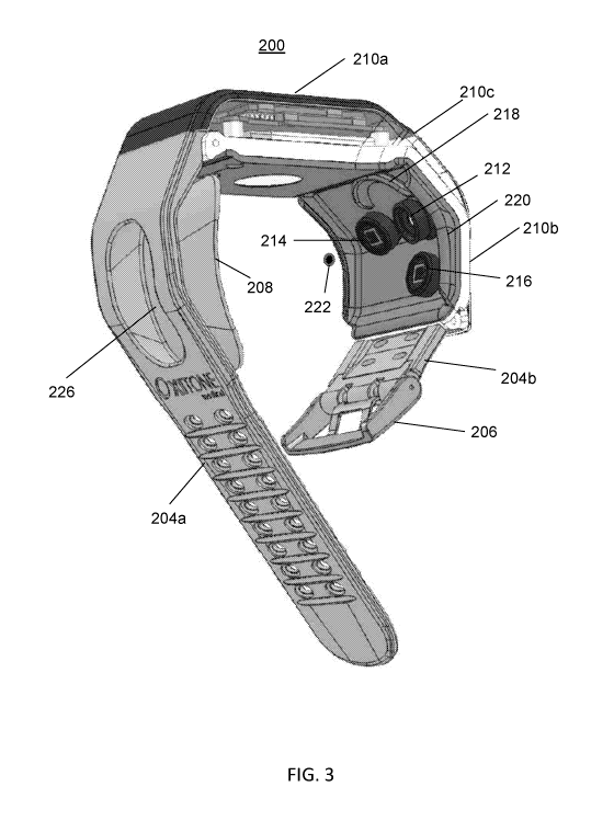
[0030] Figure 3 is perspective view of the wrist-type pulse oximeter of
Figure 2,
illustrating, for example, mechanical features for dampening the effects of a
user's movement
on sensor measurements and for fixating the device to a user's wrist, and
showing a
configuration of light source(s) and detector(s) according to some embodiments
of the present
invention;
[0031] Figures 4A and 4B are side and perspective views, respectively, of
the pulse
oximeter of Figure 2 in accordance with some embodiments of the present
invention;
[0032] Figure 5 is another side view of the pulse oximeter of Figure 2 in
accordance
with some embodiments of the present invention;
[0033] Figures 6A, 6B, and 6C are a side view, and two perspective views,
respectively, of the pulse oximeter of Figure 2 in accordance with some
embodiments of the
present invention;
[0034] Figures 7 and 8 are additional perspective views of the pulse
oximeter of
Figure 2 in accordance with some embodiments of the present invention;
[0035] Figure 9 is a bottom view of the pulse oximeter of Figure 2 in
accordance with
some embodiments of the present invention;
[0036] Figure 10 is a top view of the pulse oximeter of Figure 2 in
accordance with
some embodiments of the present invention;
[0037] Figure 11 is another side view of the pulse oximeter of Figure 2
in accordance
with some embodiments of the present invention;
[0038] Figures 12 and 13 are additional perspective views of the pulse
oximeter of
Figure 2 in accordance with some embodiments of the present invention;
[0039] Figure 14 is an exploded view showing various components of the
pulse
oximeter of Figure 2 in accordance with some embodiments of the present
invention;
7
CA 03047929 2019-06-20
WO 2018/116110 PCT/IB2017/058022
[0040] Figure 15 is a block circuit diagram illustrating hardware
functionality of the
pulse oximeter of Figure 2 in accordance with some embodiments of the present
invention;
[0041] Figure 16 is a graph demonstrating the accuracy of pulse oximetry
data
produced by a pulse oximeter in accordance with Figure 2 according to some
embodiments of
the present invention;
[0042] Figure 17 is a graph demonstrating the accuracy of pulse rate data
produced by
a pulse oximeter in accordance with Figure 2 according to some embodiments of
the present
invention;
[0043] Figure 18 is a graph of PPG signal quality by a pulse oximeter in
accordance
with Figure 2 according to some embodiments of the present invention;
[0044] Figures 19A, 19B, 20A, 20B, 21A, and 21B illustrate embodiments of
light
source configurations for a wrist-worn pulse oximeter according to some
embodiments of the
present invention;
[0045] Figures 22 and 23 illustrate housings for light source(s) and
detector(s)
according to some embodiments of the present invention; and
[0046] Figures 24 through 29 illustrate multiple views of a device (e.g.,
wrist-type
pulse oximeter) in accordance with another embodiment of the present
invention.
DETAILED DESCRIPTION OF ILLUSTRATIVE EMBODIMENTS
[0047] With specific reference now to the drawings in detail, it is to be
understood
that the particulars shown are by way of example and for purposes of
illustrative discussion
of preferred embodiments of the present invention only. The description taken
in conjunction
with the drawings will make apparent to those of ordinary skill in the art how
the several
forms and embodiments of the invention may be embodied in practice.
[0048] It is also to be understood that embodiments of the invention are
not limited in
their application to the details of construction and the arrangement of the
components set
forth in the following description or illustrated in the drawings. Embodiments
of the
invention may be practiced or carried out in various other ways. In addition,
it is to be
8
CA 03047929 2019-06-20
WO 2018/116110 PCT/IB2017/058022
understood that the phraseology and terminology employed herein is for the
purpose of
description and should not be regarded as limiting.
[0049] Turning now to the figures, Figure 2 is a perspective view of a
device 200 in
accordance with an exemplary embodiment of the present invention. Device 200
may be a
wrist-type oximeter device adapted to be worn on a wrist of a user, as further
shown in Figure
2. In some embodiments, device 200 is adapted to obtain data including, for
example, pulse
data, oxygen saturation (SP02) data, and/or other data from a user while the
user wears
device 200 on the wrist. Hence, a user can wear the device 200 in manner
similar to that of
wearing a watch, a wrist band or any article of clothing, ornament, or garment
adapted to be
worn on the wrist of the user. In this manner, a user can wear device 200
while performing
any routine and ordinary operation the user would otherwise perform in
everyday life, such as
walking, running, cycling and so forth. In accordance with embodiments of the
present
technique, device 200 can be conveniently worn at any time or place by those
users required
to or wishing to obtain, for example, pulse oximetry and pulse rate data
without being
attached to elaborate monitoring device or being confined to certain
monitoring areas. Thus,
the device 200 is a self-contained, self-powered device adapted to obtain,
analyze and
process, for example, various light electromagnetic signals from which pulse
oximetry data is
ultimately obtained. Device 200 may further include wired or wireless
interfaces whereby
the device 200 can communicate and/or relay data signals to external and/or
remote devices.
Hence, in some embodiments, device 200 can collect and provide the oximetry
data to any
remote users, institutions such as hospitals or clinics, or anyone who
requires or has interest
in such pulse oximetry data of the user.
[0050] As illustrated in Figure 2, device 200 may include a display 202
that displays,
for example, data measured by device 200. Such data may include pulse rate
data (e.g.,
"PULSE 76"), and data regarding the wearer's blood oxygen saturation of
hemoglobin (e.g.,
"SPO2 97%"). In some embodiments, display 202 may be an LED display, such as,
for
example, an organic light-emitting diode ("OLED") display, liquid crystal
display ("LCD"),
or any other suitable display. In some embodiments, device 200 may include one
or more
physical buttons or user input interfaces (e.g., alphanumerical buttons or
user interface where
by the user can enter any combination of numbers and/or letters as desired or
needed while
the device is in use). Alternatively or additionally, in some embodiments, one
or more
buttons or user interface inputs may be placed at any side, or sides, of
device 200 or any other
9
CA 03047929 2019-06-20
WO 2018/116110 PCT/IB2017/058022
area of device 200 that is accessible to the user. In some embodiments, device
200 may
alternatively or additionally measure and/or display other data, including,
for example, data
regarding one or more vital signs, data regarding one or more blood analytes,
blood pressure
data (e.g., "BP 117/76"), and/or data regarding stroke volume (e.g., "SV 73").
[0051] As further illustrated by Figures 2 and 3, device 200 includes a
wrist strap or
band (204a, 204b) that is adapted to extend around a wearer's wrist. In some
embodiments,
the wrist band may be made up of any flexible and/or stretchable material,
such as rubber,
silicon, soft plastic, or cloth or any combination thereof for providing the
user a comfortable
fit and feeling while wearing the device 200. The wrist band may include first
side 204a
adapted to join with a second side 204b via a clasp 206, which may include,
for example, a
male attachment member for pairing with one or more suitable adjustment holes
formed in
wrist band 204a (as shown) based on the wearer's wrist size, a friction-fit
clasp, or any other
suitable attachment mechanism (e.g., hook and loop or velcro).
[0052] In some embodiments, wrist band 204a may include projection 208.
Projection 208 may be adapted to dampen the effects of a wearer's movement on
sensor
measurements of device 200 and to fixate the device to a wearer's wrist when
the two sides
204a and 204b of the wrist band are joined. In some embodiments, projection
208 may have
an outer surface that is generally concave (see also e.g., Figure 4A, 12, and
14). Such a
contour may enable projection 208, and thus device 200, to fit snugly against
the wearer's
wrist and remain in place even when the wearer is moving. In some embodiments,
projection
208 may include, for example, one or more ridges 224 to further enable device
200 to fit
snugly against the wearer's wrist and remain in place irrespective of whether
the wearer is
moving (see also e.g., Figures 4A, 12 and 14). Projection 208 may be made up
of any
flexible and/or stretchable material, such as rubber, silicon, soft plastic,
or cloth or any
combination thereof for providing the user a comfortable fit and feeling while
wearing the
device 200. For example, in some embodiments, projection 208 may be formed
entirely from
or otherwise include, at least in part (e.g., a coating), an elastomer
material (e.g., silicon)
having a softness (durometer) of between 30 to 75 Shore A (e.g., approximately
50 Shore A).
In some embodiments, projection 208 may be at least partially hollow and may
contain a
space, for example, for storage of emergency medicine such as one or more
pills for
emergency intervention. In some embodiments, projection 208 may be integrally
formed
with or otherwise attached to wrist strap 204a. In some embodiments, wrist
strap 204a may
CA 03047929 2019-06-20
WO 2018/116110 PCT/IB2017/058022
contain an opening or seal 226 through which the emergency medicine may be
inserted and
accessed (see also e.g., Figure 5). The opening or seal 226 may open and close
via any
suitable mechanism, including, for example, a friction fit, a snap fit, a
resealable membrane,
or velcro.
[0053] In some embodiments, wrist straps 204a and 204b may couple to a
casing
(210a, 210b), which may house components including, for example, various
electrical,
mechanical, optical and other devices, such as batteries, processors,
integrated circuit boards,
one or more sensors, one or more light sources such as light emitting diodes,
shunts, and/or
other devices contributing to the functionality and integrity of the device
200. In some
embodiments, display 202 (Figure 2) may be mounted or otherwise fixed to a
first, top
portion 210a of the casing. In some embodiments, top portion 210a of the
casing may house
or otherwise include one or more (e.g., all) of the components in the block
circuit diagram of
Figure 15, described below. In some embodiments, one or more light sources
(e.g., 212),
such as light emitting diodes (LEDs), and/or one or more sensors (e.g., 214
and/or 216), such
as photo diodes, may be mounted to, fixed to, or otherwise housed by a second
portion 210b
of the casing. In some embodiments, the casing (e.g., rigid casing) when
viewed from the
side may be generally L-shaped in that second portion 210b may extend at an
angle relative
to first portion 210a of the casing generally around or at the side of a
wearer's wrist (see also
e.g., Figures 4a and 14). In some embodiments, the casing (210a, 210b) may be
made up of
any suitably strong and durable material, for example, metal or hard plastic,
that is adapted
for housing and protecting components of device 200 from external elements and
forces.
Casing (210a, 210b) may be suitably strong to maintain the positioning of
light source(s) 212
and/or sensor(s) 214 and 216 of device 200. In some embodiments, the casing
(210a, 210b)
simultaneously may have slight pliability or elasticity to act as a movement
dampening
cushion that reduces measurement artifacts of device 200 resulting from
movement of the
wearer. For example, a joining interface (e.g., elbow) 210c between first
portion 210a and
second portion 210b of the casing may allow for slight angular movement
between first
portion 210a and second portion 210b in response to normal forces while device
200 is being
worn by a user. For example, in some embodiments, casing (210a, 210b, 210c)
may be
formed entirely from or otherwise include aluminum and/or thermoplastic
urethane (TPU)
having a durometer of, for example, between 25 Shore A and 35 Shore A (e.g.,
approximately
30 Shore A). In some embodiments, all of portions 210a, 210b, and 210c may be
integrally
11
CA 03047929 2019-06-20
WO 2018/116110 PCT/IB2017/058022
formed together, for example, as shown and described further below in
connection with
Figure 14.
[0054] In some embodiments, device 200 may include structure 218 that
assists to
fixate device 200 at a fixated area corresponding to a distal end of the
wearer's ulna bone,
where the fixated area is used as a measuring area. Structure 218 may be a
curved projection
that is formed generally in the shape of part of a dome or sphere. In some
embodiments, the
measurement is carried out by a one or more sensors or detectors 214 and/or
216 positioned
above or adjacent to the fixated area to detect light emitted by one or more
light sources 212.
For example, the light sources 212 may be two light sources having different
wave lengths
that are located at, above or adjacent to (e.g., at a periphery of) the
fixated area. For example,
light sources 212 may include a red light emitting diode (LED) for emitting
light of
wavelength 660 nm and an infrared LED for mitting light of wavelength 940 nm.
In some
embodiments, one or more of light source(s) 212, detector 214, and detector
216 may include
a generally dome-shaped or conical-shaped structure that assists to fixate
device 200, and its
corresponding light source(s) and sensors, at a fixated area corresponding to
a distal end of
the wearer's ulna bone (see also e.g., Figures 4B and 20A, 20B, 21A, and 21B).
In some
embodiments, device 200 may include only one sensor (e.g., 214 or 216).
[0055] In some embodiments, structure 218 may be part of or integral to a
pad that is
mounted or otherwise fixed generally to an inner side of casing portion 210b.
In some
embodiments, some or all of the pad (e.g., including structure 218) may be
formed entirely
from or otherwise include a flexible and/or stretchable material, such as
rubber, silicon, soft
plastic, or cloth or any combination thereof for providing the user a
comfortable fit and
feeling while wearing the device 200. For example, in some embodiments, the
pad (e.g.,
including structure 218) may be formed entirely from or otherwise include an
elastomer
material (e.g., silicon) having a softness (durometer) of between 30 to 75
Shore A (e.g.,
approximately 50 Shore A), which may be the same material that is used for
projection 208.
In some embodiments, the pad may include one or more barriers (e.g., fins) 220
that function
to, for example, fit snugly against a wearer's wrist and/or to prevent ambient
or stray light
from entering the measuring area when device 200 is worn by a user. The pad
may include,
for example, a first barrier 220 on one side of the pad and a second barrier
on a second,
generally opposite side of the pad. For example, in some embodiments, each
barrier 220 may
be approximately 1 to 5 millimeters wide and extend approximately 1 to 5
millimeters mm
12
CA 03047929 2019-06-20
WO 2018/116110 PCT/IB2017/058022
outward from the user-facing surface of the pad. In some embodiments, the
barriers 220 may
extend along the entire, or any part(s) of, the sides of the pad.
[0056] In some embodiments, each of light source(s) 212 and sensor(s) 214
and/or
216 may generally face generally towards the distal end of the wearer's ulna
bone when the
device is worn by a user. In some embodiments, notwithstanding this general
positioning,
each of light source(s) 212 and sensor(s) 214 and/or 216 may have its own
different and
independent axis, for example, as reflected by unique x, unique y, and unique
z coordinates
and angular orientation relative to a virtual center point 222 of the distal
end of a wearer's
ulna bone (see also e.g., Figures 4A and 4B). In other words, in some
embodiments, the line
of sight or axis relative to the virtual center point 222 of the distal end of
a wearer's ulna
bone is asymmetrical for each of light source(s) 212 and sensor(s) 214 and/or
216. For
example, in such embodiments, even though light source(s) 212 and sensor 214
are generally
adjacent to one another, each has a different axis resulting from the manner
in which each of
212 and 214 is angled generally toward the virtual center point 222 of the
distal end of a
wearer's ulna bone. As another example, even though light source(s) 212 and
sensor 216 are
generally adjacent to one another, each has a different axis resulting from
the manner in
which each of 212 and 214 is angled generally toward the virtual center point
222 of the
distal end of a wearer's ulna bone.
[0057] In some embodiments, reflections of light from light source(s) 212
are
measured by sensor(s) 214 and/or 216 at neither a reflection mode nor a
transmission mode,
but rather at an angle between, for example, 20 and 160 from the emitted
light. This mode,
termed trans-illumination, allows achieving an excellent signal to noise ratio
that for the first
time enables continuous and reliable measurement of oximetry data on the
wrist. The term
"trans-illumination" as used herein, is a mode of optical measurement, in
which the measured
light is reflected off a surface at an angle larger than 0 (which correspond
to simple
reflection) and smaller than 180 (which correspond to simple transmission).
Commonly, but
not exclusively, the reflection angles in trans-illumination mode are between
approximately
20 and approximately 160 . In trans-illumination mode, the measured light is
emitted from
the light source, hits the reflective surface, which may be curved, at an
angle, and is reflected
at an angle to the detector. In practice, trans-illumination includes light
going over various
light paths, having in common an origin in the light source and a measurement
in the
detector. In other embodiments, reflections of light from light source(s) 212
are measured by
13
CA 03047929 2019-06-20
WO 2018/116110 PCT/IB2017/058022
sensor(s) 214 and/or 216 in a reflection mode. In some embodiments,
reflections of light
from light source(s) 212 are measured by one of sensor(s) 214 and/or 216 in a
transillumination mode, and by the other of sensor(s) 214 and/or 216 in a
reflection mode.
[0058] Figures 4A and 4B are side and perspective views, respectively, of
the device
of Figure 2 in accordance with some embodiments of the present invention. In
Figure 4A, the
portions 210a, 210b, and 210c of the casing of device 200 are illustrated from
the side. In
addition, the virtual center point of the distal end of a wearer's ulna bone
is illustrated
schematically as point 222. Viewing device 200 in the direction indicated by
section A-A in
Figure 4A produces the view illustrated in Figure 4B. In Figure 4B, the light
source(s) 212
and sensor(s) 214 and/or 216 are shown generally from the point of view of a
wearer's wrist.
As can be seen, each of 212, 214, and 216 has a different axis resulting from
the manner in
which each of them is angled generally toward the virtual center point 222 of
the distal end of
a wearer's ulna bone.
[0059] Figure 5 is another side view of the device of Figure 2 in
accordance with
some embodiments of the present invention. Figure 5 shows, for example, wrist
strap 204a of
device 200 and opening 226 through which emergency medicine (e.g., one or more
pills) may
be inserted to and accessed from an at least partially hollow portion of
projection 208.
Viewing device 200 in the direction indicated by section B-B in Figure 5
produces the view
illustrated in Figure 4A.
[0060] Figures 6A, 6B, and 6C are an additional side view, and two
perspective
views, respectively, of the device of Figure 2 in accordance with some
embodiments of the
present invention. Viewing device 200 in the direction indicated by section C-
C in Figure 6A
produces the view illustrated in Figure 6B. In some embodiments, device 200
may include
one or more projections 602 (e.g., rounded projections) that function, for
example, to increase
the wearer's comfort and fit of the device to the wearer's wrist. Projections
602 may be
formed entirely from or otherwise include a flexible and/or stretchable
material, such as
rubber, silicon, soft plastic, or cloth or any combination thereof for
providing the user a
comfortable fit and feeling while wearing the device 200. For example, in some
embodiments, projections 602 may be formed entirely from or otherwise include
an
elastomer material (e.g., silicon) having a softness (durometer) of between 30
to 75 Shore A
(e.g., approximately 50 Shore A), which may be the same material that is used
for projection
208 and/or pad 220. In other embodiments, projections 602 may be formed
entirely from or
14
CA 03047929 2019-06-20
WO 2018/116110 PCT/IB2017/058022
otherwise include aluminum and/or thermoplastic urethane (TPU) having a
durometer of, for
example, between 25 Shore A and 35 Shore A (e.g., approximately 30 Shore A),
which may
be the same material as the casing (210a, 210b, 210c). In some embodiments,
projections
602 may be formed integrally with the casing (210a, 210b, 210c).
[0061] Figure 6C illustrates additional details regarding light source(s)
212 and
sensor(s) 214 and/or 216 according to some embodiments of the present
invention. Viewing
device 200 in the direction indicated by section D-D in Figure 6A produces the
view
illustrated in Figure 6C. In some embodiments, the center points between light
source(s) 212
and detector 216 may be approximately 11.3 millimeters (mm) apart. In other
embodiments,
they may be between about 7 to 15 mm apart, or about 8 to 13 mm apart. A
distance between
a center point of light source(s) 212 and an outer ring of light source(s) 212
may be between
1 and 8 mm, or between 1 and 4 mm (e.g., approximately 3.1 mm apart). In some
embodiments, the center points between light source(s) 212 and detector 214
may be
approximately 13.6 millimeters (mm) apart. In other embodiments, they may be
between
about 9 to 17 mm apart, or about 10 to 14 mm apart. In some embodiments,
projection 218
may have a virtual circumference equal to about 19 mm, which may be generally
sufficient to
encompass at least parts of light source(s) 12 and/or detector 214. In other
embodiments, a
virtual circumference of projection 218 may be about 15 to 24 mm and may
depend (e.g., be
selected based on), for example, on the size of the distal end of the ulna
bone of the wearer.
[0062] Figures 7 and 8 are additional perspective views of the device of
Figure 2 in
accordance with some embodiments of the present invention.
[0063] Figure 9 is a bottom view of the pulse oximeter of Figure 2 in
accordance with
some embodiments of the present invention.
[0064] Figure 10 is a top view of the pulse oximeter of Figure 2 in
accordance with
some embodiments of the present invention.
[0065] Figure 11 is another side view of the pulse oximeter of Figure 2
in accordance
with some embodiments of the present invention. In Figure 11, the outermost
part of the
device casing is in phantom view to further illustrate the positioning of
light source(s) 212,
detector 214, and detector 216.
CA 03047929 2019-06-20
WO 2018/116110 PCT/IB2017/058022
[0066] Figures 12 and 13 are additional perspective views of the pulse
oximeter of
Figure 2 in accordance with some embodiments of the present invention. In
these figures, the
outermost part of the device casing and the display 202 are in phantom view to
further
illustrate the positioning of light source(s) 212, detector 214, and detector
216.
[0067] Figure 14 is an exploded view showing various components of the
pulse
oximeter of Figure 2 in accordance with some embodiments of the present
invention. As
shown, in some embodiments, the casing (referenced above as 210a, 210b, and
210c) may
include a first component 1402, second component 1404, and third component
1406. First
component 1402 may be fixed to second component 1404 using one or more screws
1408 or
other fixating devices. In some embodiments, third component 1406 (e.g.,
formed from an
elastomer, for example, the same material as projection 208) may be glued or
otherwise
affixed to second component 1406. Component 1410 (e.g., formed from an
elastomer, for
example, the same material as projection 208) may include various elements for
housing light
source(s) 212, detector 214, and detector 216, where these elements of
component 1410 that
fit through corresponding openings in at least components 1404 and 1406.
Component 1410
may be encased on its other side by component 1402.
[0068] Figure 15 is a block circuit diagram illustrating hardware
functionality of the
pulse oximeter of Figure 2 in accordance with some embodiments of the present
invention.
In general, in some embodiments, device 200 operates to generate red and
infrared optic
signals, which are used for heart rate and SPO2 measurements. To enable these
and other
features of device 200, in some embodiments device 200 is capable of detection
and
measuring of incoming optic signals, movements detection, temperature sensing,
signal
processing, wireless transmission and receipt of data, visual display of at
least heart rate,
SPO2 and battery charge status, haptic alerts, battery operation, and power
and battery
management. Figure 15 includes the following nine building blocks: analog
front end (AFE)
1502, microcontroller unit (MCU) 1504, alerts transducers (haptic) 1506,
sensors (e.g.,
accelerometer, skin temperature and touch) 1508, PPG sensors (e.g., LEDs and
photo-diodes)
1510, display panel 1512, and wireless radio 1514 (e.g., Bluetooth), and power
management
circuit 1516. The device may also include a user push-button or interface
control for, for
example, turning the device On/Off, navigating between screens, and/or
reacting to the
application requests. Additional details in accordance with various
embodiments of the
present invention are provided below.
16
CA 03047929 2019-06-20
WO 2018/116110 PCT/IB2017/058022
[0069] In some embodiments, AFE block 1502 may be a fully-integrated
analog
front-end (AFE) suited for pulse oximeter applications. It may include a low-
noise receiver
channel with an integrated analog-to-digital converter (ADC), an LED transmit
section, and
diagnostics for sensor and LED fault detection. AFE block 1502 may be a
configurable
timing controller. This flexibility may enable the user to control the device
timing
characteristics. To ease clocking requirements and provide a low-jitter clock,
an oscillator
may also be integrated that functions from an external crystal. The AFE block
1502 may
communicate to an external microcontroller or host processor using a suitable
interface, such
as, for example, an SPITM interface.
[0070] The MCU block 1504 according to some embodiments of the present
invention, with its attached memories, may be in charge of all the control and
housekeeping
tasks of device 200 as well as the SPO2 and heart rate signal processing and
calculations.
The MCU block 1504 may store and be configured to run one or more computer
programs
and/or applications. The computer instructions for such programs and/or
applications may be
stored in one or more non-transitory computer readable media of MCU block
1504.
[0071] The alerts transducers 1506 according to some embodiments of the
present
invention may contain one or more haptic transducers that provide haptic
alerts whenever a
fault is encountered or the wearer's SPO2 level goes below a certain level.
[0072] Sensors 1508 according to some embodiments of the present
invention may
include some or all of the following sensors: (i) accelerometer and gyroscope
to provides
movements and position data; (ii) skin temperature sensor to provide skin
temperature data;
and (iii) a touch sensor to detect if the device is attached to a wearer's
wrist or not.
[0073] Display 1512 according to some embodiments of the present
invention may be
an OLED display (e.g., 96 x 96 pixels), and may display the calculated 5P02
and heart-rate
as well as one or more status symbols and error messages.
[0074] Wireless radio 1514 according to some embodiments of the present
invention
may implement one or more suitable wireless communication functionalit(ies)
(e.g.,
Bluetooth 4 (BLE) standard) and may be used to establish one or more
communication
channels between device 200 and, for example, a dedicated control and
monitoring
application (e.g., running on the wearer's mobile device such as a mobile
phone) and/or a
remote monitoring facility accessed via the internet or a cellular
communications network.
17
CA 03047929 2019-06-20
WO 2018/116110 PCT/IB2017/058022
[0075] Power and battery management block 1516 according to some
embodiments
of the present invention may accept a suitable battery (e.g., lithium-ion
polymer battery),
produce all necessary voltages, charge the battery, and monitor the battery
condition.
[0076] Figure 16 is a graph demonstrating the accuracy of pulse oximetry
data
produced by a pulse oximeter in accordance with Figure 2 according to some
embodiments of
the present invention. As shown in Figure 16, there is a tight correlation
(correlation = 0.98;
p-value < 0.0001) between the pulse oximetry data (SP02) derived from a device
generally in
accordance with Figure 2 in some embodiments of the present invention and a
reference
functional arterial oxygen saturation (Sa02) determined by the average of 4
independent CO-
oximeters measurements.
[0077] Figure 17 is a graph demonstrating the accuracy of pulse rate data
produced by
a pulse oximeter in accordance with Figure 2 according to some embodiments of
the present
invention. As shown in Figure 17, there is a tight correlation (correlation =
0.98; p-value <
0.0001) between the pulse rate (PR) derived from a device generally in
accordance with
Figure 2 in some embodiments of the present invention and a reference heart
rate (HR)
determined by a standard electrocardiograph (ECG) device.
[0078] Figure 18 is a graph of PPG signal quality by a pulse oximeter,
for each of red
and infrared light sources, in accordance with a device according to Figure 2
in some
embodiments of the present invention. The y-axis reflects the ratio of the
alternating current
(AC) to direct current (DC) portion of the signal, and the x-axis is time in
seconds.
[0079] Figures 19A, 19B, 20A, 20B, 21A, and 21B illustrate embodiments of
light
source configurations for a wrist-worn pulse oximeter (e.g., configurations
for light source(s)
212 of device 200 in Figure 2) according to some embodiments of the present
invention.
Figures 19A and 19B illustrate the light that passes through a dome-shaped
lens (e.g., 4 or 5
mm dome-shaped lens) that is attached to a light emitting diode (LED) without
space (Figure
19A) or with a 10 micrometer space between them (Figure 19B). As shown, the
light rays
are more concentrated when there is a space between the lens and the LED.
Stray light is
more prevalent when there is no space between the lens and LED.
[0080] Figures 20A and 20B illustrate configurations for a housing for
light source(s)
according to some embodiments of the present invention. As shown, in both
Figures 20A
and 20B the housing includes a raised inner ring 2002 and an outer ring 2004.
In some
18
CA 03047929 2019-06-20
WO 2018/116110 PCT/IB2017/058022
embodiments, the light source(s) (e.g., one or more LEDs) housed by the
structure shown in
Figures 20A and 20B may be placed generally within the area encompassed by
inner ring
2002. In various embodiments, the light source(s) may be positioned below,
equal to, or
above the height of inner ring 2002.
[0081] In
some embodiments, inner ring 2002 may have a height that is greater than
zero but less than or equal to the height (h) of outer ring 2004. For example,
in some
embodiments, the height of the outer ring 2004 may be between about 1
millimeter (mm) (or
less), to about 15 mm (e.g., approximately 4 mm). The height of the inner ring
2002 may be
between about 1 millimeter (mm) (or less) to about 15 mm (e.g., approximately
2 mm). For
example, locating the base of inner ring 2002 at half the height of outer ring
2004 may reduce
stray light by approximately 40%.
[0082] In
some embodiments, the housing contains an inner ring 2002 but no outer
ring 2004. In some embodiments, inner ring 2002 may have a height of zero
(i.e., no inner
ring), in which case the light source(s) housed by the structure may be placed
generally
within the area encompassed by outer ring 2004, and may be positioned in
various
embodiments below, equal to, or above the height of outer ring 2004. In some
embodiments,
a housing is provided that does not contain inner ring 2002 nor outer ring
2004.
[0083]
Figures 21A and 21B each illustrate a configuration for a housing for light
source(s) according to some embodiments of the present invention. They may be
the same as
or similar to the housing(s) shown in Figures 20A and 20B, respectively,
albeit in side view.
As shown, in both the Figure 21A and 21B embodiments the housing is generally
conically-
shaped and extends at an angle. When the angle was increased from about 56.5
degrees to
about 59 degrees (an increase of about 2.5 degrees), stray light from the
light source
decreased by about 80%. In other embodiments, the housing may be at least
partially
cylindrically-shaped. In some embodiments, a maximal diameter of the housing
(measured at
the top of the housing at the outer ring) may be in a range of about 1 mm (or
less) to about 30
mm, or from about 5 mm to about 20 mm (e.g., about 14 mm and making an angle
of about
60 degrees). In some embodiments, the housing may cover adjacent detector(s)
as well (e.g.,
but leaving an opening over the detector(s) as partially shown in Figures 21A
and 21B). In
some embodiments, a diameter of the inner ring may be about 1 mm (or less) to
about 25
mm, or from about 5 mm to about 20 mm (e.g., about 8 mm).
19
CA 03047929 2019-06-20
WO 2018/116110 PCT/IB2017/058022
[0084] Figures 22 and 23 illustrate housings for light source(s) and
detector(s)
according to some embodiments of the present invention. These housings may be
embodiments of component 1410 (Figure 14), where the housings for the light
source(s) and
detector(s) are at least partially cylindrically-shaped. A front side of this
component, which
may be an insert for inclusion within a device (e.g., device 200), where light
is emitted from
is shown in Figure 22. A rear side of this component is shown in Figure 23. In
some
embodiments, such housings may have the general dimensions (e.g., in terms of
height(s) and
diameter(s)) described above in connection with Figures 20A, 20B, 21A, and
21B. In some
embodiments, the inner and outer rings of the housings form a spring-like
configuration (e.g.,
resulting from their collective configuration like a garmoshka and/or in other
embodiments
based on the inclusion of one or more springs). In some embodiments, the
housings may be
elastic, flexible, and spring-like for fixation to a wearer and/or to function
as a damper to
movement (artifacts) and to direct an optical axis of corresponding optical
elements towards
point 222 to maintain a transillumination and/or reflection configuration.
[0085] Figures 24 through 29 illustrate multiple views of a device (e.g.,
wrist-type
pulse oximeter) in accordance with another embodiment of the present
invention. For
example, Figure 24 illustrates that the device may measure and/or display data
regarding
SP02, pulse rate, Bluetooth status, notification (envelope icon) and battery
charge level. In
Figure 26, an opening 2602 (e.g., the same as or similar to opening 226) for
receipt or access
of emergency medication (e.g., one or more pills) may be provided. In some
embodiments,
the device shown in Figures 24 through 29 may be the same as or similar to
device 200
(Figure 2) in all other respects.
[0086] A method of oximetry measurement, according to some embodiments of
the
invention, includes fixating a device at an area above a distal end of the
ulna. This may be
carried out, for example, through the use of projection 218, projection 208,
and/or one or
more dome-shaped projections of light source(s) 212, detector 214, and/or
detector 216.
Thereafter, one or more detectors at, adjacent to, or at a periphery of the
fixated area may
detect reflections of light by the distal end of the ulna, wherein the light
was emitted by one
or more (e.g., at least two) light sources having different wave lengths at,
adjacent to, or at a
periphery of the fixated area. In some embodiments, the detecting and emitting
may be
performed by detector(s) 214 and/or 216, and one or more emitter(s) 212, each
having a
different axis resulting from the manner in which each of them is angled
generally toward a
CA 03047929 2019-06-20
WO 2018/116110 PCT/IB2017/058022
virtual center point 222 of the distal end of a wearer's ulna bone. In some
embodiments, the
method may further include blocking stray light from entering the fixated
area, for example,
by one or more projections 220. In some embodiments, the method may further
comprise
measuring a pulse by reflecting a coherent light source off a bone.
[0087] In the above description, an embodiment is an example or
implementation of
the invention. The various appearances of "one embodiment", "an embodiment" or
"some
embodiments" do not necessarily all refer to the same embodiments.
[0088] Although various features of embodiments of the present invention
may be
described in the context of a single embodiment, the features may also be
provided separately
or in any suitable combination. Conversely, although embodiments of the
present invention
may be described herein in the context of separate embodiments for clarity,
the invention
may also be implemented in a single embodiment.
[0089] Embodiments of the invention may include features from different
embodiments disclosed above, and embodiments may incorporate elements from
other
embodiments disclosed above. The disclosure of elements of some embodiments of
the
invention in the context of a specific embodiment is not to be taken as
limiting their used in
the specific embodiment alone.
[0090] Furthermore, it is to be understood that embodiments of the
invention can be
carried out or practiced in various ways and that embodiments of the invention
can be
implemented in other ways than the ones outlined in the description above.
[0091] The invention is not limited to the diagrams or to the
corresponding
descriptions contained herein. For example, in a method according to some
embodiments of
the present invention, the flow need not move through each illustrated step or
state, or in
exactly the same order as described.
[0092] Meanings of technical and scientific terms used herein are to be
commonly
understood as by one of ordinary skill in the art to which the invention
belongs, unless
otherwise defined.
[0093] While this specification refers to a limited number of
embodiments, these
should not be construed as limitations on the scope of the invention, but
rather as
21
CA 03047929 2019-06-20
WO 2018/116110 PCT/IB2017/058022
exemplifications of some of the preferred embodiments.
Other possible variations,
modifications, and applications are also within the scope of embodiments of
the present
invention.
22