Note: Descriptions are shown in the official language in which they were submitted.
CONTAINER WITH A CHILD-RESISTANT LID
FIELD
[0001] The present disclosure relates to child-resistant containers and in
particular to a container
with a child-resistant lid.
BACKGROUND
[0002] Child-resistant containers allow adult users to store materials which
would be unsafe for
consumption or use by, children, by requiring manipulation of a cap or lid of
the container with
sufficient force to open the container and which a child cannot attain.
Typically, such caps or lids
are circular, requiring rotation of the cap to open the container. However,
such circular caps or lids
have relatively large widths and are not very compact, increasing
manufacturing costs and also
adding bulk to the prOduct. Other child resistant caps or lids are difficult
to use due to the
configuration of the locks.
[0003] Typical child-resistant containers in the prior art also lack
discreetness in that others are
likely to presume that medicine or other substances are contained therein.
Users of those
containers may not wish to have others view the user as being on medication or
having or using
such other substances,
[0004J A need exists, therefore, for a non-traditional, e.g., non-circular cap
or lid for a container,
which is child-resistant, compact, easy to use and discreet.
1
Date Recue/Date Received 2020-11-13
SUMMARY
[0005] The following presents a simplified summary of some embodiments of the
invention in
order to provide a basic understanding of the invention. This summary is not
an extensive overview
of the invention. It is not intended to identify key/critical elements of the
invention or to delineate
the scope of the invention. Its sole purpose is to present some embodiments of
the invention in a
simplified form as a prelude to the more detailed description that is
presented later.
[0006] A child-resistant container of the present invention has a
substantially linear profile with a
longitudinally extending lid on a container body. The lid is opened by moving
a button
longitudinally to disengage an edge portion of an upper member from a lower
member, allowing
a distal end of the upper member to be rotated away from the lower member,
thereby exposing an
aperture for accessing the contents of the container body.
[0007] In one embodiment, the present invention is a lid for a container
having a plurality of first
walls forming an interior. The lid includes a lower member and an upper
member. The lower
member has a plurality of edges forming an aperture for accessing the interior
of the container
when the lid is in an open configuration. The upper member has a distal end; a
hinge rotatably
engaging the lower member wherein the distal end of the upper member rotates
towards the
lower member when the lid is in a closed configuration, and wherein the distal
end rotates away
from the lower member when the lid is in the open configuration; a downwardly
extending
second wall for closing the aperture when the lid is in the closed
configuration, and for opening
the aperture when the lid is in the open configuration; an abutment; a
resilient member engaging
= the abutment; and a protrusion coupled to the resilient member and
engaging a first edge of the
lower member when the lid is in the closed configuration; and a button coupled
to the resilient
member, with the button in a first position for applying an opening force to
the resilient member
2
Date Recue/Date Received 2020-11-13
to move the protrusion away from the first edge to place the lid in the open
configuration, and
with the button in a second position for not applying the opening force to the
resilient member,
wherein a restorative force of the resilient member against the abutment
causes the protrusion to
move toward and engage the first edge of the lower member to place the lid in
the closed
configuration, The abutment includes a central portion engaging the resilient
member. The
abutment includes at least one side portion abutting the central portion for
reinforcing the central
portion. Alternatively, the abutment includes a central portion engaging the
resilient member;
and a pair of side portions laterally abutting the central portion for
reinforcing the central portion.
[0008] In another embodiment, the present invention is a lid for a container
which includes a lower
member and an upper member. The lower member has a side portion engaging an
opening of the
container; and an interior portion forming an aperture operatively connected
to an interior of the
container. The upper member has a rear portion having a hinge rotatably
coupled to the lower
member; and a front portion having a slidable member with a first detent for
engaging the interior
portion; and a base for complementarily resting in the aperture, thereby
closing the container.
Sliding movement of the slidable member in a longitudinal direction causes the
first detent to
disengage from the interior portion to allow the upper member to rotate about
the hinge to move
the front portion away from the lower member, thereby opening the container.
The side portion
removably engages the opening of the container. The side portion has a second
detent for
frictionally engaging a side of the container, thereby retaining the lower
member in a coupled
engagement with the container. The upper member includes a button connected to
the slidable
member, and responsive to a sliding force for sliding the slidable member
longitudinally toward
the rear portion. The button includes a ridge for allowing a user to grip the
button to apply the
sliding force. The front portion includes an abutment; and a resilient member
contacting the
3
Date Recue/Date Received 2020-11-13
abutment and connected to the slidable member for biasing the slidable member
longitudinally
away from the rear portion. The resilient member biases the slidable member to
apply a restorative
force opposite to the sliding force. The resilient member restores the
slidable member to an initial
position when the sliding force is not applied to the button.
[00091 In a further embodiment, the present invention is a box which includes
a container having
an opening on one side; and a lid. The lid includes a lower member and an
upper member. The
lower member has a side portion engaging the opening of the container; and an
interior portion
forming an aperture operatively connected to an interior of the container. The
upper member has
a rear portion having a hinge rotatably coupled to the lower member; and a
front portion having a
slidable member with a first detent for engaging the interior portion; and a
base for
complementarily resting in the aperture, thereby closing the container;
wherein sliding movement
of the slidable member in a longitudinal direction causes the first detent to
disengage from the
interior portion to allow the upper member to rotate about the hinge to move
the front portion away
from the lower member, thereby opening the container. The side portion
removably engages the
opening of the container. The side portion has a second detent for
frictionally engaging a side of
the container, thereby retaining the lower member in a coupled engagement with
the container.
The upper member includes a button connected to the slidable member, and
responsive to a sliding
force for sliding the slidable member longitudinally toward the rear portion.
The button includes a
ridge for allowing a user to grip the button to apply the sliding force. The
front portion includes an
abutment; and a resilient member contacting the abutment and connected to the
slidable member
for biasing the slidable member longitudinally away from the rear portion. The
resilient member
biases the slidable member to apply a restorative force opposite to the
sliding force. The resilient
4
Date Recue/Date Received 2020-11-13
member restores the slidable member to an initial position when the sliding
force is not applied to
the button.
BRIEF DESCMPTION OF DRAWINGS
[0010] The foregoing siimmaxy, as well as the following detailed description
of presently preferred
embodiments of the invention, will be better understood when read in
conjunction with the
appended drawings. For the purpose of illustrating the invention, there are
shown in the drawings
embodiments which are presently preferred. It should be understood, however,
that the invention
is not limited to the precise arrangements and instrumentalities shown.
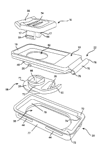
[0011] In the drawings:
[0012] FIG. I is a top front side perspective view of the container of the
present invention;
[0013] FIG. 2 is a top plan view of the container;
[0014] FIG. 3 is a top side perspective view of the container with the lid in
an open configuration;
[0015] FIG. 4 is a top front side perspective view of the container without
the lid;
[0016] FIG. 5 is a top front perspective view of the container without the
lid;
[0017] FIG. 6 is a top front side perspective view of the lid in an open
configuration;
[0018] FIG, 7 is a bottom rear side perspective view of the lid in the open
configuration;
[0019] FIG. 8 is a bottom rear perspective view of the lid in a closed
configuration;
[0020] FIG, 9 is a front plan view of the lid in the closed configuration;
[0021] FIG. 10 is a top view of a lid of an alternative embodiment in a closed
configuration with
all parts of the lid superimposed;
[0022] FIG. 11 is a top tear side perspective view of the lid of FIG. 10 in
the closed configuration;
[0023] FIG. 12 is a rear plan view of the lid of FIG. 10 in the closed
configuration;
Date Recue/Date Received 2020-11-13
[0024j FIG. 13 is a side plan view of the lid of FIG. 10 in the closed
configuration;
[0025] FIG. 14 is a top side rear perspective view of the lid of FIG. 10 with
parts separated;
[0026] FIG. 15 is a top side front perspective view of a body of a bottom
member; and
[0027] FIG. 16 is a top side front perspective view of a lower member.
[00281 To facilitate an understanding of the invention, identical reference
numerals have been
used, when appropriate, to designate the same or similar elements that are
common to the figures.
Further, unless stated otherwise, the features shown in the figures are not
drawn to scale but are
shown for illustrative purposes only.
DETAILED DESCRIPTION
[00291 Certain terminology is used in the following description for
convenience only and is not
limiting. The article "a" is intended to include one or more items, and where
only one item is
intended the term "one" or similar language is used. Additionally, to assist
in the description of
the present invention, words such as top, bottom, side, upper, lower, front,
rear, inner, outer, right
and left may be used to describe the accompanying figures, The terminology
includes the words
above specifically mentioned, derivatives thereof, and words of similar
import.
[0030] As shown in FIG. 1, the container 10 of the present invention includes
a child-resistant lid
12 which longitudinally extends along the length of a container body 14. The
lid 12 is removably
mounted on the container body 14, with the child-resistant lid 12 having a
movable button 16 for
unlocking and opening the lid 12. FIG. 2 is a top plan view of the container
10 with the lid 12
removably mounted to the container body 14 and having the movable button 16
which moves
longitudinally within a cavity 50 on an upper portion of the lid 12, At least
one ridge 54 and/or a
front detent 56 extend upward from the button 16, allowing a user to more
easily grip and move
6
Date Recue/Date Received 2020-11-13
the button 16 longitudinally within the cavity 50. As shown in FIG. 3, a
bottom portion of the
button 16 includes a pair of extensions 17 integrally formed with the button
16 and extending
downwardly therefrom.
1011311 FIG. 3 is a top side perspective view of the container 10 with the lid
12 in an open
configuration. The lid 12 has an upper member 18 rotatably mounted to a lower
member 20 by a
hinge 22. The hinge 22 may be a rotatable coupling of the upper member 18 to
the lower member
20. Alternatively, the hinge 22 may be a resilient joint integrally coupling
the members 18, 20
together. The upper member 18 includes a base 46 in the form of a downwardly
extending wall
forming a slot 60 for housing the button extensions 17 and a bottom member 24.
Referring to
FIGS. 3, 6, and 8, the base 46 includes an abutment 31 extending transversely
between the base
walls while protrusions 26 extend outward laterally from the base walls 46.
The abutment 31
includes a central portion 32 engaging a resilient member 30, and a pair of
side portions 33 laterally
abutting the central portion 32 for reinforcing the structure of the central
portion 32 as the resilient
member 30 applies a force to the central portion 32, as described below.
[0032] As shown in FIG. 3, the bottom member 24 includes an aperture 48 and
resilient members
28, 30 extend therefrom, with a first resilient member 28 slidably engaging
the second resilient
member 30, and the second resilient member 30 slidably engages at least the
central portion 32 of
the abutment 31 by applying a force to the central portion 32, such that the
resilient members 28,
30 bias the bottom member 24 and the button 16 longitudinally away from the
abutment 31 and/or
the hinge 22. The bottom member 24 is attached to the button 16 by
frictionally engaging the
button extensions 17 which extend through the bottom member aperture 48. The
bottom member
24 moves longitudinally parallel to the length of the upper member 18 as the
movable button 16 is
moved by the finger of a user using, for example, the at least one ridge 54
andlor the front detent
7
Date Recue/Date Received 2020-11-13
56, shown in FIG. 2. The bottom member 24 includes a top edge 25 opposite the
resilient members
28, 30.
[0933] Still referring to FIG. 3, the lower member 20 has front and rear edges
34, a first side edge
35, and a second side edge 37 forming an aperture 36, allowing items kept
within the interior of
the container body 14 to be removed through the aperture 36 when a distal end
19 of the upper
member 18 is rotated away from the lower member 20 to be in the open
configuration of the lid
12. The edges 34 engage the protrusions 26, such that the protrusions 26 lock
the upper member
18 to the lower member 20 in a friction ft when the upper member 18 is rotated
downward to fit
within the aperture 36 in the lower member 20, as shown in FIG. 8. As well,
the bottom member
top edge 25 extends beyond the base 46 above the first side edge 35 when the
button 16 is
disengaged, as shown for example in FIGS. 3, 6 and 8.
[00341 The purpose of the protrusions 26 shown in FIGS. 3, 6, 8, and 14
provides an additional
level of lifting needed to open the lid 12. Without the protrusions 26, one
may simply pull on the
button 16 or slide the front detent 56, which is too easy for children to
open. By adding the
protrusions 26, the additional pressure from the protrusions 26 makes for a
two-step, slide-and-
pull-up opening, rather than just a slide opening or just a pull opening. The
added protrusions 26
provide enough friction and enough needed cognitive ability from children such
that testing
showed a 94% Child-Resistant Effectiveness.
f0035j FIGS. 4-5 are perspective views of the container body 14 without the
lid 12, in which the
container body 14 has an upper edge 38 and a lip 39 extending inwardly below
the upper edge 38.
The lip 39 is formed as at least a protrusion extending at least partially on
or about the upper edge
38. The container body 14 also includes an interior 40 for receiving or
dispensing items through
the aperture 36 of the lid 12, as shown in FIGS. 3 and 6-7. Accordingly, the
lip 39 may extend
8
Date Recue/Date Received 2020-11-13
entirely around the perimeter formed by the upper edge 38. Alternatively, the
lip 39 may only
extend partially around the perimeter formed by the upper edge 38.
[0036] As shown in FIG. 6-7 and 14, the lid 12 has an outer edge 42 for
resting on the upper edge
38 of the container body 14, and the lid 12 further includes front and rear
detents 44 disposed on
a side portion 77 of the lower member 20 for engaging a bottom portion of the
lip 39 of the
container body 14 in a friction fit, such that the container body 14 retains
the lid 12 thereupon. In
an alternative embodiment, shown in FIGS. 10-14, the lid 12 includes
additional side detents 52
disposed on the side portion 77 for further securing the lid 12 to the
container body 14. In a further
alternative embodiment, the detents 44, 52 may engage respective portions of
the lip 39 which do
not entirely extend around the perimeter of the upper edge 38.
[0037] Referring to FIGS. 6-8 and 14, the bottom member 24 slidably engages
the base 46 of the
upper member 18, with the bottom member 24 operatively connected to the button
16 via
extensions 17 through the bottom member aperture 48, shown for example in
phantom in FIG. 10.
When the button 16 is pushed longitudinally by the user towards the abutment
31 and/or the hinge
22, the bottom member 24 moves towards the abutment 31 within a slot 60 and
compresses the
resilient members 28, 30, while the top edge 25 of the bottom member 24 is
substantially aligned
with the base 46, allowing the upper member 18 to be pivoted away from the
lower member 20 to
have the upper member 18 in an open configuration with the aperture 36 which
extends through
the interior portion 79 of the lower member 20, such that the aperture 36 is
cleared of the lid 18,
as shown in FIGS. 3 and 6-7. As well, the protrusions 26 are disengaged from
the edges 34.
[0038] Referring to FIGS. 8 and 14, subsequent release of the button 16 by the
user will allow the
restorative force of the resilient members 28, 30 to move the bottom member 24
and the button 16
longitudinally away from the abutment 31 and/or the hinge 22, and to move the
top edge 25 to
9
Date Recue/Date Received 2021-06-15
engage a lower surface of the first side edge 35 when the upper member 18 is
pivoted toward the
lower member 20 to close the aperture 36 extending through the interior
portion 79, while the
protrusions 26 engage lower surfaces of the front and rear edges 34, thereby
locking the upper
member 18 to the lower member 20 to close and lock the lid 12. FIG. 8 is a
bottom rear perspective
view of the lid 12 in a closed configuration, with the top edge 25 of the
bottom member 24
engaging the first side edge 35 while the resilient members 28, 30 apply a
restorative force to the
bottom member 24 directed away from the abutment 31 and/or the hinge 22.
[0039] FIGS. 10-13 show an alternative embodiment of the lid 12 in the closed
configuration with
the front and rear detents 44, and the side detents 52 extending from walls of
the lower member
20 of the lid 12. An example height of the lid 12 is about .775 cm (about .305
inches). The button
16 may include the front detent 56 extending upward from the button 16, and
the button 16 may
also include at least one ridge 54 for gripping by a user to open the lid 12
as the button 16 is pushed
back toward the hinge 22. FIG. 10 is a top view of the lid 12 in the closed
configuration, showing
the components of the lid 12 in phantom, including the slot 60 on the bottom
portion of the upper
member 18 in which the button 16 moves longitudinally within the cavity 50 on
the top portion of
the upper member 18, shown in FIGS. 2 and 10-11. The longitudinal length of
the lid 12 is, for
example, about 3.787 cm (about 1.491 inches), and the width of the lid 12 is,
for example, about
1.885 cm (about .742 inches). As shown in FIG. 10, the abutment 31 extends
from opposing walls
of the base 46, with the resilient member 30 engaging the central portion of
the abutment 32.
[0040] FIG. 14 is a top side rear perspective view of the lid 12 of FIG. 10
with parts separated,
showing the lid 12 having the button 16 insertable into an aperture 62 of the
upper member 18,
with tabs 64 on a lower portion of the extensions 17 of the button 16. The
tabs 64 are capable of
engaging a body 66 having the resilient members 28, 30 and forming the bottom
member 24. The
Date Recue/Date Received 2021-06-15
tabs 64 are inserted into and are retained by a slot 68 in the body 66 in a
force-fit engagement. The
hinge 22 of the upper member 18 is capable of being inserted into and retained
by at least one
hinge slot 74 in the lower member 20 in a force-fit engagement.
[0041] FIG. 15 is a a top side front perspective view of the body 66 of the
bottom member 24 in
greater detail. The body 66 has a member 70 with the slot 68 therein, and with
the resilient
members 28, 30 extending from the rear of the member 70. A lower portion 71
extends downward
from the member 70, with the lower portion 71 having the top edge 25 which
extends beyond the
base 46 above the first side edge 35, as shown in FIGS. 6 and 8.
[0042] FIG. 16 is a top side front perspective view of the lower member 20 in
greater detail, with
upper detents 72 and lower detents 73 forming respective hinge slots 74
proximal to the second
side edge 37. Referring to FIG. 14, the hinge 22 includes hinge ends 76 of a
hinge rod 78. The
hinge slots 74 in FIG. 16 receive respective hinge ends 76 of the hinge rod
78, as shown in FIG.
14, in a snap-in engagement such that the hinge ends 76 rotatably engage the
respective hinge slots
74, thus forming the rotatable hinge 22 as shown in FIGS. 3 and 10.
[0043] The container body 14 of the present invention is preferably
constructed of tin but could
be made from other metals or plastic. The components associated with the lid
12 are preferably
constructed of injection molded plastic but also could be constructed of
various metals. As
described above, the container 10 of the present invention requires very few
components and
therefore manufacturing costs are greatly reduced. Also, the invention
configuration of the
container 10 allows a user to easily open the container 10 while maintaining a
child resistant
enclosure when in a locked configuration. As well, the present invention
provides a discreet
container that is child-resistant.
11
Date Recue/Date Received 2021-06-15
[0044] The present invention may be embodied in other specific forms without
departing from its
spirit or essential characteristics. The described embodiments are to be
considered in all respects
only as illustrative and not restrictive. The scope of the invention,
therefore, will be indicated by
claims rather than by the foregoing description. All changes, which come
within the meaning and
range of equivalency of the claims, are to be embraced within their scope.
12
Date Recue/Date Received 2021-06-15