Note: Descriptions are shown in the official language in which they were submitted.
SOLVENT PRODUCTION CONTROL METHOD
IN SOLVENT-STEAM PROCESSES
FIELD
[0001] The present disclosure relates generally to hydrocarbon recovery,
and
particularly to a solvent production control method in solvent-steam
processes.
BACKGROUND
[0002] Hydrocarbon resources such as bituminous sands (also commonly
referred to
as oil sands) present significant technical and economic recovery challenges
due to the
hydrocarbons in the bituminous sands having high viscosities at initial
reservoir
temperature. Some subterranean deposits of heavy hydrocarbons can be extracted
in
situ by increasing the mobility of the heavy hydrocarbons so that they can be
moved to,
and recovered from, a production well (also referred to as producer)
penetrating a
formation of the hydrocarbons. Reservoirs of such deposits may be referred to
as
reservoirs of heavy hydrocarbons, heavy oil, bitumen, tar sands, bituminous
sands, or
oil sands. For example, such reservoirs include deposits as may be found in
Canada's
Athabasca oil sands.
[0003] The in situ processes for recovering oil from heavy hydrocarbon
reservoirs
typically involve the use of one or multiple wells drilled into the reservoir,
and are
assisted or aided by injecting a heated fluid such as steam or solvent into
the reservoir
formation from an injection well (also referred to as injector).
[0004] For example, a known in situ process for recovering viscous
hydrocarbons is
the steam-assisted gravity drainage (SAGD) process. A typical (conventional)
SAGD
process utilizes one or more pairs of vertically spaced horizontal wells. For
example,
various embodiments of the SAGD process are described in CA 1,304,287 and
related
US 4,344,485.
CA 3048579 2019-07-04
[0005] In a SAGD process, steam is injected through an upper, horizontal,
injection
well into a viscous hydrocarbon reservoir while hydrocarbons are produced from
a
lower, parallel, horizontal, production well vertically spaced proximate to
the injection
well. The injection and production wells are typically located near, but some
distance
above, the bottom of a pay zone in the hydrocarbon deposit. The injected steam
initially
heats and mobilizes the in situ hydrocarbons in the reservoir around the
injection well.
Mobilized hydrocarbons will drain downward due to gravity, leaving a volume of
the
formation at least partially depleted of the hydrocarbons. The pores in the
depleted
volume of the formation, from which mobilized oil has at least partially
drained, are then
filled with fluids containing mainly injected steam, and the depleted volume
is thus
commonly referred to as the "steam chamber". As steam injection and gravity
drainage
continue, the steam chamber will continue to grow, expanding both upwardly and
laterally from the injection well. As the steam chamber expands upwardly and
laterally
from the injection well, more and more viscous hydrocarbons in the reservoir
are
gradually heated and mobilized, especially at the margins of the steam chamber
where
the steam condenses and heats a layer of viscous hydrocarbons by thermal
conduction.
The mobilized hydrocarbons (and aqueous condensate) drain under the effects of
gravity towards the bottom of the steam chamber, where the production well is
located.
The mobilized hydrocarbons are collected and produced from the production
well. In a
SAGD process, additional injection or production wells, such as a well drilled
using
Wedge WellTM technology, may also be provided.
[0006] Alternative processes aided by fluids other than steam have also been
proposed. For example, solvent-aided processes (SAP) and a process known as
the
vapour-extraction (VAPEX) process have been proposed. In SAP, both steam and a
solvent may be used to aid recovery. VAPEX utilizes a solvent vapour, instead
of
steam, to reduce the viscosity of viscous hydrocarbons. In a proposed VAPEX
process,
a solvent, such as propane, is injected into the reservoir in the vapour
phase, to form a
vapour-filled chamber within the reservoir. The solvent vapour dissolves in
the oil
around the vapour chamber and the resulting solution drains, driven by
gravity, to a
horizontal production well placed low in the formation. The solvent vapour, at
or near its
dew point, is injected simultaneously with hot water from a horizontal well
located at the
2
CA 3048579 2019-07-04
top of the reservoir. See, Butler et al., "A New Process (VAPEX) for
Recovering Heavy
Oils Using Hot Water and Hydrocarbon Vapour", Journal of Canadian Petroleum
Technology, 1991, vol. 30, issue 1, pages 97-106.
[0007] US 6,662,872 discloses a combined steam and vapour extraction
process
(SAVEX), where steam is injected until an upper surface of the steam chamber
has
progressed to 25 to 75 percent of the distance from the bottom of the
injection well to
the top of the reservoir, or until the recovery rate of hydrocarbons is about
25 to 75
percent of the peak predicted recovery rate using SAGD. When the condition is
met,
steam injection is suspended and replaced with solvent vapour injection (the
VAPEX
process). One of the goals in modifying existing SAGD and other steam-assisted
processes is to reduce the steam to oil ratio (SOR) or the cumulative SOR
(CSOR), as
the SOR or CSOR is commonly considered an important metric for assessing the
performance and efficiency of a steam-assisted recovery process. Replacing
steam with
solvent vapour and hot water as in the VAPEX or SAVEX process is expected to
reduce
CSOR. However, another important measure of the performance of an oil recovery
process is the oil production rate, which indicates how fast oil can be
produced from the
reservoir. The proposed VAPEX or SAVEX processes are expected to result in
significant reduction in peak oil production rate.
[0008] It has also been proposed in CA 2,893,221 to inject both steam and a
diluting
agent to assist hydrocarbon recovery from bituminous sands. For example, it
has been
suggested that a mobilizing composition comprising 75-98 vol% diluting agent
and 2-25
vol% steam at the standard temperature and pressure (STP) may be used in a
gravity
drainage process for recovering viscous oil from an underground reservoir.
Bench-scale
gravity drainage tests and simulation tests were performed using n-heptane and
pentane as the diluting agents. The results were assessed based on the
cumulative
bitumen recovery, cumulative injected diluting agent, and diluting agent left
in the
reservoir.
[0009] CA 2,956,771 discloses a hybrid recover process to recover heavy
hydrocarbons from a subterranean reservoir, which includes steam-dominant and
3
CA 3048579 2019-07-04
solvent-dominant processes. In the steam-dominant process, the weight
percentage of
steam in the injection fluid is more than about 70 wt%. In the solvent-
dominant process,
a solvent and steam are co-injected into the vapour chamber, where the weight
ratio of
co-injected solvent vapour to co-injected steam is higher than 3/2. The
solvent may
include propane, butane, pentane, hexane, heptane, or octane. When propane is
used
as the solvent, the weight percentage of propane in the co-injection mixture
may be
higher than 70 wt%.
[0010] Instead of a well pair, one or more single horizontal well or
vertical wells may
be utilized for injection and production in in situ hydrocarbon recovery
processes such
as, but not limited to, SAGD, SAP, cyclic steam stimulation (CSS), or fluid
flooding
processes. For example, CA 2,844,345 discloses a single vertical or inclined
well
thermal recovery process. CA 2,868,560 discloses a single horizontal well for
injection
and production in thermal or solvent recovery processes. These single well
processes
may be preceded by start-up acceleration techniques to establish communication
in the
formation between openings in the single well that have been configured to
allow for
both injection and production. An assembly for coupling a high-pressure steam
pipeline,
a produced hydrocarbon emulsion pipeline, and a produced gas pipeline to a
single well
may be employed for facilitating injection and production.
[0011] In the aforementioned recovery processes or techniques where a
solvent is
used, the injected solvent may be recovered with oil through the production
well, but it is
difficult to control the solvent recovery without significantly impact on the
oil production
rate.
SUMMARY
[0012] In one aspect, the present disclosure relates to a method for
producing
hydrocarbons from a subterranean reservoir, comprising: injecting steam and a
solvent
into the reservoir to mobilize viscous hydrocarbons in the reservoir, wherein
mobilized
hydrocarbons drain towards a production zone, the production zone comprising a
liquid
4
CA 3048579 2019-07-04
phase comprising water and mobilized hydrocarbons, and a gas phase comprising
the
solvent; producing a fluid comprising the liquid phase and the gas phase,
through a
production well, the production well penetrating the liquid phase in the
production zone;
controlling a ratio of produced gas phase to produced liquid phase in the
produced fluid,
wherein the controlling comprises adjusting a flow rate of the fluid in the
production well
so as to raise or lower a liquid level of the liquid phase surrounding the
production well,
thus reducing or increasing flow of the solvent in the gas phase into the
production well
through the liquid phase in the production zone.
[0013] In an embodiment of a method described herein, the fluid is pumped
through
the production well and the flow rate is adjusted by altering a pump speed in
the
production well.
[0014] In an embodiment of a method described herein, the pump speed is
reduced
by less than about 5% to reduce the ratio of produced gas phase to produced
liquid
phase by more than about 30%.
[0015] In an embodiment of a method described herein, the flow rate is
adjusted by
altering a downhole pressure in the production well.
[0016] In an embodiment of a method described herein, altering the downhole
pressure comprises adjusting a valve downstream of the production well.
[0017] In an embodiment of a method described herein, the flow rate is
controlled to
maintain the production temperature of the produced fluid at about 20 C to
about 80 C
below the injection temperature.
[0018] In an embodiment of a method described herein, the solvent comprises
propane, the injection temperature is about 120 C to about 245 C and the
production
temperature is about 100 C to about 225 C.
[0019] In an embodiment of a method described herein, the production
temperature
is about 165 C to about 205 C.
[0020] In an embodiment of a method described herein, the production
temperature
CA 3048579 2019-07-04
is at least about 140*c.
[0021] In an embodiment of a method described herein, the production
temperature
is a temperature at a heel of the production well.
[0022] In an embodiment of a method described herein, the flow rate is
controlled
such that the liquid level is about 2 m to about 8 m above the production
well.
[0023] In an embodiment of a method described herein, the flow rate is
controlled
such that the liquid level is about 3 m to about 4 m above the production
well.
[0024] In an embodiment of a method described herein, the produced fluid
comprises an emulsion.
[0025] In an embodiment of a method described herein, the gas phase further
comprises at least one of steam and a non-condensable gas.
[0026] In an embodiment of a method described herein, the mobilized
hydrocarbons
drain downward into the production zone.
[0027] In an embodiment of a method described herein, the weight ratio of
the gas
phase to the liquid phase in the produced fluid is from about 1/16 to about
1/5.
[0028] In an embodiment of a method described herein, comprising adjusting
the
flow rate of the fluid in the production well to set the production well
temperature at
182 C to 195 C.
[0029] In an embodiment of a method described herein, the weight ratio of
injected
solvent to injected steam is 1/19 to 9/1.
[0030] In an embodiment of a method described herein, the weight ratio of
injected
solvent to injected steam is 1.2 to 1.9.
[0031] In an embodiment of a method described herein, the flow rate is
adjusted so
that the weight ratio of injected solvent to produced solvent is 0.5 to 0.7.
6
CA 3048579 2019-07-04
[0032] In an embodiment of a method described herein, the flow rate is
adjusted so
that the weight ratio of injected solvent to produced solvent is 0.4 or lower.
[0033] In an embodiment of a method described herein, the solvent comprises
one
or more C1-12 alkanes, a natural gas liquid, a condensate, a diluent, or a
mixture thereof.
[0034] In an embodiment of a method described herein, wherein the liquid
phase
comprises water, mobilized hydrocarbons and the solvent.
[0035] Other aspects, features, and embodiments of the present disclosure
will
become apparent to those of ordinary skill in the art upon review of the
following
description of specific embodiments of the disclosure in conjunction with the
accompanying figures.
BRIEF DESCRIPTION OF THE DRAWINGS
[0036] In the figures, which illustrate, by way of example only,
embodiments of the
present disclosure:
[0037] FIG. 1 is a schematic side view of a hydrocarbon reservoir and a
pair of wells
penetrating the reservoir for recovery of hydrocarbons.
[0038] FIG. 2 is a schematic partial end view of the reservoir and wells of
FIG. 1. -
[0039] FIG. 3 is a schematic perspective view of the reservoir and wells of
FIG. 1
during operation after a vapour chamber has formed in the reservoir.
[0040] FIG. 4 is a schematic partial section view of the wells and the
vapour
chamber in the reservoir of FIG. 3 showing a low inventory of liquid
surrounding the
production well.
[0041] FIG. 5 is a schematic partial section view of the wells and the
vapour
chamber in the reservoir of FIG. 3 showing a high inventory of liquid
surrounding the
production well.
7
CA 3048579 2019-07-04
[0042] FIG. 6 is a data graph showing casing gas flow, oil production and
pump
speed in a solvent-steam process.
[0043] FIG. 7 is a schematic side view of a production well with a pump
configured
for pumping fluid through the production well.
[0044] FIG. 8 is a schematic side view of a well pair illustrating typical
elevation
changes of the horizontal sections of the injection well and production well.
[0045] FIG. 9 is a graph showing casing gas flow and pump speed in an
example
solvent-steam process before reducing pump speed.
[0046] FIG. 10 is graph showing casing gas flow and pump speed in a solvent-
steam
process after reducing pump speed.
[0047] FIG. 11 is a line graph illustrating possible liquid level
variations in the
production zone between the production well for a SAGD process and a solvent-
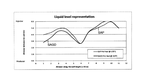
steam
process, respectively, based on simulation results.
[0048] FIG. 12 is a graph showing representative simulation results of the
dependence of the production well heel temperature on pump speed in the SAGD
and
solvent-seam processes respectively.
[0049] FIG. 13 is a graph showing representative simulation results of
instantaneous
steam-oil ration (iSOR) and cumulative SOR (cSOR) at different production well
heel
temperatures in a simulated propane-steam process.
[0050] FIG. 14 is a graph showing representative simulation results of rate
uplift and
cSOR at different production well heel temperatures in the propane-steam
process.
[0051] FIG. 15 is a graph showing the same simulation results shown in FIG.
14 with
the production well heel temperature as the x-axis variable.
8
CA 3048579 2019-07-04
DETAILED DESCRIPTION
[0052] In brief overview, the present inventors have discovered that a
fluid produced
from a subterranean reservoir in a solvent-steam process, the ratio of
produced gas
phase to produced liquid phase can be controlled by adjusting the flow rate of
the fluid
in the production well. In particular, the flow rate of the fluid in the
production well may
be adjusted so as to raise or lower the liquid level of the liquid phase
surrounding the
production well, thus reducing or increasing flow of the solvent in the gas
phase into the
production well through the liquid phase in the production zone.
[0053] For example, the flow rate of the fluid may be adjusted by adjusting
the fluid
flow pumping speed in the production well. In particular, decreasing the pump
speed
can result in increased inventory of liquid (and hence a higher liquid level)
around the
production well and reduced production of solvent in the gas phase.
Conversely,
increasing the pump speed can result in reduced inventory of liquid around the
production well (and hence a lower liquid level) and increased production of
solvent in
the gas phase.
[0054] Simulation and test results have shown that the solvent gas
production rate
can be quite sensitive to the pump speed. For example, in an example propane-
steam
process, test results showed that the ratio of produced gas phase to produced
liquid
phase could be reduced by more than 30 vol% (volume percent) when the pump
speed
was reduced by less than about 5% and the ratio was calculated based on the
daily
averages of the production rates. Moreover, it has been observed that the
reduction of
5% in pump speed did not significantly affect the oil production rate.
[0055] It is quite unexpected that it is possible to recover the solvent in
the gas
phase with a controllable rate through the liquid phase in a solvent-steam
process.
[0056] As comparison, in a SAGD process, it is expected that little steam
could be
produced in the gas phase if the liquid level in the production zone is above
the
production well, but if the liquid level drops too low a surge of the steam
production rate
("short circuit") would occur. It is expected that steam would condense in the
liquid
9
CA 3048579 2019-07-04
phase and be produced as water if the liquid level is high, and can only be
produced in
a large amount if there is a gas phase passage through the production well
(hence the
"short circuit").
[0057] Thus, an embodiment of the present disclosure relates to a method of
controlling the recovery of injected solvent by controlling the flow rate
through the
production well, such as by adjusting the pumping speed of a pump in the
production
well, or by adjusting the pressure differential between the injection well and
the
production well, which also affects the liquid level around the production
well.
[0058] Further, if the pump speed can be reduced and the pump is
consequently
operated at a lower temperature when it is not necessary to maintain a higher
speed in
order to achieve the production targets, the pump life may be prolonged.
[0059] The flow rate of the fluid in the production well may also be
adjusted by
altering the emulsion pressure at the discharge port of the pump (also known
as the
"backpressure") in the production well that is used to control the liquid
(such as
emulsion) flow through the production well. The backpressure of the pump can
be
altered through the manipulation of a choke valve, such as an inline globe
valve. By
either closing or opening the choke valve, the backpressure on the pump will
be
increased or decreased, respectively. By managing the backpressure, this will
allow the
pump to operate at its Best Efficiency Point (BEP) while the pump speed is at
significantly different rates. Operating the pump at the manufacturer
recommended BEP
can increase the life expectancy of the pump and reduces the likelihood of
undesirable
pump trip conditions. Increasing the backpressure will limit liquid flow
resulting in a
higher liquid level of the liquid phase surrounding the production well and
reduced
production of solvent in the gas phase. Conversely, decreasing the
backpressure will
increase liquid flow resulting in a lower liquid level of the liquid phase
surrounding the
production well increased production of solvent in the gas phase. Therefore,
the
backpressure may be used to control the ratio of produced gas phase to
produced liquid
phase in the fluid produced from the reservoir.
[0060] Selected embodiments of the present disclosure relate to methods of
CA 3048579 2019-07-04
hydrocarbon recovery from a reservoir of bituminous sands assisted by
injection of
steam and solvent as a mobilizing agent into the reservoir.
[0061] In an embodiment, steam is injected into the reservoir to soften and
mobilize
the native bitumen therein, thus forming a fluid containing hydrocarbons and
water
(condensed steam), which can be produced from the reservoir by an in-situ
recovery
process, such as steam-assisted gravity drainage (SAGD), or a cyclic steam
recovery
process such as cyclic steam stimulation (CSS). As will be further detailed
below, a
solvent is also injected or co-injected as a mobilizing agent to enhance
mobility of the
oleic phase in the reservoir, which can result in increased flow rate and thus
hydrocarbon production rate. The injected mobilizing agent may also help to
reduce the
residual oil saturation in the reservoir, and reduce steam usage and increase
energy
efficiency. In some cases, the solvent when injected as a vapour may also help
to
maintain the reservoir pressure at a desired level, such as at the blowdown or
pre-
blowdown stages of the operation. The solvent may be injected after a period
of steam
injection and a steam chamber has been developed to a substantial size in the
reservoir.
[0062] In an embodiment, a small amount of methane may be allowed to be
injected
with the solvent or steam. Alternatively or additionally, after a period of
injecting steam
and solvent, the amount of injected solvent may be reduced and a non-
condensable
gas such as methane may be injected in addition to, or instead of, the
solvent.
[0063] Steam and the solvent may be injected from the same injection well or
may
be injected from different injection wells. For example, steam may be injected
in a
horizontal well and solvent may be injected from a vertical well, or a well
placed
between two adjacent steam chambers.
[0064] In various embodiments, the term "reservoir" refers to a
subterranean or
underground formation comprising recoverable oil (hydrocarbons); and the term
"reservoir of bituminous sands" refers to such a formation wherein at least
some of the
hydrocarbons are viscous or immobile, and are disposed between or attached to
sands.
11
CA 3048579 2019-07-04
[0065] In various embodiments, the terms "oil", "hydrocarbons" or
"hydrocarbon"
relate to mixtures of varying compositions comprising hydrocarbons in the
gaseous,
liquid or solid states, which may be in combination with other fluids (liquids
and gases)
that are not hydrocarbons. For example, "heavy oil", "extra heavy oil", and
"bitumen"
refer to hydrocarbons occurring in semi-solid or solid form and having a
viscosity in the
range of about 1,000 to over 1,000,000 centipoise (mPa-s or cP) measured at
original in
situ reservoir temperature. In this specification, the terms "hydrocarbons",
"heavy oil",
"oil" and "bitumen" are used interchangeably. Depending on the in situ density
and
viscosity of the hydrocarbons, the hydrocarbons may comprise, for example, a
combination of heavy oil, extra heavy oil and bitumen. Heavy crude oil, for
example,
may be defined as any liquid petroleum hydrocarbon having an American
Petroleum
Institute (API) Gravity of less than about 20 such as lower than 6 , and a
viscosity
greater than 1,000 mPa-s. Oil may be defined, for example, as hydrocarbons
mobile at
typical reservoir conditions. Extra heavy oil, for example, may be defined as
having a
viscosity of over 10,000 mPa-s and about 100 API Gravity. The API Gravity of
bitumen
ranges from about 12 to about 6 or about 7 and the viscosity is greater
than about
1,000,000 mPa-s.
[0066] A person skilled in the art will appreciate that a formation or
reservoir of
bitumen sands at its initial (or original) conditions (e.g., natural
temperature or viscosity)
has not been treated with heat or other mobilizing means. Instead, it is in
its original or
natural condition, prior to the recovery of hydrocarbons.
[0067] The hydrocarbons in the reservoir of bituminous sands occur in a
complex
mixture comprising interactions between sand particles, fines (e.g., clay),
and water
(e.g., interstitial water) which may form complex emulsions during processing.
The
hydrocarbons derived from bituminous sands may contain other contaminant
inorganic,
organic or organometallic species which may be dissolved, dispersed or bound
within
suspended solid or liquid material. Accordingly, it remains challenging to
separate
hydrocarbons from the bituminous sands in situ, which may impede production
performance of the in-situ process.
12
CA 3048579 2019-07-04
[0068] Production performance may be improved when a higher amount of oil
is
produced within a given period of time, or with a given amount of injected
steam
depending on the particular recovery technique used, or within the lifetime of
a given
production well (overall recovery), or in some other manner as can be
understood by
those skilled in the art. For example, production performance may be improved
by
increasing the amount of hydrocarbons recovered within the steam chamber,
increasing
drainage rate of the fluid or hydrocarbon from the steam chamber to the
production well,
or both.
[0069] Faster oil flow or drainage rates can lead to more efficient oil
production, and
the increase in the flow or drainage rate of reservoir fluids within the
formation can be
indirectly indicated or measured by the increase in the rate of oil
production. Techniques
for measurement of oil production rates have been well developed and are known
to
those skilled in the art.
[0070] The solvent as a mobilizing agent may be used in various in situ
thermal
recovery processes, such as SAGD, CSS, steam or solvent flooding, or a solvent
aided
process (SAP) where steam is also used. Selected embodiments disclosed herein
may
be applicable to an existing hydrocarbon recovery process, such as after the
recovery
process has completed the start-up stage or has been in the production stage
for a
period of time.
[0071] Also, with a gravity-dominated process, such as SAGD, a start-up
process is
required to established communication between the injection well and
production well
wells. A skilled person in the art would be aware of various techniques for
start-up
processes, such as for example hot fluid wellbore circulation, the use of
selected
solvents such as xylene (as for example described in CA 2,698,898 to Pugh, et
al.), the
application of geomechanical techniques such as dilation (as for example
described in
CA 2,757,125 to Abbate, etal.), or the use of one or more microorganisms to
increase
overall fluid mobility in a near-wellbore region in an oil sands reservoir (as
for example
in CA 2,831,928 to Bracho Dominguez, et al.). An embodiment of the present
disclosure
may be employed in combination with any of these start-up techniques.
13
CA 3048579 2019-07-04
[0072] A suitable solvent may be propane or butane. Other solvents may also be
used in different embodiments. However, light alkanes such as propane and
butane
may be selected for commercial field applications as they may provide both
technical
and economic benefits as compared to other, heavier or more complicated
solvents.
[0073] When selecting a solvent as the mobilizing agent, the following
factors may
be considered. The mobilizing agent should reduce viscosity of at least some
viscous
hydrocarbons in the reservoir and be more soluble in oil than in water. In
selected
embodiments, the mobilizing agent, when condensed in the reservoir, may dilute
oil
such that it may enhance the mobility of oil or the reservoir fluid in the
reservoir and
accelerate the flow rate of the fluid or oil from the steam chamber to the
production well,
as compared to a typical SAGD operation where only steam is used.
[0074] The mobilizing agent also should have a relatively lower boiling
temperature
at the operating pressures so that it can be injected as a vapour and has a
partial
pressure in the reservoir allowing it to be transported as vapour with steam
to a steam
front, as will be further described below.
[0075] In selected embodiments, the solvent is vapourizable at the
operational
pressure and temperature near the injection well and in the central region of
the vapour
chamber, which has been heated by steam to an elevated temperature, so that
the
solvent can enter the reservoir in the vapour phase and can remain in the
vapour phase
until the solvent vapour reaches the vapour chamber front The solvent is also
substantially condensable at the edges, margins or boundaries of the vapour
chamber,
where the local temperature is significantly lower than the temperature in the
central
region of the vapour chamber. The condensed solvent is capable of dissolving
hydrocarbons such that the condensed solvent (liquid solvent) can reduce the
viscosity
of the hydrocarbons, or increase the mobility of the hydrocarbons, which will
assist to
improve the hydrocarbon drainage rate and therefore hydrocarbon production
rate.
There are a number of underlying mechanisms for increasing mobility of
hydrocarbons
in the reservoir formation as can be understood by those skilled in the art. A
suitable
14
CA 3048579 2019-07-04
solvent may be selected to assist drainage of hydrocarbons based on any of
these
mechanisms or a combination of such mechanisms.
[0076] For example, a solvent may be selected based on its ability to
reduce the
viscosity of hydrocarbons, to dissolve in the reservoir fluid, or to reduce
surface and
interfacial tension between hydrocarbons and sands or other solid or liquid
materials
present in the reservoir formation. The solvent may act as a wetting agent or
surfactant.
When oil attachment to sand or other immobile solid materials in the reservoir
is
reduced, the oil mobility can be increased. The solvent may function as an
emulsifier for
forming hydrocarbon-water emulsions, which may help to improve oil mobility
with water
in the reservoir. Suitable solvents may include volatile hydrocarbon solvents
such as
butane or propane, as will be further described below.
[0077] FIG. 1 schematically illustrates a typical well pair configuration
in a
hydrocarbon reservoir formation 100, which can be operated to implement an
embodiment of the present disclosure. The well pair may be configured and
arranged
similar to a typical well pair configuration for SAGD operations.
[0078] As illustrated, the reservoir formation 100 contains heavy
hydrocarbons below
an overburden 110. Under natural conditions before any treatment, reservoir
formation
100 is at a relatively low temperature, such as about 12 C, and the formation
pressure
may be from about 0.1 to about 4 MPa, depending on the location and other
characteristics of the reservoir.
[0079] The well pair includes an injection well 120 and a production well
130, which
have horizontal sections extending substantially horizontally in reservoir
formation 100,
and is drilled and completed for producing hydrocarbons from reservoir
formation 100.
As depicted in FIG. 1, the well pair is typically positioned away from the
overburden 110
and near the bottom of the pay zone or geological stratum in reservoir
formation 100, as
can be appreciated by those skilled in the art.
[0080] As is typical, injection well 120 may be vertically spaced from
production well
130, such as at a distance of about 3 to 8 m, e.g., 5 m. The distance between
the
CA 3048579 2019-07-04
injection well and the production well may vary and may be selected to
optimize the
operation performance within technical and economical constraints, as can be
understood by those skilled in the art. In some embodiments, the horizontal
sections of
wells 120 and 130 may have a length of about 800 m. In other embodiments, the
length
may be varied as can be understood and selected by those skilled in the art.
Wells 120
and 130 may be configured and completed according to any suitable techniques
for
configuring and completing horizontal in situ wells known to those skilled in
the art.
Injection well 120 and production well 130 may also be referred to as the
"injection well"
and "production well", respectively.
[0081] The overburden 110 may be a cap layer or cap rock. Overburden 110 may
be
formed of a layer of impermeable material such as clay or shale. A region in
the
formation 100 just below and near overburden 110 may be considered as an
interface
region 115.
[0082] As illustrated, wells 120 and 130 are connected to respective
corresponding
surface facilities, which typically include an injection surface facility 140
and a
production surface facility 150. Surface facility 140 is configured and
operated to supply
injection fluids, such as steam and solvent, into injection well 120. Surface
facility 150 is
configured and operated to produce fluids collected in production well 130 to
the
surface. Each of surface facilities 140, 150 includes one or more fluid pipes
or tubing for
fluid communication with the respective well 120 or 130. As depicted for
illustration,
surface facility 140 may have a supply line connected to a steam generation
plant for
supplying steam for injection, and a supply connected to a solvent source for
supplying
the solvent for injection. Optionally, one or more additional supply lines may
be provided
for supplying other fluids, additives or the like for co-injection with steam
or the solvent.
Each supply line may be connected to an appropriate source of supply (not
shown),
which may include, for example, a steam generation plant, a boiler, a fluid
mixing plant,
a fluid treatment plant, a truck, a fluid tank, or the like. In some
embodiments, co-
injected fluids or materials may be pre-mixed before injection. In other
embodiments,
co-injected fluids may be separately supplied into injection well 120. In
particular,
surface facility 140 is used to supply steam and a selected solvent into
injection well
16
CA 3048579 2019-07-04
120. The solvent may be pre-mixed with steam at surface before co-injection.
Alternatively, the solvent and steam may be separately fed into injection well
120 for
injection into formation 100. Optionally, surface facility 140 may include a
heating facility
(not separately shown) for pre-heating the solvent before injection.
[0083] As illustrated, surface facility 150 includes a fluid transport
pipeline for
conveying produced fluids to a downstream facility (not shown) for processing
or
treatment. Surface facility 150 includes necessary and optional equipment for
producing
fluids from production well 130, as can be understood by those skilled in the
art. An
embodiment of surface facility 150 includes one or more valves 111 for
regulating the
fluid flow in the liquid line of the produced fluid. The valve(s) may be a
choke valve,
such as an inline globe valve. The valve may be selected and configured to
control the
"backpressure" and the flow rate in the liquid line (also referred to as the
emulsion line
in the art).
[0084] Other necessary or optional surface facilities 160 may also be
provided, as
can be understood by those skilled in the art. For example, surface facilities
160 may
include one or more of a pre-injection treatment facility for treating a
material to be
injected into the formation, a post-production treatment facility for treating
a produced
material, a control or data processing system for controlling the production
operation or
for processing collected operational data. Surface facilities 140, 150 and 160
may also
include recycling facilities for separating, treating, and heating various
fluid components
from a recovered or produced reservoir fluid. For example, the recycling
facilities may
include facilities for recycling water and solvents from produced reservoir
fluids.
[0085] Injection well 120 and production well 130 may be configured and
completed
in any suitable manner as can be understood or is known to those skilled in
the art, so
long as the wells are compatible with injection and recovery of the selectable
solvent to
be used in the solvent-steam process as will be disclosed below.
[0086] For example, in different embodiments, the well completions may
include
perforations, slotted liner, screens, outflow control devices such as in an
injection well,
17
CA 3048579 2019-07-04
inflow control devices such as in a production well, or a combination thereof
known to
one skilled in the art.
[0087] FIG. 2 shows a schematic cross-sectional view of wells 120, 130 in
formation
100, and FIG. 3 is a schematic perspective view of wells 120, 130 in formation
100
during a recovery process where a vapour chamber 360 has formed.
[0088] As illustrated, injection well 120 and production well 130, each
have a casing
220, 230 (respectively). An injection well tubing 225 is positioned in
injection well casing
220, the use of which can be understood by those skilled in the art and will
be described
below. For simplicity, other necessary or optional components, tools or
equipment that
are installed in the wells are not shown in the drawings as they are not
particularly
relevant to the present disclosure.
[0089] As depicted in FIG. 3, injection well casing 220 includes a slotted
liner along
the horizontal section of well 120 for injecting fluids into reservoir
formation 100.
[0090] Production casing 230 is also completed with a slotted liner along
the
horizontal section of well 130 for collecting fluids drained from reservoir
formation 100
by gravity. In some embodiments, production well 130 may be configured and
completed similarly to injection well 120.
[0091] In some embodiments, each well 120, 130 may be configured and
completed
for both injection and production, which can be useful-in some applications as
can be
understood by those skilled in the art.
[0092] In operation, wells 120 and 130 may be operated to produce
hydrocarbons
from reservoir formation 100 according to a process disclosed here.
[0093] For example, in an embodiment the wells 120 and 130 may be initially
operated as in a conventional SAGD process, or a suitable variation thereof,
as can be
understood by those skilled in the art. In this initial process, steam may be
the only or
the dominant injection fluid.
18
CA 3048579 2019-07-04
[0094] Alternatively, steam and a solvent may be co-injected at the start
of the
production stage after the start-up stage.
[0095] In any event, both steam and one or more solvents are injected
during at
least one period of the production stage, and the following description is
focused on
such injection period.
[0096] In an exemplary process, reservoir formation 100 is initially
subjected to a
"start-up" phase or stage, in which fluid communication between wells 120 and
130 is
established. The start-up stage may be similar to the initial start-up stage
in a
conventional SAGD process. To permit drainage of mobilized hydrocarbons and
condensate to production well 130, fluid communication between wells 120, 130
must
be established. Fluid communication refers to fluid flow between the injection
and
production wells. Establishment of such fluid communication typically involves
mobilizing viscous hydrocarbons in the reservoir to form a reservoir fluid and
removing
the reservoir fluid to create a porous pathway between the wells. Viscous
hydrocarbons
may be mobilized by heating such as by injecting or circulating pressurized
steam or hot
water through injection well 120 or production well 130. In some cases, steam
may be
injected into, or circulated in, both injection well 120 and production well
130 for faster
start-up. For example, the start-up phase may include circulation of steam or
hot water
by way of injection well casing 220 and injection well tubing 225 in
combination. A
pressure differential may be applied between injection well 120 and production
well 130
to promote steam/hot water penetration into the porous geological formation
that lies
between the wells of the well pair. The pressure differential promotes fluid
flow and
convective heat transfer to facilitate communication between the wells.
[0097] Additionally or alternatively, other techniques may be employed
during the
start-up stage. For example, to facilitate fluid communication, a solvent may
be injected
into the reservoir region around and between the injection and production
wells 120,
130. The region may be soaked with a solvent before or after steam injection.
An
example of start-up using solvent injection is disclosed in CA 2,698,898. In
further
19
CA 3048579 2019-07-04
examples, the start-up phase may include one or more start-up processes or
techniques
disclosed in CA 2,886,934, CA 2,757,125, or CA 2,831,928.
[0098] Once fluid communication between injection well 120 and production
well 130
has been achieved, oil production or recovery may commence. As the oil
production
rate is typically low initially and will increase as the vapour chamber
develops, the early
production phase is known as the "ramp-up" phase or stage. During the ramp-up
stage,
steam, with or without a solvent, is typically injected continuously into
injection well 120,
at constant or varying injection pressure and temperature. At the same time,
mobilized
heavy hydrocarbons and aqueous condensate are continuously removed from
production well 130. During ramp-up, the zone of communication between
injection well
120 and production well 130 may continue to expand axially along the full
length of the
horizontal portions of wells 120, 130.
[0099] As the injected fluid heats up formation 100, heavy hydrocarbons in
the
heated region are softened, resulting in reduced viscosity. Further, as heat
is
transferred from steam to formation 100, steam and solvent vapour condense.
The
aqueous and solvent condensate and mobilized hydrocarbons will drain downward
due
to gravity. As a result of depletion of the heavy hydrocarbons, a porous
region is formed
in formation 100, which is referred to herein as the "vapour chamber" 360.
When the
vapour chamber 360 is filled with mainly steam, it is commonly referred to in
the art as
the "steam chamber." The aqueous and solvent condensate and hydrocarbons
drained
towards production well 130 and collected in production well 130 are then
produced
(transferred to the surface), such as by gas lifting or through pumping with a
pump 107
as is known to those skilled in the art.
[00100] More specifically, during oil production a heated fluid including
steam and
solvent may be injected into reservoir 100 through injection well 120. The
injected fluid
heats up the reservoir formation, softens or mobilizes the bitumen in a region
in the
reservoir 100 and lowers bitumen viscosity such that the mobilized bitumen can
flow. As
heat is transferred to the bituminous sands, injected steam and solvent vapour
condense and a fluid mixture containing condensed steam and solvent and
mobilized
CA 3048579 2019-07-04
bitumen (oil) forms. The fluid mixture drains downward due to gravity, and the
vapour
chamber 360 is formed or expands in reservoir 100. This process is
schematically
illustrated in FIG. 4. The fluid mixture generally drains downward along the
edge of
vapour chamber 360 into the production zone 108 around the production well
130. The
liquid fluid mixture 109 co-exists with gas phase steam/solvent in the
production zone.
Condensed steam (water), liquid solvent, and oil in the fluid mixture
collected in the
production well 130 are then produced (transferred to the surface), such as by
gas lifting
or through pumping such as using an electric submersible pump (ESP), as is
known to
those skilled in the art.
[00101] As is typical, the injection and production wells 120, 130 have
terminal
sections that are substantially horizontal and substantially parallel to one
another. A
person of skill in the art will appreciate that while there may be some
variation in the
vertical or lateral trajectory of the injection or production wells, causing
increased or
decreased separation between the wells, such wells for the purpose of this
application
will still be considered substantially horizontal and substantially parallel
to one another.
Spacing, both vertical and lateral, between injection wells and production
wells may be
optimized for establishing start-up or based on reservoir conditions.
[00102] At the point of injection into the formation, or in the injection
well 120, the
injected fluid/mixture may be at a temperature that is selected to optimize
the production
performance and efficiency. For example, for a given solvent to be injected
the injection
temperature may be selected based on the boiling point (or saturation)
temperature of
the solvent at the expected operating pressure in the reservoir. For propane,
the boiling
temperature is about 2 C at 0.5 MPa, and about 77 C at 3 MPa. For a different
solvent,
the injection temperature may be higher if the boiling point temperature of
that solvent at
the reservoir pressure is higher. In different embodiments and applications,
the injection
temperature may be substantially higher than the boiling point temperature of
the
solvent by, e.g., 5 C to 200 C, depending on various operation and performance
considerations. In some embodiments, the injection temperature may be from
about
50 C to about 320 C, and at a pressure from about 0.5 MPa to about 12.5 MPa,
such
as from 0.6 MPa to 5.1 MPa or up to 10 MPa. At an injection pressure of about
3 MPa,
21
CA 3048579 2019-07-04
the injection temperature for propane may be from about 80 C to about 250 C,
and the
injection temperature for butane may be from about 100 C to about 300 C. The
injection
temperature and pressure are referred to as injection conditions. A person
skilled in the
art will appreciate that the injection conditions may vary in different
embodiments
depending on, for example, the type of hydrocarbon recovery process
implemented
(e.g., SAGD, CSS) or the mobilizing agents selected, as well as various
factors and
considerations for balancing and optimizing production performance and
efficiency. The
injection temperature should not be too high as a higher injection temperature
will
typically require more heating energy to heat the injected fluid. Further, the
injection
temperature should be limited to avoid coking hydrocarbons in the reservoir
formation.
In some oil sands reservoirs, the coking temperature of the bitumen in the
reservoir is
about 350 C.
[00103] Once injected steam and vapour of the injected solvent enter the
reservoir, their temperature may drop under the reservoir conditions. The
temperatures
at different locations in the reservoir will vary as typically regions further
away from
injection well 120, or at the edges of the vapour chamber, are colder. During
operations,
the reservoir conditions may also vary. For example, the reservoir
temperatures can
vary from about 10 C to about 275 C, and the reservoir pressures can vary from
about
0.6 MPa to about 7 MPa depending on the stage of operation. The reservoir
conditions
may also vary in different embodiments.
[00104] As noted above, injected steam and solvent condense in the
reservoir
mostly at regions where the reservoir temperature is lower than the dew point
temperature of the solvent at the reservoir pressure. Condensed steam (water)
and
solvent can mix with the mobilized bitumen to form reservoir fluids. It is
expected that in
a typical reservoir subjected to steam/solvent injection, the reservoir fluids
include a
stream of condensed steam (or water, referred to as the water stream herein).
The
water stream may flow at a faster rate (referred to as the water flow rate
herein) than a
stream of mobilized bitumen containing oil (referred to as the oil stream
herein), which
may flow at a slower rate (referred to as the oil flow rate herein). The
reservoir fluids
can be drained to the production well by gravity. The mobilized bitumen may
still be
22
CA 3048579 2019-07-04
substantially more viscous than water, and may drain at a relatively low rate
if only
steam is injected into the reservoir. However, condensed solvent may dilute
the
mobilized bitumen and increase the flow rate of the oil stream.
[00105] Thus, injected steam and vapour of the solvent both assist to
mobilize the
viscous hydrocarbons in the reservoir 100. A reservoir fluid formed in the
vapour
chamber 360 will include oil, condensed steam (water), and a condensed phase
of the
solvent. The reservoir fluid is drained by gravity along the edge of vapour
chamber 360
into production well 130 for recovery of oil.
[00106] In various embodiments, the solvent may be selected so that
dispersion
of the solvent in the vapour chamber 360, as well as in the reservoir fluid
increases the
amount of oil contained in the fluid and increases the flow rate of oil stream
from vapour
chamber 360 to the production well 130. When solvent condenses (forming a
liquid
phase) in the vapour chamber 360, it can be dispersed in the reservoir fluid
to increase
the rate of drainage of the oil stream from the reservoir 100 into the
production well 130.
[00107] After the reservoir fluid is removed from the reservoir 100, the
solvent and
water may be separated from oil in the produced fluids by a method known in
the art
depending on the particular solvent(s) involved. The separated water and
solvent can
be further processed by known methods, and recycled to the injection well 120.
In some
embodiments, the solvent is also separated from the produced water before
further
treatment, re-injection into the reservoir or disposal.
[00108] As mentioned, vapour chamber 360 forms and expands due to
depletion
of hydrocarbons and other in situ materials from regions of reservoir
formation 100
above the injection well 120. Injected steam/solvent vapour tend to rise up to
reach the
top of vapour chamber 360 before they condense, and steam/solvent vapour can
also =
spread laterally as they travel upward. During early stages of chamber
development,
vapour chamber 360 expands upwardly and laterally from injection well 120.
During the
ramp-up phase and the early production phase, vapour chamber 360 can grow
vertically
towards overburden 110. At later stages, after vapour chamber 360 has reached
the
overburden 110, vapour chamber 360 may expand mainly laterally.
23
CA 3048579 2019-07-04
[00109] Depending on the size of reservoir formation 100 and the pay
therein and
the distance between injection well 120 and overburden 110, it can take a long
time,
such as many months and up to two years, for vapour chamber 360 to reach
overburden 110, when the pay zone is relative thick as is typically found in
some
operating oil sands reservoirs. However, it will be appreciated that in a
thinner pay zone,
the vapour chamber can reach the overburden sooner. The time to reach the
vertical
expansion limit can also be longer in cases where the pay zone is higher or
highly
heterogeneous, or the formation has complex overburden geologies such as with
inclined heterolithic stratification (HIS), top water, top gas, or the like.
[00110] During a period in at least the production stage, steam and the
solvent are
injected into the reservoir to assist production and enhance hydrocarbon
recovery.
[00111] In some embodiments, at early stages of oil production, steam may
be
injected without a solvent. The solvent may be added as a mobilizing agent
after the
vapour chamber 360 has reached or is near the top of the pay zone, e.g., near
or at the
lower edge of the overburden 110 as depicted in FIGS. 1 and 3 or after the oil
production rate has peaked. The solvent can dissolve in oil and dilute the oil
stream so
as to increase the mobility and flow rate of hydrocarbons or the diluted oil
stream
towards production well 130 for improved oil recovery. Other materials in
liquid or gas
form may also be added to the injection fluid to enhance recovery performance.
[00112] The start-up, ramp-up, and production phases may be. conducted
according to any suitable conventional techniques known to those skilled in
the art
except the aspects described herein, and the other aspects will therefore not
be detailed
herein for brevity.
[00113] As an example, during production, such as at the end of an initial
production period with steam injection, the formation temperature in the
vapour
chamber 360 can reach about 235 C and the pressure in the vapour chamber 360
may
be about 3 MPa. The temperature or pressure may vary by about 10% to 20%.
24
CA 3048579 2019-07-04
[00114] As mentioned earlier, in a particular embodiment where propane is
used
as the mobilizing agent, the injection temperature of the steam-propane
mixture may be
about 80 C to about 250 C. In other embodiments, the injection temperature may
be
selected based on the boiling point temperature of the solvent at the selected
injection
pressure.
[00115] Of course, depending on the reservoir and the application, the
chamber
temperature and pressure may also vary in different embodiments. For example,
in
various embodiments, steam may be injected at a temperature from about 150 C
to
about 330 C and a pressure from about 0.1 MPa to about 12.5 MPa. In some
embodiments, the highest temperature in the vapour chamber 360 may be from
about
50 C to about 350 C and the pressure in the vapour chamber 360 may be from
about
0.1 MPa to about 7 MPa.
[00116] In further embodiments, it may also be possible that steam is
injected at a
temperature sufficient to heat the solvent such that the injected solvent has
a maximum
temperature of between about 50 C and about 350 C within the vapour chamber
360.
[00117] It should be noted that the temperature in a vapour chamber varies
from
the injection well towards the edges of the vapour chamber, and the
temperature at the
chamber edges (also referred to as the "steam front") is still relatively low,
such as
about 15 C to about 25 C. The reservoir temperature can also vary from about
10 C to
the highest chamber temperature discussed above.
[00118] A suitable solvent may be selected based on a number of
considerations
and factors as discussed herein.
[00119] The solvent should be injectable as a vapour, and can dissolve at
least
one of the heavy hydrocarbons to be recovered from reservoir formation 100 in
the
solvent-steam process for increasing mobility of the heavy hydrocarbons. The
solvent
may be a viscosity-reducing solvent, which reduces the viscosity of the heavy
hydrocarbons in reservoir formation 100.
CA 3048579 2019-07-04
[00120] It is noted that steam injection with solvent injection can
conveniently
facilitate transportation of the solvent as a vapour with steam to the steam
front. Steam
is typically a more efficient heat-transfer medium than a solvent, and can
increase the
reservoir temperature more efficiently and more economically, or maintain the
vapour
chamber at a higher temperature. The heat, or higher formation temperature in
a large
region in the formation, can help to maintain the solvent in the vapour phase
and assist
dispersion of the solvent to the chamber edges ("steam front"). The heat from
steam
can also by itself assist reduction of viscosity of the hydrocarbons. However,
injecting
steam requires more heating energy and inject steam at a too high ratio can
reduce the
energy efficiency of the process.
[00121] Yet, replacing steam completely with a solvent or injecting too
little steam,
may reduce recovery performance and substantially increase the amount and cost
of
the solvent to be injected.
[00122] The solvent is injected into reservoir formation 100 in a vapour
phase.
Injection of the solvent in a vapour phase allows the solvent vapour to travel
in vapour
chamber 360 and condense at a region away from injection well 120. Allowing
solvent
to travel in vapour chamber 360 before condensing may achieve beneficial
effects. For
example, when vapour of the solvent is delivered to vapour chamber 360 and
then
allowed to condense and disperse in the vapour chamber 360 particularly at or
near the
steam front (edges of vapour chamber 360), oil production performance, such as
indicated by one or more of oil production rate, cumulative steam to oil ratio
(CSOR),
and overall efficiency, can be improved. Injection of solvent in the gaseous
phase,
rather than a liquid phase, may allow vapour to rise in vapour chamber 360
before
condensing so that condensation occurs away from injection well 120. It is
noted that
injecting solvent vapour into the vapour chamber does not necessarily require
solvent
be fed into the injection well in vapour form. The solvent may be heated
downhole and
vaporized in the injection well in some embodiments. Alternatively, the
solvent may be
injected into another well or other wells for more efficient delivery of the
solvent to
desired locations in the reservoir. The additional well(s) may include a
vertical well, a
26
CA 3048579 2019-07-04
horizontal well, or a well drilled according to the well drilled using Wedge
WellTM
technology.
[00123] The total injection pressure for solvent and steam co-injection
may be the
same or different than the injection pressure during a conventional SAGD
production
process. For example, the injection pressure may be maintained at between 2
MPa and
3.5 MPa, or up to 4 MPa. In another example, steam may be injected at a
pressure of
about 3 MPa initially, while steam and solvent are co-injected at a pressure
of about 2
MPa to about 3.5 MPa during co-injection.
[00124] The solvent may be heated before or during injection to vaporize
the
solvent. Additionally or alternatively, solvent may be mixed or co-injected
with steam to
heat the solvent to vaporize it and to maintain the solvent in vapour phase.
Depending
on whether the solvent is pre-heated at surface, the weight ratio of steam in
the injection
stream should be high enough to provide sufficient heat to the co-injected
solvent to
maintain the injected solvent in the vapour phase. If the feed solvent from
surface is in
the liquid phase, more steam may be required to both vaporize the solvent and
maintain
the solvent in the vapour phase as the solvent travels through the vapour
chamber 360.
[00125] In different embodiments, co-injection of steam and the solvent
may be
carried out in a number of different ways or manners as can be understood by
those
skilled in the art. For example, co-injection of the solvent and steam into
the vapour
chamber may include gradually increasing the weight ratio of the solvent in
the co-
injected solvent and steam, and gradually decreasing the weight ratio of steam
in the
co-injected solvent and steam. At a later stage, the solvent content in the co-
injected
solvent and steam may be gradually decreased, and the steam content in the co-
injected solvent and steam may be gradually increased. For example, depending
on
market factors, the cost of solvent may change over the life of a steam-
solvent process.
During or after the solvent-steam process, it may be of economic benefit to
gradually
decrease the solvent content and gradually increase the steam content.
[00126] Solvent injection is expected to result in increased mobility of
at least
some of the heavy hydrocarbons of reservoir formation 100. For example, some
27
CA 3048579 2019-07-04
solvents such as propane and butane are expected to dissolve in and dilute
heavy oil
thus increasing the mobility of the oil. The effectiveness and efficiency of
the solvent
depends on the solubility and diffusion of the solvent in hydrocarbons. Slow
diffusion or
low solubility of the solvent in the hydrocarbons can limit the effect of the
solvent on oil
drainage rate. Therefore, the operation conditions may be modified to increase
solvent
diffusion and solubility so as to optimize process performance and efficiency.
The term
"mobility" is used herein in a broad sense to refer to the ability of a
substance to move
about, and is not limited to the flow rate or permeability of the substance in
the
reservoir. For example, the mobility of heavy hydrocarbons may be increased
when
they become more mobile, or when heavy hydrocarbons attached to sands become
easier to detach from the sands, or when immobile heavy hydrocarbons become
mobile, even if the viscosity or flow rate of the hydrocarbons has not
changed. The
mobility of heavy hydrocarbons may also be increased by decreasing the
viscosity of
the heavy hydrocarbons, or when the effective permeability, such as through
bituminous
sands, is increased. Additionally or alternatively, increasing heavy
hydrocarbon mobility
may be achieved by heat transfer from solvent to heavy hydrocarbons.
[00127] Additionally or alternatively, solvent may otherwise accelerate
production.
For example, a non-condensable gas, such as methane, may propel a solvent,
such as
propane, downwards thereby enhancing lateral growth of the vapour chamber. For
example, such propulsion may be part of a blowdown phase.
[00128] Conveniently, a solvent-steam process where solvent is co-injected
with
steam requires less steam as compared to the SAGD production phase. Injection
of
less steam may reduce water and water treatment costs required for production.
Injection of less steam may also reduce the need or costs for steam generation
for an
oil production project. Steam may be produced at a steam generation plant
using
boilers. Boilers may heat water into steam via combustion of hydrocarbons such
as
natural gas. A reduction in steam generation requirement may also reduce
combustion
of hydrocarbons, with reduced emission of greenhouse gases such as, for
example,
carbon dioxide.
28
CA 3048579 2019-07-04
[00129] Once the oil production process is completed, the operation may
enter an
ending or winding down phase, with a process known as the "blowdown" process.
The
"blowdown" phase or stage may be performed in a similar manner as in a
conventional
SAGD process. During the blowdown stage, a non-condensable gas may be injected
into the reservoir to replace steam or the solvent. For example, the non-
condensable
gas may be methane. In addition, methane may enhance hydrocarbon production,
for
example by about 10% within 1 year, by pushing the already injected solvent
through
the chamber.
[00130] Alternatively, in an embodiment a solvent may be continuously
utilized
through a blowdown phase, in which case it is possible to eliminate or reduce
injection
of methane during blowdown. In particular, it is not necessary to implement a
conventional blowdown phase with injected methane gas, when a significant
portion of
the injected solvent can be readily recycled and reused. In some embodiments,
during
or at the end of the blowdown phase, methane or another non-condensable gas
(NCG)
may be used to enhance solvent recovery, where the injected methane or other
non-
condensable gas may increase solvent condensation and thus improve solvent
recovery. For example, injected methane or other NCG may mobilize gaseous
solvent
in the chamber to facilitate removal of the solvent.
[00131] During the blowdown phase, oil recovery or production may continue
with
production operations being maintained. When methane is used for blowdown, oil
production performance will decline over time as the growth of the vapour
front in
vapour chamber 360 slows under methane gas injection.
[00132] At the end of the production operation, the injection wells may be
shut in
but solvent (and some oil) recovery may be continued, followed by methane
injection to
enhance solvent recovery. The formation fluid may be produced until further
recovery of
fluids from the reservoir is no longer economical, e.g. when the recovered oil
no longer
justifies the cost for continued production, including the cost for solvent
recycling and re-
injection.
29
CA 3048579 2019-07-04
[00133] In some embodiments, before, during or after the blowdown phase,
production of fluids from the reservoir through production well 130 may
continue. An
embodiment of the production control process disclosed herein may be used, or
adapted to use, during the blowdown phase to control the produced gas phase
such as
methane when steam and methane are produced during the blowdown phase.
[00134] The solvent for injection may be selected based on a number of
criteria.
As discussed above, the solvent should be injectable as a vapour, and can
dissolve at
least one of the heavy hydrocarbons to be recovered from reservoir formation
100 in the
solvent-steam process for increasing mobility of the heavy hydrocarbons.
[00135] Conveniently, increased hydrocarbon mobility can enhance drainage
of
the reservoir fluid toward and into production well 130. In a given
application, the
solvent may be selected based on its volatility and solubility in the
reservoir fluid. For
example, in the case of a reservoir with a thinner pay zone (e.g., the pay
zone thickness
is less than about 8 m), or a reservoir having a top gas zone or water zone,
the solvent
may be injected in a liquid phase in the solvent-steam process.
[00136] Suitable solvents may include C3 to C5 hydrocarbons such as,
propane,
butane, or pentane. Additionally or alternatively, a C6 hydrocarbon such as
hexane
could be employed. A combination of solvents including C3-C6 hydrocarbons and
one
or more heavier hydrocarbons may also be suitable in some embodiments.
Solvents
that are more volatile, such as those that are gaseous at standard temperature
and
pressure (STP), or significantly more volatile than steam at reservoir
conditions, such as
propane or butane, or even methane, may be beneficial in some embodiments.
[00137] For selecting a suitable solvent, the properties and
characteristics of
various candidate solvents may be considered and compared. For a given
selected
solvent, the corresponding operating parameters during co-injection of the
solvent with
steam should also be selected or determined in view the properties and
characteristics
of the selected solvent.
CA 3048579 2019-07-04
[00138] In particular, the injection temperature should be sufficiently
high and the
injection pressure should be sufficiently low to ensure most of the solvent
will be
injected in the vapour phase into the vapour chamber. In this context,
injection
temperature and injection pressure refer to the temperature and pressure of
the injected
fluid in the injection well, respectively. The temperature and pressure of the
injected
fluid in the injection well may be controlled by adjusting the temperature and
pressure of
the fluid to be injected before it enters the injection well. The injection
temperature,
injection pressure, or both, may be selected to ensure that the solvent is in
the gas
phase upon injection from the injection well into the vapour chamber.
[00139] Solvents may be selected having regard to reservoir
characteristics such
as, the size and nature of the pay zone in the reservoir, properties of fluids
involved in
the process, and characteristics of the formation within and around the
reservoir. For
example, a relatively light hydrocarbon solvent such as propane may be
suitable for a
reservoir with a relatively thick pay zone, as a lighter hydrocarbon solvent
in the vapour
phase is typically more mobile within the heated vapour chamber.
[00140] Additionally or alternatively, solvent selection may include
consideration
of the economics of heating a selected particular solvent to a desired
injection
temperature.
[00141] For example, as can be appreciated by those skilled in the art,
lighter
solvents, such as propane and butane, can be efficiently injected in the
vapour phase at
relatively low temperatures at a given injection pressure. In comparison,
efficient pure
steam injection in a SAGD process typically requires a much higher injection
temperature, such as about 200 C or higher.
[00142] Heavier solvents typically also require a higher injection
temperature. For
example, pentane may need to be heated to about 190 C for injection in the
vapour
phase at injection pressures up to about 3 MPa. In comparison, a light solvent
such as
propane may be injected at temperatures as low as about 50 to about 70 C
depending
on the reservoir pressure.
31
CA 3048579 2019-07-04
[00143] Different solvents or solvent mixtures may be suitable candidates.
For
example, the solvent may be propane, butane, or pentane. A mixture of propane
and
butane may also be used in an appropriate application. It is also possible
that a selected
solvent mixture may include heavier hydrocarbons in proportions that are, for
example,
low enough that the mixture still satisfies the above described criteria for
selecting
solvents.
[00144] In some embodiments, the vapour pressure profile of the solvent
may be
selected such that the partial pressure of the solvent in a central (core)
region of the
vapour chamber is within about 0.25% to about 20% of the total gas pressure,
or the
vapour pressure of water/steam.
[00145] It may be desirable if the solvent and steam can vaporize and
condense
under similar temperature and pressure conditions, which will conveniently
allow vapour
of the solvent to initially rise up with the injected steam to penetrate the
rock formation
in the vapour chamber, and then condense with the steam to form a part of the
mobilized reservoir fluid.
[00146] For example, in some embodiments, the solvent may have a boiling
point
that resembles the boiling point of water under the steam injection conditions
such that
it is sufficiently volatile to rise up with the injected steam in vapour form
when
penetrating the steam chamber and then condense at the edge of the steam
chamber.
The boiling temperature of the solvent may be near the boiling temperature of
water at
the same pressure.
[00147] Conveniently, when the solvent has vaporization characteristics
that
resemble, closely match, those of water under the reservoir conditions, the
solvent can
condense when it reaches the steam front or the edge of the steam chamber,
which is
typically at a lower temperature such as at about 12 C to about 150 C. The
condensed
solvent may be soluble in or miscible with either the hydrocarbons in the
reservoir fluid
or the condensed water, so as to increase the drainage rate of the
hydrocarbons in the
fluid through the reservoir formation.
32
CA 3048579 2019-07-04
[00148] The condensed solvent is soluble in oil, and thus can dilute the
oil
stream, thereby increasing the mobility of oil in the fluid mixture during
drainage. In
some embodiments, the condensed solvent is also soluble in or miscible with
the
condensed water, which may lead to increased water flow rate by promoting
formation
of oil-in-water emulsions.
[00149] Without being limited to any particular theory, the dispersion of
the
solvent and the steam may facilitate the formation of an oil-in-water emulsion
under
suitable reservoir conditions and also increase the fraction of oil carried by
the fluid
mixture. As a result, more oil may be produced for the same amount of, or
less, steam,
which is desirable.
[00150] A possible mechanism for improving mobility of oil is that the
solvent can
act as a diluent due to its solubility in oil and optionally water, thus
reducing the viscosity
of the resulting fluid mixture. The solvent may interact at the oil surface to
reduce
capillary and viscosity forces.
[00151] A vapour mixture of steam and the solvent may be delivered into
vapour
chamber 360 using any suitable delivery mechanism or route. For example,
injection
well 120 may be conveniently used to deliver the vapour mixture. A mobilizing
fluid or
agent may be injected in the form of a mixture of steam and solvent (e.g.,
mixed ex-
situ), or separate streams may be injected into the injection well 120 for
mixing in the
injection well 120.
[00152] Conveniently, a process as disclosed herein may reduce overall
production costs while improving production performance, as compared to
conventional
SAGD processes or conventional SAP processes.
[00153] In some embodiments, injection pressure may be controlled using
the
same techniques as used in conventional SAGD or SAP. Alternatively, different
or
additional techniques may be used for injection pressure control during
different stages
or periods in the recovery operation.
33
CA 3048579 2019-07-04
[00154] In some embodiments, the solvent may be heated at the surface
before
injection. Additionally or alternatively, the solvent may be heated by co-
injection with
steam. The steam may be present in a sufficient amount and temperature to heat
the
injection mixture. Additionally or alternatively, the solvent may be heated
downhole,
such as by way of a downhole heater.
[00155] As discussed above, the solvent may be pre-heated at surface and
delivered relatively hot into the injection well in some embodiments. In other
embodiments, the solvent may be fed into the injection well without pre-
heating at the
surface.
[00156] In some embodiments, the solvent condensed in the reservoir may be
recovered in the oleic phase, such as being produced with other produced
fluids from
the reservoir. Solvent vapour may also be recovered with a reservoir fluid in
the
gaseous phase. For example, a substantial portion of the recovered solvent may
be
recovered as a vapour from the recovered casing gas.
[00157] In some embodiments, additional or "make-up" solvent may be added
to
the injected fluid. The "make up" solvent may be the same as the recovered
solvent, but
may have a different composition as compared to the composition of the
recovered
solvent.
[00158] In some embodiments, an additive or chemical such as toluene may
be
injected during the production stage or post-production stage. Injection of
toluene may
help to reduce asphaltene precipitation. About 5 wt% toluene may be co-
injected with
steam or a solvent.
[00159] The recovered fluids from the reservoir may be separated at the
surface,
and the separated solvent may be used for re-ejection or other recycling
purposes.
[00160] In some embodiments, it may not be necessary to recycle the
injected
solvent.
34
CA 3048579 2019-07-04
[00161] In some embodiments, a separate vertical well may be introduced
into the
reservoir for injection of a solvent, or steam and solvent.
[00162] In some embodiments, non-condensable gases (NCGs) may be
generated in the reservoir such as due to heating. Additionally or
alternatively, an NCG
may be injected as an additive in some embodiments. Conveniently, the presence
of
NCGs in the formation can enhance lateral dispersion of the solvent vapour to
spread
the solvent laterally into the reservoir formation. Increased lateral
dispersion of the
solvent is expected to assist lateral growth of the vapour chamber, and hence
enhance
oil production.
[00163] While in some of the above discussed embodiments a pair of wells
is
employed for injection and production respectively, it can be appreciated that
an
embodiment of the present disclosure may include a single well or unpaired
wells. The
single well, or an unpaired well, may be used alternately for injection or
production. The
single well may have a substantially horizontal or vertical section in fluid
communication
with the reservoir. The single well may be a well that is configured and
completed for
use in a cyclic steam stimulation (CSS) recovery process. With the use of a
single well
for injection and production, a temperature in the reservoir may be about 234
C to about
328 C and a pressure in the reservoir may be from about 0.5 MPa or from about
3.0
MPa to about 12.5 MPa.
[00164] To deliver a selected solvent to the production site, a modular
natural gas
liquid (NGL) injection system may be used. Such a modular system may be
designed
to be relocatable to other well pads.
[00165] At the surface, the solvent may be delivered by a pipeline or by
trucks. If
trucks are used to deliver the solvent, the trucks may offload the solvent,
for example
propane, to immobile NGL storage bullets, from which the solvent may be
injected into
the reservoir with one or more pumps. While the solvent may also be injected
directly
from mobile trucks into the injection well, quick offloading of the solvent
from trucks may
result in batch injection. Immobile bullets may be used if continuous
injection of the
solvent is desirable and the solvent is initially provided by trucks. For a
medium scale
CA 3048579 2019-07-04
facility, immobile 50-tonne solvent bullets may be used, which may be
manufactured
and configured specifically for propane storage. Additionally, injection pumps
may be
manufactured following a standard pump manufacture process, or may be custom-
designed and made to manage propane injection from about 40 t/d to about 80
t/d. In
practice, the amount of solvent delivered may be determined by measuring the
weight
of each truck before and after unloading to monitor the weight change. For
propane
injection at a rate of 50 t/d, two or more trucks may be sufficient.
[00166] Solvent, such as propane, may be mixed with steam upstream of a
wellhead and the combined stream of steam and solvent may be injected into the
reservoir through an injection well. An existing NGL injection module may be
modified to
allow the steam-solvent injection point to be in close proximity to the
wellhead.
[00167] In an embodiment, a stand-alone skid may be provided. A solvent
injection
pump driver may be electrically driven with the electrical power supplied. In
various
embodiments, the injection of a suitable solvent may comprise an injection
pattern. For
example, the injection pattern may comprise simultaneous injection with the
steam or
staged (e.g., sequential) injection at selected time intervals and at selected
locations
within the SAGD operation (e.g., across multiple well pairs in a SAGD well
pad). The
injection may be performed in various regions of the well pad or at multiple
well pads to
create a target injection pattern to achieve target results at a particular
location of the
pad or pads. In various embodiments, the injection may be continuous or
periodic. The
injection may be performed through an injection well at various intervals
along a length
of the well.
[00168] In various other embodiments, the steam may be injected from one
injection well and the solvent may be injected from another injection location
(e.g.,
through a solvent delivery conduit). For example, in various embodiments, the
injection
may involve top loading of the solvent from another injection location. In
various
embodiments, an existing steam injection well may be converted or adapted for
injecting
a solvent, or a new injection well may be provided to inject the solvent. For
example, the
solvent may be injected from a nearby well drilled using Wedge WellTM
technology or
36
CA 3048579 2019-07-04
through a new injection well located at the top of the reservoir formation
(near
overburden 110). The solvent may also be injected through a gas cap or
overburden
110. Another possibility is to inject the mobilizing agent through a vertical
well located in
the vicinity of the vapour chamber. In various embodiments, the mobilizing
agent may
be injected at various stages of a thermal in situ recovery process such as
SAGD. In
various embodiments, the injection of a particular solvent (e.g., having a
particular
stability, vaporization property, etc.) may be tailored to the particular
conditions of the
reservoir or a reservoir portion into which the solvent is to be injected.
[00169] The solvent should be suitable for practical transportation and
handling at
surface facility conditions. For example, in various embodiments, the solvent
may be
selected such that it is possible to transport and store the solvent as a
liquid prior to
providing the solvent to an injection well or reservoir.
[00170] In some embodiments, the solvent may be a liquid or in solution
prior to
being injected into the injection well. Solvents that are in a liquid phase or
in a solution
at surface conditions may be easier to handle. The solvent may be injected as
a liquid
(pre-heated or at ambient temperature) or as a vapour at the wellhead or
downhole, or
the solvent may be injected as a liquid and vaporized at the wellhead, in the
wellbore, or
downhole. The solvent may at least partially vaporize at the temperature and
pressure
of the injection steam in the injection well such that the solvent is at least
partially
vaporized prior to contact with the reservoir of bituminous sands.
[00171] The solvent should also be suitable for use under the desired
operating
conditions, which include certain temperatures, pressures and chemical
environments.
For example, in various embodiments, the solvent may be selected such that it
is
chemically stable under the reservoir conditions and the steam injection
conditions and
therefore can remain effective after being injected into the steam chamber.
[00172] The solvent may react with a material in the reservoir to improve
mobility
of oil. The reactions may involve water, bitumen, or sand/clays in the
reservoir. Some
materials in the sand or clay may act as a catalyst for the reaction. In some
37
CA 3048579 2019-07-04
embodiments, a catalyst for a desired reaction involving the solvent may be co-
injected
with the solvent, or as part of an injected mobilizing fluid or agent.
[00173] While some of the example embodiments discussed herein refer to
SAGD
well configuration and operations, it can be appreciated that a solvent may be
similarly
used in another steam-assisted recovery process such as CSS. In a CSS
operation, a
single well may be used to alternately inject steam into the reservoir and
produce the
fluid from the reservoir. The single well may have a substantially horizontal
or vertical
section in fluid communication with the reservoir. The single well may be used
in a
cyclic steam recovery process. With the use of the single well for injection
and
production, a temperature in the reservoir may be about 234 C to about 328 C
and a
pressure in the reservoir may be from about 0.5 MPa or from about 3.0 MPa to
about
12.5 MPa.
[00174] Other possible modifications and variations to the examples
discussed
above are also possible.
[00175] Further, factors affecting the transportation of the solvent in
the reservoir
need to be considered. For example, for effective delivery of the solvent to
the periphery
of the vapour chamber, it is desirable that the solvent has a sufficient
partial pressure in
the steam chamber but can condense with steam at the periphery of the steam
chamber.
[00176] As can be understood by a person skilled in the art, vapour
pressure of a
substance refers to the pressure exerted by a vapour in thermodynamic
equilibrium with
its condensed phases (solid or liquid) at a given temperature in a closed
system. The
vapour pressure of any substance usually increases non-linearly with
temperature
according to the Clausius¨Clapeyron relation. The vaporization characteristics
of a
substance may be expressed or indicated using vapour pressure curves or
profiles
which show the relation between the partial pressure of a substance and the
temperature and total pressure. The composition of the mixture in which the
substance
is placed can also affect the partial pressure. In selected embodiments, the
solvent may
have a vapour pressure curve that does not deviate from the vapour pressure
curve of
38
CA 3048579 2019-07-04
water by, for example, about 10% to about 30% at a given condition. Vapour
pressures
of a given compound may be known, measured using known methods, or calculated
based on known theories including, for example, equations such as the Clausius-
Clapeyron equation, Antoine's equation, the Peng-Robinson (PR) equation, the
Soave-
Redlich-Kwong (SRK) equation, the Wagner equation, or other equations of
state.
[00177] In some embodiments, such as when oil is recovered by a SAGD
process
or SAP process, the solvent may have vaporization characteristics that
resemble
vaporization characteristics of water under reservoir conditions during SAGD,
such as at
reservoir temperature and pressure, and at steam injection conditions, such as
at steam
injection temperature and pressure.
[00178] Other factors that may affect selection of the solvent may include
the type
of well configuration (e.g., well pair or single well), the stage during which
the solvent is
injected (e.g., during or following start-up), the type of reservoir (e.g.,
reservoir depth,
thickness, pressure containment characteristics, or extent of water
saturation), or the
like.
[00179] Generally, a number of factors may be considered when selecting a
suitable solvent for use in various embodiments.
[00180] One factor is whether the solvent can increase the mobility of oil
in the
region. The mobility of oil may be increased when it is diluted, or when its
viscosity is
decreased, or when its effective permeability through the bituminous sands is
increased.
[00181] Thus, for the solvent to effectively function in the reservoir
fluid, its
solubility should be considered. The solvent should be sufficiently soluble in
oil, or at
least some hydrocarbons in the reservoir. For example, a solvent may be more
effective
if it is more soluble in oil than in water, so that the condensed solvent will
be mainly or
mostly dissolved in the oil phase.
[00182] Another possible contributing factor is whether the solvent can
reduce the
viscosity of oil in the reservoir.
39
CA 3048579 2019-07-04
[00183] As can be appreciated, a common consideration for selecting the
suitable
solvent is cost versus benefits.
[00184] A further factor for selecting a mobilizing agent is whether the
mobilizing
agent can serve as a wetting agent to increase the flow rate of oil or the
fluid mixture.
An additional factor is whether the mobilizing agent can act as an emulsifier
for forming
an oil-in-water emulsion. A further additional factor is whether the
mobilizing agent can
bring more hydrocarbons into the fluid mixture, thus increasing the fraction
of oil carried
by the fluid.
[00185] In various embodiments, steam and the solvent may be injected
through
multiple injection wells. For example, steam may be injected through a
horizontal well
as described above, but the solvent may be injected through a vertical well or
another
horizontal well.
[00186] As mentioned earlier, a mixture of solvents may be injected. In an
embodiment, a first solvent is initially injected into the reservoir for a
first period of time,
and then a second solvent is injected into the reservoir for a second period
of time after
the first period. The second solvent may have a smaller molecular mass than
the first
solvent. For example, butane may be the first solvent and propane or methane
may be
the second solvent. The solvent may include a mixture of natural gas liquids.
[00187] During injection of steam and solvent, a reservoir pressure or the
injection
pressure may be reduced or decreased over time. The reservoir pressure may be
reduced to increase the solubility of the solvent in oil.
[00188] During injection, the composition of the injected fluid mixture may
be
varied over time, both in terms of the solvent or other components and in
terms of their
concentrations in the mixture.
[00189] In some embodiments, the injection fluid may include a recycled
fluid,
such as steam or a solvent which is obtained from a reservoir fluid produced
from the
reservoir. In such cases, water and an injected solvent may be separated from
oil and
other components in the recovered reservoir fluid, and may be further treated
before re-
CA 3048579 2019-07-04
injection into the same reservoir or another reservoir. Further treatment may
include
purification and heating of the separated water or solvent. Typically, the
recovered
reservoir fluid may include some methane. Re-injection of produced methane
into the
reservoir may have some adverse effects. For example, as methane is typically
not
condensable at reservoir conditions, the methane gas in the vapour chamber may
reduce heat transfer efficiency, hinder dispersion of steam and solvent vapour
to the
vapour chamber front, and reduce solubility of the solvent in oil at the
chamber front.
However, it is expected that re-injection of a limited amount of methane would
not
significantly reduce production performance or efficiency in some embodiments.
For
example, it may require additional equipment and operation costs to completely
remove
methane from a recycled fluid before re-injection into the reservoir. Allowing
less than
about 1 wt% of methane, or even less than about 3 wt% of methane, in the re-
injected
fluid may provide improved overall operational or economic efficiency.
[00190] In some embodiments, the solvent may include one or more C1-12
alkanes,
a natural gas liquid, a condensate, a diluent, or a mixture thereof. The
solvent may
possibly include CO2 or H2. The solvent may also include up to 10 wt%
impurities.
[00191] The condensate or diluent may comprise 0-5% C3 alkane, 0-5% iso-C4
alkane, 0-5% n-C4 alkane, 40-50% C5 alkane, 15-25% C6 alkane, 10-20% C7
alkane, 0-
15% C8 alkane, or 0-15% C9 alkane. Alternatively, the condensate or diluent
may
comprise 25-65% C3 alkane, 35-55% iso- and n-C4 alkanes, or 10-20% C5+ alkane.
[00192] In some embodiments, the solvent may be injected with steam in a
mixture, where the solvent concentration in the mixture may be between 5 wt%
and 90
wt%, such as 5 wt% to 10 wt% or 50 wt% to 90 wt%. In a specific embodiment,
the
solvent concentration may be from 55 wt% to 65 wt%. The above weight
percentages
are based on the total weight of steam and the solvent in the mixture. In
other words,
the weight ratio of injected solvent to injected steam may be between 1/19 and
9/1,
such as 1/19 to 1/9 or 1/1 to 9/1. In a specific embodiment, the weight ratio
of injected
solvent to injected steam may be between 1.2 and 1.9.
[00193] The amount of solvent gas in the produced fluid is affected by the
liquid
41
CA 3048579 2019-07-04
level of the liquid phase surrounding the production well. Indeed, a higher
level of the
liquid phase surrounding the production well reduces production of solvent
gas, while a
lower level of the liquid phase surrounding the production well increases
production of
solvent gas.
[00194] It was unexpected that solvent gas could be produced through the
liquid
phase when the liquid level is high since in normal SAGD steam would condense
in the
liquid phase and be produced as water. This discovery allows for convenient
control of
solvent gas recovery by adjusting the liquid level of the liquid phase
surrounding the
production well.
[00195] A skilled person in the art will know that the liquid level
surrounding the
production well may be altered by, for example, injection rate, injection
pressure, flow
control devices, pumps, emulsion pressure, completion design, sliding sleeves,
etc., or
any combination thereof.
[00196] In an embodiment, the flow rate of the fluid in the production
well may be
adjusted so as to raise or lower the liquid level of the liquid phase
surrounding the
production well. Accordingly, the flow rate of the fluid may be used to alter
solvent gas
production and more specifically alter the ratio of produced gas phase to
produced
liquid phase in the produced fluid.
[00197] For example, the flow rate of the fluid may be adjusted by
adjusting the
pumping speed of a pump (e.g. ESP) in the production well. An exemplary well
completion including an ESP in the production well is illustrated in Fig. 7
and includes
concentric tubing. The inner tube 112 allows for emulsion to be pumped to the
surface
facilities while the outer tube 113 allows for casing gas to flow on its own
velocity to the
surface facilities. Decreasing the pump speed results in a higher liquid level
of the liquid
phase surrounding the production well (Fig. 5) and reduced production of
solvent in the
gas phase. Conversely, increasing the pump speed results in a lower liquid
level of the
liquid phase surrounding the production well (Fig.4) and increased production
of solvent
in the gas phase. Therefore, the pump speed may be used to control the ratio
of
produced gas phase to produced liquid phase in the fluid produced from the
reservoir.
42
CA 3048579 2019-07-04
[00198] It was also unexpectedly discovered that the solvent gas
production rate
was quite sensitive to the pump speed. For example, the ratio of produced gas
phase
to produced liquid phase may be reduced by more than 30% (based on volume)
when
the pump speed is reduced by less than about 5%, on the basis of daily
averages of the
production rates.
[00199] In an embodiment, the weight ratio of the produced gas phase to
the
produced liquid phase in the produced fluid may be from about 1/16 to about
1/5.
[00200] In an embodiment, the weight ratio between produced and injected
solvent
may be 0.5 ¨ 0.7 for maximum oil rates. In another embodiment, the weight
ratio
between produced and injected solvent may be between 0 and 0.4 for minimum
production and recycling.
[00201] An optimal pump speed for controlling solvent gas production may
be
determined by varying the pump speed until a sensitive range is identified
wherein small
changes in pump speed result in significant changes to the ratio of produced
gas phase
to produced liquid phase in the produced fluid. For example, a reduction in
pump speed
of less than about 5% resulting in a reduction of the ratio of produced gas
phase to
produced liquid phase by more than about 30% (based on volume). In addition,
the
change in pump speed should have a lesser effect on the oil production rate.
[00202] In another embodiment, the flow rate of the fluid may be adjusted
by
altering the backpressure of the pump in the production well. For example, a
choke
valve on the surface emulsion line may be altered to maintain a desired
backpressure in
the production well.
[00203] For example, as illustrated in Fig. 7, a choke valve 111 may be
provided
downstream of the production well 130 for the liquid (emulsion) line.
[00204] In an alternative embodiment, two choke valves may be used to
adjust the
flow rates in both the gas line and the liquid line to control the downhole
pressure and
the fluid flow through the production well. In this embodiment, another choke
valve (not
shown) may be provided downstream of the production well in the gas line.
43
CA 3048579 2019-07-04
[00205] Increasing the backpressure will limit liquid flow resulting in a
higher liquid
level of the liquid phase surrounding the production well and reduced
production of
solvent in the gas phase. Conversely, decreasing the backpressure will
increase liquid
flow resulting in a lower liquid level of the liquid phase surrounding the
production well
increased production of solvent in the gas phase. Therefore, the backpressure
may be
used to control the ratio of produced gas phase to produced liquid phase in
the fluid
produced from the reservoir.
[00206] In an exemplary embodiment, a well pair operating under a SAGD
process
may have a backpressure fixed at 2050 kPa and an ESP pump speed at 50-65 Hz
while
maintaining a temperature difference between the injection well and production
well of 5
to 15*c. Upon transitioning from a SAGD process to a solvent-steam process,
the pump
speed at the fixed backpressure may be reduced as the solvent weight percent
increases to raise the liquid level surrounding the production well. If
gaseous solvent
production increases, the pump speed may be reduced further to raise the
liquid level
and minimize gaseous solvent production. Alternatively, the backpressure may
also be
increased to limit the flow rate of the fluid, thus raising the liquid level
and limiting
gaseous solvent production. For example, at a backpressure of 2050 kPa and an
ESP
pump speed of between 38 to 40 Hz, the casing gas flow may be as high as 400
m3/hr
and include 80-90% of the injected solvent. By cutting pump speed to 38 Hz,
the
gaseous solvent production rate may be reduced by up to two thirds.
Alternatively, the
backpressure could be fixed at 3400 kPa with an ESP pump speed between 42-46
Hz
to control or reduce the gaseous solvent production. In this case, the
emulsion flow rate
is 6-7 m3/hr.
[00207] The liquid level of the liquid phase surrounding the production
well may be
approximated by the temperature difference between the injection well and
production
well. A rule of thumb estimation in the industry suggests that every 10 C of
temperature
difference between the injection well and production well equates to about 1
metre of
liquid level height above the production well.
[00208] In actual well pairs, the horizontal sections of the injection
well and
44
CA 3048579 2019-07-04
production well may not be at the same horizontal level and may vary in
vertical height
as can be seen in Fig. 8. The dark shaded areas in Fig. 8 represent
impermeable
regions of the reservoir formation, while light shaded areas represent
permeable
regions. In FIG. 8, the vertical and horizontal distances are not to scale, as
each unit
box represents a meter in height and 50 meters in horizontal length. The
liquid level is
ideally maintained above the most elevated portions of the production well to
avoid
short circuiting. It should also be recognized that, due to variations in the
formation and
a number of other factors, the liquid level around the production well can
also vary along
the length of the production well (not necessarily corresponding to the
elevation
variation of the production well).
[00209] In an embodiment, the pump speed or backpressure may be adjusted
to
maintain a liquid level such that the temperature difference between the
injection well
and production well is between about 20 C and about 80 C, between about 30 C
and
about 80 C, between about 30 C and about 60 C, or between about 30 C about 40
C.
The liquid level of the liquid phase therefore may be estimated to be between
about 2 m
to about 8 m, between about 3 m to about 8 m, between about 3 m to about 6 m,
or
between about 3 m to about 4 m, respectively, above the production well.
[00210] In an embodiment wherein the solvent comprises propane, the
injection
temperature may be between about 120 C and about 245 C and the production
temperature may be between about 100 C and about 225 C or preferably between
about 165 and about 205 C. In an embodiment, the lower end of the production
temperature is about 140 C.
[00211] It may be desirable to control solvent gas production via the
production
well when the produced fluid comprises too much solvent gas. The flow rate of
produced fluid may be reduced to increase the liquid level surrounding the
production
well thereby reducing the amount of produced solvent gas. It is also important
that the
flow rate of the produced fluid is controlled to ensure the liquid level
remains below the
injection well.
[00212] It may also be desirable to control solvent gas production in
instances
CA 3048579 2019-07-04
where the hydrocarbon recovery process employs solvent recycling. The amount
of
solvent gas for recycling and reinjection with fresh make-up solvent could be
conveniently controlled.
[00213] Control of solvent gas production may also be used to effectively
inventory
solvent in the reservoir to mitigate adverse solvent price fluctuations.
[00214] In an embodiment, the production rate may be controlled to cycle
through
level building stages and draining stages. In the level building stage, the
production rate
is reduced to increase the liquid level around the production well. In the
draining stage
the production rate is increased to decrease the liquid level of the
production well.
[00215] As used herein, the expression "production temperature", or the
like, may
be the production well heel temperature, average temperature along the
production well
or temperature at the hottest point in the production well.
Example 1
[00216] Fig. 6 is a graph illustrating solvent production control in an
exemplary
solvent-steam process over a 100-day period. The data for casing gas flow and
oil
production rate presented in Fig. 6 are based on daily averages of the
production rates.
As can be seen in Fig. 6, small changes in pump speed resulted in significant
changes
to the casing gas flow but did not significantly affect the oil production
rate.
[00217] Fig. 10 shows the instantaneous reduction in casing gas rate after
pump
speed reduction at day 25. When the speed of the ESP was lowered from 41 Hz to
39
Hz, the casing gas flow instantaneously dropped from 300 m3/hr to 149 m3/hr
(see Figs.
9 and 10). The daily average for casing gas produced on that day was 250 m3/hr
as
seen in Fig. 6. In the prior day, the daily average for the produced casing
gas flow was
about 323 m3/hr. In the subsequent day after the pump change the produced
casing gas
daily average was about 193 m3/hr. A decrease of about 23% was observed in the
daily
casing gas production due to the change in the pump speed. After further
reduction in
pump speed to 38 Hz, the daily average casing gas production rate was recorded
at
about 74 m3/hr. Thus, a reduction of about 78% could be achieved in 5 days by
46
CA 3048579 2019-07-04
reducing the pump speed from 41 Hz to 38 Hz. However, during the same 5 day
period,
oil production was only reduced by about 32% (based on volume). The emulsion
cooled
significantly by about 30 C during this process cooling from 165 C to 135 C in
5 days,
demonstrating the high liquid level accumulation on top of the producing well
which
restricted gaseous solvent produced via casing gas.
[00218] At day 85, the pump speed was altered by 2.5% resulting in a
reduction of
casing gas flow of about 44% (based on volume), on the basis of daily averages
of the
production rates, over the course of about one week as seen in Fig. 6 and
summarized
in Table 1. However, emulsion flow (i.e. liquid phase production) was only
reduced by
about 26% (based on volume), on the basis of daily averages of the production
rates.
Table 1.
ESP Casing
Current Emulsion T Emulsion Gas
Speed Flow Flow
Day
Hz C t/d m3/hr
85 40.0 124.6 103.0 491.1
86 39.0 118.8 82.5 436.2
87 39.0 117.2 85.9 397.5
88 39.0 116.8 86.4 409.4
89 39.0 116.9 83.5 375.2
90 39.0 114.9 85.4 394.5
91 39.0 117.5 83.5 370.5
92 39.0 122.7 78.3 307.4
93 39.0 121.3 75.4 265.5
94 39.0 121.4 75.7 273.0
Example 2
[00219] Fig. 11 illustrates that the flow rate may be adjusted to maintain
the same
liquid level surrounding the production well in SAGD and a solvent-steam
process, but
the solvent-steam process has a higher differential between injection well and
production well heel temperatures. In this simulated example, the injection
temperature
47
CA 3048579 2019-07-04
was greater than 235 C and the solvent concentration in the solvent-steam
process was
8 wt% based on the total weight of steam and the solvent. The same liquid
level in
SAGD and the solvent-steam process was achieved, but the production well heel
temperature for SAGD was 215 C while production well heel temperature for the
solvent-steam process was 175 C.
Example 3
[00220] Simulations were conducted to illustrate optimization of solvent
based
operations through control of the temperature difference between the injection
well and
production well. This temperature difference was controlled by the liquid
level
surrounding the production well (or gas flow rate), which is controlled by
pump speed.
[00221] The simulations were based on a model in which propane was used as
the solvent and was co-injected with steam. For example, the injection
pressure was
maintained at 3100 KPa at a temperature of 237 C. When propane was co-injected
(8
wt.%), the mixture temperature dropped by three degrees to 234 C. Production
was
controlled at an optimized bottom hole/ wellhead temperature by adjusting the
pump
speed which regulates both emulsion and casing gas flow. The operating
parameters
were optimized in the simulated propane-steam process to achieve 10% rate
uplift and
20% cSOR reduction.
[00222] Rate uplift is defined as an annual average difference between the
production rates of solvent/steam process vs. SAGD process. For example, Rõ is
the
average oil production rate in a solvent/steam co-injection recovery process,
and RsAGD
is the average oil production rate in a SAGD process from the same reservoir
and well
configuration, the rate uplift may be calculated as: Rate uplift = (Rss ¨
RSAGD)/RSAGD.
RsAGD may be referred to as the reference baseline rate.
[00223] Fig. 12 shows a correlation between overall gas flow rate and
average
production well heel temperature for SAGD and a solvent-steam process. The
model
was history matched at a gas production rate of 2 t/d as a controlling factor.
A 32 C shift
in production well heel temperature was observed with propane injection at 8
wt%. In
48
CA 3048579 2019-07-04
comparison solvent-steam wells can be operated at a much cooler temperature
then
SAGD wells for the same gas production. Presence of solvent (propane) results
in a
dense gas phase which allows the solvent-steam well to achieve the same gas
production limit (as SAGD) at a much cooler temperature. Variation in slope of
gas
production with heel temperature was also observed for SAGD and SAP processes
suggesting the reduction in produced gas is more sensitive to SAGD than to SAP
process.
[00224] The simulation results in Fig. 13 indicate that there is a
positive linear
correlation between iSOR and cSOR in the simulated propane-steam process. The
simulation results in Fig. 14 indicate that there is a negative correlation
between rate
uplift and the cSOR in the simulated propane-steam process. The rate uplift is
the
percentage increase in the oil production rate. The production well heel
temperature
may be selected based on the desired cSOR reduction and rate uplift. For
example,
from Figs. 13 and 14 it can be seen that to achieve 20% reduction in cSOR and
10% in
rate uplift, the production well heel temperature in the simulated propane-
steam process
should be between about 182 C and about 195 C. Fig. 15 better shows the
effects of
the production well heel temperature on the cSOR and the rate uplift, from
which it can
also be observed that an optimum range for production well heel temperature is
between 182 C -195 C (shown by the shaded area) to achieve the above noted
cSOR
reduction and rate uplift.
[00225] Given the above results, in an embodiment of the present
disclosure, the
fluid flow rate in the production well may be adjusted to control the
production well heel
temperature so it is set in a range of 182 C to 195 C.
CONCLUDING REMARKS
[00226] Various changes and modifications not expressly discussed herein
may
be apparent and may be made by those skilled in the art based on the present
disclosure. For example, while a specific example is discussed above with
reference to
49
CA 3048579 2019-07-04
a SAGD process, some changes may be made when other recovery processes, such
as CSS, are used.
[00227] It will be understood that any range of values herein is intended
to
specifically include any intermediate value or sub-range within the given
range, and all
such intermediate values and sub-ranges are individually and specifically
disclosed.
[00228] It will also be understood that the word "a" or "an" is intended
to mean
"one or more" or "at least one", and any singular form is intended to include
plurals
herein.
[00229] It will be further understood that the term "comprise", including
any
variation thereof, is intended to be open-ended and means "include, but not
limited to,"
unless otherwise specifically indicated to the contrary.
[00230] When a list of items is given herein with an "or" before the last
item, any
one of the listed items or any suitable combination of two or more of the
listed items
may be selected and used.
[00231] Of course, the above described embodiments are intended to be
illustrative only and in no way limiting. The described embodiments are
susceptible to
many modifications of form, arrangement of parts, details and order of
operation. The
invention, rather, is intended to encompass all such modification within its
scope, as
defined by the claims.
CA 3048579 2019-07-04