Note: Descriptions are shown in the official language in which they were submitted.
CONTROLLED SYSTEM FOR BREWING INFUSED BEVERAGES
FIELD OF THE INVENTION
The present invention relates to beverage brewing systems that utilize
pressure, temperature,
and flow of a solvent through a solute.
BACKGROUND OF THE INVENTION
The creation of brewed or infused beverages through the infusion of a solvent
vvith a solute
contained within a filter media has been performed for over one hundred years,
Over time it
has come to be understood that the modification of brewing variables, such as
infusion
temperature, pressure, and flow rate of solvent through solute, change the
resulting beverage's
chemical composition and taste. Thus, many brewing systems have been developed
that seek
to enable flavor modification through selective modulation of one or more
brewing variables.
However, few, if any, brewing systems facilitate dynamic, i.e., within the
brewing cycle,
modulation of one or more of these variables during an infusion. Of those that
do,
modulation of one or more variables during an infusion results in unintended
changes to other
brewing variables. This lack of independent variable control makes the
optimization and
modification of infused beverages difficult.
For instance, currently available brewing systems that enable users to modify
pressure during
an infusion rely on back pressure generated in a brewing chamber by a
resistive media
1
Date Recue/Date Received 2020-11-13
CA 03048629 2019-06-26
WO 2017/189628 PCT/US2017/029488
typically composed of a filter and solute. In one configuration, brew chamber
pressure
modification is achieved by modulating the resistance of said resistive solute
media while
holding pumping energy constant. While this does result in a change in
infusion pressure, it
also changes the infusion flow rate. In another conventionally available
system, the user
modifies infusion pressure through the variation of solvent pumping force
while keeping the
resistance of the resistive media constant This too results in an increase in
infusion pressure
and simultaneous change in infusion flow rate. Thus, in conventional systems,
the variables
of pressure and flow rate during the infusion process are dependent upon each
other. As
pressure and flow rate are both known to affect the chemical composition of
the brewed
.. infusion, there is an apparent need for a brewing system that affords
independent modulation
of infusion pressure and flow rate enabling the user to optimize infused
solution chemical
composition and produce consistent beverages.
Some known devices that are configured to modify one or more brewing variables
to provide
dynamic pressure control, but, again, lack control over flow rate independent
of the pressure
control. Specifically, said devices enable the user to create and execute brew
formulas which
modulate brew pressure and temperature with respect to time This is performed
through the
use of a pressure sensor to monitor the infusion pressure within a brew
chamber and
modulating the pumping force of a water pump such that the desired infusion
pressure is
achieved in the brew chamber. Temperature control of infusion water is
performed by
utilizing a proportional mixing valve that is controlled by a controller to
mix hot and cold
water. While the aforementioned device may be capable of providing dynamic
temperature
and pressure control, it does so at the expense of the ability to regulate
flow rate of the exiting
infused beverage. The varying exiting flow rate disadvantageously creates
inconsistent
beverage output, which is costly for many retailers of beverages. The
inconsistencies also are
problematic for retailers and consumers, alike, as both the taste of the
beverage and the
2
CA 03048629 2019-06-26
WO 2017/189628 PCT/US2017/029488
amount of the beverage may change at each brewing cycle. Thus, flow rate,
total dispensed
volume, and ultimately beverage taste are dependent on variables such as
fluctuations in
solute particle size, packing density, solute quantity, along with filter
media resistivity. As
such, this makes it highly difficult to duplicate the flavor of an extraction
even if the same
.. brew formula of infusion pressure and temperature with respect to time are
used.
It is well understood that infusion temperature also affects chemical
composition of an
infused beverage solution. Thus, an operator may find it advantageous to
modify brewing
infusion temperature during the brewing process to optimize flavor.
Current brewing
systems utilize boilers and brewing chambers with large thermal masses that
are designed to
provide consistent brewing temperature thus prohibiting the use of variable
infusion
temperatures to create optimal flavor. Therefore, a beverage brewing system
that affords
precise, accurate and dynamic temperature control would enable optimization of
beverage
flavor and is needed.
As previously explained, there is an acute need for a brewing system that
affords the brewer
.. independent, dynamic variation of brewing variables of temperature,
pressure and flow rate
during the production of infused beverages. Furthermore, there is a need for a
brewing
system that mitigates and/or eliminates the impact of external factors such as
solute particle
size variations and solute compaction on the beverage flavor.
Furthermore, certain known systems, such as that described in U.S. Pat. No.
8,124,150
.. (Majer), seek to control flow rate by comparing the actual flow rate
downstream of the
brewing chamber, utilizing one or more additional sensors, to a predetermined
and desired
value. As the pressure generated from the compaction and absorption of the
solute varies
throughout the brewing process, the known systems vary a valve upstream of the
brewing
chamber to change the flow rate and brew chamber pressure accordingly. This
mode of
3
CA 03048629 2019-06-26
WO 2017/189628 PCT/US2017/029488
operation is disadvantageous in that those systems require additional sensors
that are prone to
failure and inaccurate readings Moreover, these systems require a feedback
loop that has its
own appreciable disadvantages.
As such, there is also a need solve the above-described disadvantages.
SUMMARY OF THE INVENTION
The present invention relates to a controlled system and method for brewing
infused
beverages that satisfies the outlined need. The effective and efficient system
and method
enables uses to more conveniently and effectively generate, control, and/or
repeat an infused
beverage brewing cycle. Although the invention is illustrated and described
herein as
.. embodied in a controlled system and method for brewing infused beverages,
it is,
nevertheless, not intended to be limited to the details shown because various
modifications
and structural changes may be made therein without departing from the spirit
of the invention
and within the scope and range of equivalents of the claims. Additionally,
well-known
elements of exemplary embodiments of the invention will not be described in
detail or will be
omitted so as not to obscure the relevant details of the invention.
With the foregoing and other objects in view, there is provided, in accordance
with the
invention, a controlled system for brewing infused beverages is disclosed that
includes an
infused beverage brewing assembly operably configured to receive infusion
beverage
parameters that include a dispensed solvent volume and a total infusion time
utilized in an
infusion algorithm stored on a memory communicatively coupled to a processor
housed by
the infused beverage brewing assembly. The infusion algorithm is designed to
generate a
solvent flow rate change that is a function of the dispensed solvent volume
and the total
infusion time. The system may also include a solvent flow management system
having a
pump operably configured, based on the infusion algorithm, to induce a flow of
a solvent,
4
CA 03048629 2019-06-26
WO 2017/189628 PCT/US2017/029488
through a solute housed in a brewing chamber of the infused beverage brewing
assembly to
generate, through an infusion process, an actual infusion pressure and an
infused solution,
wherein the brewing chamber and the pump are fluidly coupled through a solvent-
flow
conduit. The system may also include an electronic control system
communicatively coupled
to the solvent flow management system and operably configured, through the
processor, to
initiate a counter associated with the inducement of the flow of the solvent
to generate a
running infusion time and execute the infusion algorithm to generate a solvent
flow rate
change sufficient to provide a remaining infusion volume in a remaining
infusion time based
on the running infusion time, the dispensed solvent volume, and the total
infusion time.
In accordance with another feature, an embodiment of the present invention
includes the
algorithm including a solvent modification parameter that is independent and
selectively
modifiable, wherein the infusion algorithm is operably configured to generate
the solvent
flow rate change that is a function of the solvent modification parameter.
In accordance with a further feature of the present invention, the solvent
modification
parameter is a numerical value dictating an acceleration of the solvent flow
rate, a
deceleration of the solvent flow rate, and/or a constant solvent flow rate.
The solvent
modification parameter may be within a lower and an upper numerical rang,
e.g., -1 to 1.
In accordance with yet another feature, an embodiment of the present invention
also includes
a user interface on the infused beverage brewing assembly, wherein the user
interface is
operably configured to receive the solvent modification parameter, the
dispensed solvent
volume, and the total infusion time through a user input
In accordance with a further feature, an embodiment of the present invention
also includes a
safety algorithm stored on the memory communicatively coupled to a processor
housed by
the infused beverage brewing assembly, wherein the solvent flow management
system is
5
CA 03048629 2019-06-26
WO 2017/189628 PCT/US2017/029488
operably configured to dynamically reduce the solvent flow rate by a defined
percentage if an
actual brew chamber fill pressure exceeds a maximum defined brew chamber
pressure
In accordance with another feature, an embodiment of the present invention
also includes the
infusion process having a first portion beginning with the inducement of the
flow of the
solvent and a second portion beginning with a triggering condition within the
infusion
process, wherein the second portion of the infusion process including the
execution of the
brewing algorithm. In one embodiment, the triggering condition an external
input (e.g.,
manual operation by a user), a point within the running infusion time,
dispensed solvent
volume, a change in flow rate of dispensed solvent caused by an increase in
solvent flow
resistance and/or an infusion fill pressure.
In accordance with an additional feature, an embodiment of the present
invention also
includes a user interface operably configured to receive a solvent
modification parameter that
is independent and selectively modifiable and receive the infusion fill
pressure and/or receive
at least one pre-determined temporal pause within the total infusion time.
Additionally, the
user interface may be operably configured to receive a user-specified brew
chamber fill rate
as one of the infusion beverage parameters.
Also in accordance with the invention, a controlled system for brewing infused
beverages is
disclosed that includes a user interface on an infused beverage brewing
assembly operably
configured to receive infusion beverage parameters that include a dispensed
solvent volume,
a total infusion time, and a desired initial brew chamber fill rate, desired
initial brew chamber
fill pressure and a solvent modification parameter, P, utilized in an infusion
algorithm stored
on a memory communicatively coupled to a processor housed by the infused
beverage
brewing assembly, wherein the infusion algorithm generates a solvent flow rate
change that is
a function of the solvent volume remaining to be dispensed, a remaining
infusion time, and/or
6
CA 03048629 2019-06-26
WO 2017/189628 PCT/US2017/029488
P, wherein P is independent and selectively modifiable and is a numerical
value dictating at
least one of an acceleration of the solvent flow rate, a deceleration of the
solvent flow rate,
and a constant solvent flow rate. The system may also include a solvent flow
management
system having a pump operably configured, based on an infusion algorithm, to
dynamically
induce a flow of a solvent, through a solute housed in a brewing chamber of
the infused
beverage brewing assembly to generate an actual infusion pressure and an
infused solution,
the brewing chamber and the pump fluidly coupled through a solvent-flow
conduit.
In accordance with an additional feature, an embodiment of the present
invention also
includes an electronic control system operably configured to receive the
actual brew chamber
fill pressure with at least one sensor to determine if the actual brew chamber
fill pressure at
least reaches a desired initial brew chamber fill pressure and determine an
amount of actual
infusion time and an amount of dispensed solvent when the actual brew chamber
fill pressure
at least reaches the desired initial brew chamber fill pressure to generate a
remaining infusion
time and a remaining infusion volume.
In accordance with the present invention, a method for controlling an infused
beverage
brewing cycle is disclosed that includes the steps of receiving infusion
beverage parameters
that include a dispensed solvent volume and a total infusion time utilized in
an infusion
algorithm stored on a memory communicatively coupled to a processor housed by
an infused
beverage brewing assembly, inducing, with an electronic control system, a flow
of a solvent
through a solvent-flow conduit through a solute housed in a brewing chamber of
the infused
beverage brewing assembly to generate an infusion process, an actual infusion
pressure, and
an infused solution, initiating a time counter associated with inducing the
flow of the solvent
through the solvent-flow conduit to generate a running infusion time, and
executing the
infusion algorithm, with the processor and after the initiation of the time
counter, to generate
a solvent flow rate change sufficient to provide a remaining infusion volume
in a remaining
7
infusion time based on the running infusion time, the dispensed solvent
volume, and the total
infusion time.
As required, detailed embodiments of the present invention are disclosed
herein; however, it
.. is to be understood that the disclosed embodiments are merely exemplary of
the invention,
which can be embodied in various forms. Therefore, specific structural and
functional details
disclosed herein are not to be interpreted as limiting, but merely as a basis
for the claims and
as a representative basis for teaching one of ordinary skill in the art to
variously employ the
present invention in virtually any appropriately detailed structure. Further,
the terms and
.. phrases used herein are not intended to be limiting; but rather, to provide
an understandable
description of the invention. While the specification concludes with claims
defining the
features of the invention that are regarded as novel, it is believed that the
invention will be
better understood from a consideration of the following description in
conjunction with the
drawing figures, in which like reference numerals are carried forward. The
figures of the
drawings are not drawn to scale.
Before the present invention is disclosed and described, it is to be
understood that the
terminology used herein is for the purpose of describing particular
embodiments only and is
not intended to be limiting. The terms -a" or -an," as used herein, are
defined as one or more
than one. The term -plurality," as used herein, is defined as two or more than
two. The term
"another," as used herein, is defined as at least a second or more. The terms
"including"
and/or "having,- as used herein, are defined as comprising (i.e., open
language). The term
"coupled,- as used herein, is defined as connected, although not necessarily
directly, and not
necessarily mechanically. The word "system,- as used herein, is defined as one
or more
.. devices or components that form a network for performing or distributing
something or
8
Date Recue/Date Received 2020-11-13
CA 03048629 2019-06-26
WO 2017/189628 PCT/US2017/029488
operating for a common purpose. The word "correspond" or its equivalent is
defined as
being similar or equivalent in character, quantity, origin, structure or
function
As used herein, the terms "about" or "approximately" apply to all numeric
values, whether or
not explicitly indicated. These terms generally refer to a range of numbers
that one of skill in
the art would consider equivalent to the recited values (i.e., having the same
function or
result). In many instances these terms may include numbers that are rounded to
the nearest
significant figure The terms "program," "software application," and the like
as used herein,
are defined as a sequence of instructions designed for execution on a computer
system. A
"program," "computer program," or "software application" may include a
subroutine, a
.. function, a procedure, an object method, an object implementation, an
executable application,
an applet, a servlet, a source code, an object code, a shared library/dynamic
load library
and/or other sequence of instructions designed for execution on a computer
system.
BRIEF DESCRIPTION OF THE DRAWINGS
The accompanying figures, where like reference numerals refer to identical or
functionally
similar elements throughout the separate views and which together with the
detailed
description below are incorporated in and form part of the specification,
serve to further
illustrate various embodiments and explain various principles and advantages
all in
accordance with the present invention
FIG. 1 is a schematic diagram depicting an independently controlled beverage
brewing
.. system in accordance with one embodiment of the present invention;
FIG. 2 is a schematic diagram depicting an independently controlled beverage
brewing
system in accordance with another embodiment of the present invention,
9
CA 03048629 2019-06-26
WO 2017/189628 PCT/US2017/029488
FIG. 3 is a schematic diagram depicting an independently controlled beverage
brewing
system in accordance with another embodiment of the present invention,
FIG. 4 is a fragmentary perspective view of an independently controlled
beverage brewing
device in accordance with an embodiment of the present invention;
FIG. 5 is a process flow diagram depicting an exemplary process of programming
the
beverage brewing system of FIG. 1 in accordance with one embodiment of the
present
invention;
FIG. 6 is a process flow diagram depicting an exemplary process of operating
the beverage
brewing system of FIG. 1 in accordance with another embodiment of the present
invention,
and
FIG. 7 is a process flow diagram depicting an exemplary process of operating
the beverage
brewing system of FIG. 1 in accordance with another embodiment of the present
invention.
DETAILED DESCRIPTION
While the specification concludes with claims defining the features of the
invention that are
regarded as novel, it is believed that the invention will be better understood
from a
consideration of the following description in conjunction with the drawing
figures, in which
like reference numerals are carried forward It is to be understood that the
disclosed
embodiments are merely exemplary of the invention, which can be embodied in
various
forms.
Although the invention is illustrated and described herein with reference to
specific
embodiments, the invention is not intended to be limited to the details shown.
Rather,
various modifications may be made in the details within the scope and range of
equivalents of
the claims and without departing from the invention.
CA 03048629 2019-06-26
WO 2017/189628 PCT/US2017/029488
With reference to FIG. 1, a schematic diagram depicting an exemplary brewing
system 100 is
shown. The brewing system 100 includes a solvent flow management system "SFMS"
110,
operably connected to a solvent temperature management system "STMS" 120. The
STMS
120 is operably connected to the brewing/infusion chamber 130. The infusion
chamber 130
is operably connected to a solution/infusion pressure management/regulation
system "SPMS"
140. In operation, a solvent 111 enters the SFMS 110 where it is pumped at a
chosen and
selectively modulated rate throughout system 100. It can be appreciated by
those skilled in
the art that the brewing system 100 operates normally under conditions of
constant flow (i.e.,
movement) through the solvent conduits. The term "conduit" is defined as any
channel
through which something is conveyed. In one embodiment, the conduit may start
and
terminate where it enters and leaves, respectively, from one component to
another within the
brewing system 100. In other embodiments, the conduit may start at the
beginning of the
infusion process (e.g., SFMS) and may terminate at the end of the infusion
process (e.g.,
outlet). The solvent 111 then enters the STMS 120 where it is selectively,
whether manually
by a user or automated with a control system, thermally modulated to a chosen
temperature.
Subsequently, the solvent 111 enters the infusion chamber 130 where it comes
in contact with
the solute 131, thereby creating an infused solution 112. The "infused
solution" may be
considered any mixture of a single or multi-phase liquid substance.
Particulate matter may
be removed via a filter 132. The infused solution 112 passes through a SPMS
140. The
SPMS 140 selectively modulates the infusion pressure in infusion chamber 130.
The infused
solution 112 is then dispensed into container 150.
According to another embodiment, the control system 160 is used to
independently and
automatically monitor and or modify solvent characteristic variables
including, but not
limited to, flow rate, temperature and pressure of the infusion in accordance
with the user-
programmed specifications. The control system 160 is operable to modify the
flow rate of
11
CA 03048629 2019-06-26
WO 2017/189628 PCT/US2017/029488
solvent 111 by accordingly adjusting the SFMS 110. Additionally, control
system 160
modulates solvent temperature through modulating STMS 120. Furthermore, the
control
system 160 may also adjust the pressure of the infusion by adjusting SPMS 140.
During an
infusion process, one or more of the aforementioned infusion parameters may be
selectively
modified during said infusion. This dynamic modification of said variables may
be utilized
to modify chemicals and/or dissolved solids infused into the resulting
solution 112 producing
a preferred beverage customizable by the user.
The parameters required to produce said preferred beverage may be created by a
user
remotely or on-site. Furthermore, said parameters may be stored as programs or
brewing
formulas in the control system 160, via a memory, and then may be recalled as
desired to
reproduce the preferred beverage. The control system 160 may be programmed to
provide
optimal infusion for numerous solutes or multiple preferred infusions with the
same solute
As will be understood by those skilled in the art, to ensure accuracy and
precision during the
infusion process, feedback sensors, not shown, such as thermocouples, pressure
meters, and
flow meters may be positioned throughout brewing system 100. These sensors
prove
feedback to the appropriate control devices affording them the necessary data
to modulate
aspects of brewing system 100 to ensure programmed infusion conditions are
achieved and
maintained with consistency, if desired.
The control system 160 may track performance data such as the number, volume,
and/or
infusion parameters of infused beverages produced by the brewing system 100.
This data
may be combined with any recorded system errors or data that could be used to
recommend
and/or perform system maintenance. Data recorded by control system 160 may be
accessed
on-site or remotely.
12
CA 03048629 2019-06-26
WO 2017/189628 PCT/US2017/029488
As will be commonly understood, the brewing system 100 may be reconfigured
such that
SFMS 110 and STMS 120 are reversed such that solvent 111 initially flows into
STMS 120,
where solvent is thermally modulated to the appropriate or desired
temperature.
Subsequently, the thermally modulated solvent 111 would enter SFMS 110 then
flow into
infusion chamber 130. The infusion chamber 130 may be any structural housing
wherein a
solute is capable of being disposed.
A preferred beverage may be produced by the incorporation of one or more of
the
dynamically adjustable systems, i.e., the SFMS 110, the STMS 120, and the SPMS
140. Said
another way, any of the system 100 components, e.g., SFMS 110, are operable to
adjust
solvent/infusion parameters during an infusion process. In other embodiments,
a beverage
may be produced by a brewing system 100 that incorporates a non-dynamically
controlled
SPMS 140 and a dynamically controlled SFMS 110 and a STMS 120. Alternately,
the
brewing system 100 may include a non-dynamically controlled SFMS 110 and SPMS
140
and a dynamically controlled STMS 120.
Referring now to FIG. 2, a schematic diagram of a beverage brewing system 200
in an
alternate configuration is shown. In said configuration, solvents 202 and 201
are pumped by
two SFMS 210, the SIVIFS being operably connected to two STMS 220. After
passing
through the STMS 220, the thermally regulated solvents 202 and 201 combine to
create a
resulting solvent 203 of a resulting temperature. The resulting solvent 203
then passes into
the brewing/infusion chamber 230, through a resulting solvent conduit¨which
may or may
not be considered to be the same as a solvent conduit¨where infusion of solute
232 and
solvent 203 occurs. The result of the infusion of the solute 232 and solvent
generates an
infused solution 204. The infused solution 204 then passes through an infused
solution
conduit¨which may or may not be considered to be the same as the solvent
conduit or
13
CA 03048629 2019-06-26
WO 2017/189628 PCT/US2017/029488
resulting solvent conduit¨ to a SPMS 240 and then exits the assembly through
an outlet to a
receptacle 250.
In the brewing system 200 shown in the figuration of FIG. 2, the SFMS 210 is
composed of
independently controlled pumping units 211 and 212, with the pump 212
receiving solvent
202 and the pump 211 receiving solvent 201. Said pumps 211, 212 work in tandem
to
provide an additive flow rate that is equivalent to the total desired infusion
flow rate in the
brewing chamber 230. For example, if the desired infusion flow rate is 1
cc/sec, the pump
211 may pump at 0.7 cc/sec and the pump 212 may pump at 0.3 cc/sec. The SFMS
210 may
be independently controlled or coupled to control system 280, thereby
modulating the pumps
211, 212 to achieve a required flow rate of solvents 201, 202 based on total
desired flow rate
of resulting solvent 203 and the desired infusion temperature as explained
below.
In one embodiment, the SFMS 210 is operably connected to the STMS 220 where
the solvent
202 is thermally modulated by a thermal modulator 222 and the solvent 201 is
thermally
modulated by a thermal modulator 221, such that the range of infusion
temperatures desired
by the user may be produced through their selective combination. Thermal
modulations
provided by thermal modulators 221, 222 dictate the solvent temperature range
available for
an infusion. For example, if a user desires to perform the infusion between 20
C and 100 C
then thermal modulator 221 may yield solvent 201 at a temperature of 20 C or
lower and
thermal modulator 222 may yield solvent 202 at a temperature of 100 C or
higher. In
practice, to achieve infusion temperatures within this range, the SFMS 210
will selectively
pump solvents 201, 202 through the STMS 220 at a rate that satisfies the
desired overall
infusion flow rate and temperature of the resulting solvent 203. For example,
assuming a
negligible thermal loss from the brewing chamber 230 and system conduits, if
the user
desires an infusion flow rate of 1 cc/sec and an infusion temperature of 90
C, the solvent 201
may be modulated to 100 C and the solvent 202 may be modulated to 20 C. The
pump 212
14
CA 03048629 2019-06-26
WO 2017/189628 PCT/US2017/029488
will flow solvent 202 at a rate of 1/8 cc/sec and pump 211 will flow solvent
201 at a rate of
7/8 cc/sec. In order to improve accuracy of the infusion temperature, the
specific heat
capacity and thermal conductivity of brewing chamber 230 and system conduits
may be
accounted for when determining solvents' 201, 202 flow rates. The STMS 220 may
also be
connected to the control system 280, which may modulate and/or monitor
temperature of the
respective solvents 201, 202, as necessary. Solvent temperatures and/or data
from the STMS
may be utilized by control system 280 to modulate the performance of the SFMS,
thereby
advantageously achieving a desired infusion temperature and infusion flow
rate.
The STMS 220 is operably connected to the brewing chamber 230. In one
embodiment, the
brewing chamber 230 is composed of a chamber housing 231 and a filter system
233
designed to contain a solute 232. The brew chamber housing 231 may be designed
with a
removable section that readily facilitates the insertion or removal of the
solute 232. In order
to facilitate rapid, accurate, and dramatic fluctuations in infusion
temperatures, the brew
chamber 230 is optimally designed with a minimal specific heat capacity and
thennal
conductivity. Within the brewing chamber 230, the resulting solvent 203
contacts the solute
232 thereby creating a solution 204.
Operably connected to brewing chamber 230 is a SPMS 240 which selectively
modulates
infusion pressure via the addition of flow resistance generated by valve 242.
As the filter 233
and the solute 232 may create a resistance to flow, a pressure monitoring
device 241 is
inserted antecedent to the solute 232, the pressure monitoring device 241
operably connected
to the solvent 203 to enable accurate infusion pressure measurement. In order
to increase
infusion pressure (i.e., infusion process pressure) greater than that provided
by solute 232 and
filter 233, the valve 242 may be selectively activated increasing solution 204
flow resistance
thereby increasing infusion pressure. Once activated, the valve 242 may be
selectively
deactivated, decreasing flow resistance and thus infusion pressure.
CA 03048629 2019-06-26
WO 2017/189628 PCT/US2017/029488
In one embodiment, the valve 242 may be a needle valve. In other embodiments,
the valve
242 may include a butterfly valve, a globe valve, a pinch valve, or any other
flow impeding
device capable of regulating pressure within brewing chamber 230. Ideal valves
are
impervious to particulate matter, oils, and other dissolved solids that may
exist in infused
solution, possess a minimal internal volume, are readily cleaned, and possess
a minimal
thermal conductivity and specific heat capacity. In practice, the pressure
monitoring device
241 is used to monitor the infusion pressure, which, in turn, modulates the
valve 242 to adjust
infusion pressure. The SPMS 240 may be connected to a control system 280 which
may
modulate the valve 242 based on inputs from the pressure monitoring device 241
to achieve a
desired infusion pressure Operably connected to the SPMS 240 is solution
receptacle 250
which receives the solution 204 once it exits beverage brewing system 200.
As will be commonly understood, the brewing system 200 may be reconfigured
such that
SFMS 210 and STMS 220 are reversed such that solvents 201, 202 initially flow
into STMS
220 where they are heated to the appropriate temperature, before subsequently
entering the
SFMS 210, and then flowing into brewing/infusion chamber 230.
According to another embodiment of the present invention, the control system
280 is used to
independently and automatically modify flow rate, temperature, and pressure of
the infusion.
The control system 280 modifies flow rate of solvents 201, 202 by accordingly
adjusting the
SFMS 210. Additionally, the control system 280 modulates the solvent
temperature through
modulation of STMS 220. Furthermore, the control system 280 adjusts pressure
of the
infusion by adjusting SPMS 240. For example, during an infusion process, the
control
system 280 may selectively modify one or more of the aforementioned infusion
parameters in
accordance with user's desires. This dynamic modification may be utilized
to modify
chemicals and/or dissolved solids infused into the resulting solution
producing a preferred
beverage by the user or a consumer. The parameters required to produce said
preferred
16
CA 03048629 2019-06-26
WO 2017/189628 PCT/US2017/029488
beverage may be stored as programs or brewing formulas in control system 280
and recalled
as desired to reproduce and replicate the preferred beverage formula. As such,
the infused
beverage formulate may be any recipe or formulation made up of infusion
process
parameters.
With reference now to FIG. 3, another schematic diagram is shown depicting a
beverage
brewing system 300 in accordance with an alternate embodiment of present
invention. The
beverage brewing system 300 is adapted to enable the brewing system to produce
infused
beverages while also producing steam for frothing beverages and enabling the
selective
dispensing of thermally modulated solvent without its passage through the
brewing chamber.
As shown, the solvent 301 is pumped by SFMS 310, which may include solvent
pumps 311,
312, (operable equivalents of solvent pump 211 and 212) and is in fluid
communication with
the STMS 320. STMS 320 in the present embodiment is configured to selectively
thermally
modulate one of the solvent flows from the SFMS 310 or other solvent sources,
i.e., a boiler.
As will be obvious to those skilled in the art, thermal modulation of one
solvent dictates that
the minimum temperature for an infusion will be that of solvent 301. The STMS
320 is
operable to selectively heat the solvent 301 pumped from solvent pumps 311,
312 through the
use of a heat exchanger 323. The heat exchanger 323 may be contained within a
steam boiler
322 which is heated by a heating element 321 and supplied solvent from a
boiler solvent
supply line 324.
A solvent recirculation system 326 is preferably in fluid connection with the
heat exchanger
323, such that it is connected downstream and upstream the steam boiler 322.
The solvent
recirculation system 326 is operable to selectively recirculate the thermally
modulated
solvent 301 in order to maintain an optimal temperature. A solvent
recirculation pump 327
may also be utilized to aid in the recirculation of the solvent 301 The
temperature of the
17
CA 03048629 2019-06-26
WO 2017/189628 PCT/US2017/029488
solvent 301 may be monitored by a temperature measuring device 325. The
temperature
measuring device 325 may be communicatively coupled to the recirculation pump
327,
through the use of a controller 380 or other means, to modulate its
performance and maintain
a desired temperature and/or a uniform temperature within the solvent
conduits. In other
embodiments, the temperature measuring device 325 may also be communicatively
coupled
to a valve downstream of the steam boiler that is operable to inhibit the flow
of the solvent
until a desired temperature is reached.
The system 300 may also utilize a steam dispensing system 370 that is in fluid
communication with steam boiler 322, through use of one or more conduits, and
is preferably
configured to facilitate in dispensing steam 371. Dispensing of said steam 371
is controlled
by a steam valve 372, which is also in fluid communication with the steam
boiler 322 and
operable to control the flow of the steam 371 The steam dispensing system 370
may also
include a steam dispensing nozzle 373 that may be uniquely adapted to dispense
steam 371 in
a manner which is optimized for the frothing of beverages. As will be obvious
to those
skilled in the art, the steam boiler 322 is configured to supply steam 371 at
a pressure
controlled by a pressure switch or alternate equivalent (not shown) The steam
boiler 322
may also be configured to maintain a sufficient volume solvent level through
the use of a
selectively operable fill valve and fluid level switches (not shown).
In an operable equivalent manner to the beverage brewing system 200 depicted
in FIG. 2, the
thermally modulated solvent 301 pumped by solvent pump 312 may be mixed with
the
solvent 301 pumped by the solvent pump 311 which has not been appreciably
thermally
modulated and thus is of a different temperature thereby creating a resulting
solvent 301a of a
resulting temperature. Depending on the desired temperature and flow rate, the
SFMS pumps
solvent 301 based on solvent temperatures measured by temperature measuring
devices 325
and 325a. The system 300 may also include a temperature measuring device 325b
that
18
CA 03048629 2019-06-26
WO 2017/189628 PCT/US2017/029488
measures the temperature of the resulting solvent 301a. In one embodiment, the
temperature
measuring device 325b may provide feedback to a controller 380 that may modify
performance of SFMS to ensure the resulting solvent 301a is maintained at the
desired
temperature. In other embodiments, the temperature measuring device 325b may
be
communicatively coupled to the heating element 321 or other system 300
components to
operably modulate the resulting solvent 301a to a desired temperature.
Flow of the resulting solvent 301a to the brew chamber 330 is preferably
controlled by a
valve 328 that is operably configured to selectively prevent or inhibit the
flow of the resulting
solvent 301a, facilitate flow of resulting solvent 301a to the brew chamber
330, facilitate flow
of the resulting solvent 301a to an external non-brew chamber location, and/or
facilitate flow
to a drain (not shown). The valve 328 may be manually operated or
automatically operated
by a controller 380 In practice, when brewing system 300 is in its default
state, the valve
328 is closed thereby preventing or otherwise inhibiting fluid flow. The
active state of the
system 300 may include, but is not necessarily limited to, when the user
desires to dispense a
specific temperature and/or volume of resulting solvent 301a without passing
the solvent
301a through the brew chamber 330 or desires to pass the solvent 301a through
the brewing
chamber. Therefore, the active state may include modifying the valve 328 such
that the
solvent 301a is directed to flow out a dispensing spout 329 with the SFMS and
the STMS
providing the solvent 301a at the desired temperature, volume, and flow rate.
Said
independent control of system components is what advantageously gives the user
optimum
control not available with prior art brewing systems.
Alternately, the valve 328 may direct the solvent 301a to a drain (not shown),
which will
enable the flushing of solvent 301a or any gas within the system. The valve
328 may also be
utilized to ensure solvent 301a is at a desired temperature prior to being
directed to the brew
chamber 330 for an infusion or dispensing spout 329 for dispensing. This is
accomplished by
19
CA 03048629 2019-06-26
WO 2017/189628 PCT/US2017/029488
a valve 328 directing solvent 301a to a drain until temperature measuring
device 325b
indicates that solvent 301a is the proper temperature In other embodiments,
the valve 328
may recirculate the solvent 301a to the steam boiler 322 or the recirculation
pump 327.
When the solvent 301a is at the proper temperature then the valve 328 may
switch to direct
solvent 301a to the infusion chamber 330 or dispensing spout 329.
Solvent expansion valve, (not shown) may be included in system 300 wherein it
is placed in
fluidic connection with solvent 301a. Solvent expansion valve is preferably
configured to
open above a chosen pressure and store solvent 301a within a reservoir and
reintroduce the
solvent back into system 300 when the pressure of solvent 301a lowers back
down to the
chosen pressure. In an additional mode of operation, solvent expansion valve
may be
configured to open and store a selected volume of solvent 301a between a first
and second
pressure and a second volume of solvent 301a between a third and fourth
pressure The
aforementioned mode of operation may be accomplished through the use of a
series of
springs, gas, mechanical or operable equivalents configured to oppose the
movement of a
piston at different stages during its travel.
When creating an infusion, i.e., the result of an infusion process, the
solvent 301a passes
through the valve 328 and is directed to the brewing chamber 330. The brewing
chamber may
be composed of a chamber housing 331 that is preferably configured to readily
facilitate the
removal and replacement of a filter system 333. In one embodiment, the chamber
housing
331 is of a size slightly larger in dimensions than the filter system 333 to
facilitate a taut and
relatively unyielding coupling with one another. In an alternate embodiment,
the internal
volume of chamber housing 331 is roughly equivalent to that of solute 332 and
filter system
333. In other embodiments, the coupling with the housing 331 and filter system
333 may
have dimensional variance with one another. The filter system 333 may include
a solute 332
that is placed in fluid communication with the solvent 301a to facilitate
infusion, thereby
CA 03048629 2019-06-26
WO 2017/189628 PCT/US2017/029488
creating a solution 301b (a solvent 301a/solute 332 mixture). In fluid
communication with
the brew chamber 330 is a SPMS 340, which is the operable equivalent to the
aforementioned
SPMS 240. The SPMS 340 may include a valve 342 and a pressure monitoring
device 341,
e.g., a pump or valve. The valve 342 is configured to selectively resist flow
of the solution
301b out of the brew chamber 330, advantageously modulating the infusion
pressure within
brew chamber 330. After the solution 301b passes through the valve 342 it
exits the brewing
system 300 to a removable cup 350 or an operable equivalent.
As will be obvious to those skilled in the art, the configuration of brewing
system 300 should
take into account potential cavitations within said brewing system 300 which
may diminish
the performance of said brewing system. Thus it may be advantageous to
configure said
system 300 such that the solvent 301a and 301 are under constant positive
pressure.
The control system 380, which may be an operable equivalent to the control
system 280
described and shown with reference to FIG. 2, is adapted to the brewing system
300 to be
communicatively coupled to one or more devices in the system 300. The control
system 380
may modulate the performance of the SFMS 310, the STMS 320, and the SPMS 340
to
ensure that the user's specifications for an extraction manifested during the
infusion or
dispensing of the solvent 301a.
One benefit of the disclosed beverage brewing system 300 is the ability to
substantially
separate the brewing chamber 330 from the STMS 320 and SPMS 340 without
adverse
effects on infused solution quality. A system of the aforementioned
configuration is
preferably configured such that solvent 301a is produced proximate brewing
chamber 330
thereby ensuring an accurate infusion temperature regardless brew chamber 330
to STMS
320 and SPMS340 separation distance. Said separation preferably enables the
minimization
of the overall appearance of the beverage brewing system 300 to the viewing
public,
21
CA 03048629 2019-06-26
WO 2017/189628 PCT/US2017/029488
including the user. In practice, one methodology of minimizing brewing system
appearance
is positioning the STMS 320 and the SFMS 310 out of the user's view with the
SPMS and
brewing chamber 330 visible. Figure 4 depicts an exemplary embodiment of the
visible
portion of the aforementioned visually minimized system.
FIG. 4 depicts a visible brewing component 400 that may include a mechanical
support 401
with a platform mounting plate 402. The visible brewing component 400 may
include a brew
chamber 403, which is an operable equivalent of the brew chamber 330 described
and shown
in reference to FIG. 3. The component 400 also includes a SPMS 410, which is
also an
operable equivalent of the SPMS 340 described and shown in reference to FIG.
3. The
component 400 may also include a steam dispensing nozzle 451 and a dispensing
spout 450
which are also operable equivalents to those comparable components described
and shown in
reference to FIG. 3
The component 400, which may also be referred to as a body, may also include a
user
interface 421 housed in a user interface housing 420 that is preferably made
in operable
attachment to mechanical support 401 by hinge support 422 which may be
configured to
facilitate rotation about said hinge of an interface housing 420 indicated by
a directional
indicator 431 or reverse rotation indicated by a directional indicator 432. An
interface
housing control lever 430 may be attached to interface housing 420 thereby
aiding in the
selective movement. A sensor means (not shown) may be utilized to detect
motion of
interface housing 420 about hinge support 422 which may be utilized to
selectively activate
components of said beverage brewing system. An exemplary use of said switching
means is
the actuation of steam dispensing valve (not shown) facilitating the
dispensing of steam from
steam dispensing nozzle 451. Said dispensing may be initiated by movement in
one direction
resulting in manually controlled steam dispensing and movement in the other
direction
22
CA 03048629 2019-06-26
WO 2017/189628 PCT/US2017/029488
initiating an automated dispensing of steam that may be controlled with
respect to
temperature rise of a frothed beverage.
The brew chamber 403 is configured to contain a filter system (not shown)
within a
removable filter housing 461, both of which may be operable in an equivalent
above-
described manner. The filter housing 461 preferably has a filter system handle
460 attached
thereto, which is configured to aid in its removal and replacement. In
operable engagement
with removable filter housing 461 is the SPMS 410 which is configured to
modulate infusion
pressure as described above.
Figure 5 depicts a process flow diagram for the present invention. The process
of brew
.. formula creation begins in step 500. Step 501is the initialization of the
brew formula creation
mechanism. In this step the user will access software or alternate means of
creating said
brew foimula. In step 502, a formula name is created, preferably, said name is
unique,
distinctive and indicative of the solute to be used to create said brew. Steps
503-507 specify
the brew parameters. In step 503 the temperature with respect to time is
preferably specified.
In step 504, the pressure is preferably dictated with respect to time, and in
step 505 the
volume is specified with respect to time. As will be understood by those
skilled in the art, the
aforementioned brew parameters may be specified with respect to other
parameters as long as
the parameters of temperature, solution flow rate and infusion pressure are
specified
Additionally, said brew formula may include step 506, the specification of
filter area, and
.. step 507, the specification of solute parameters. Said solute parameters
may include average
solute particle size, compaction and any other pertinent information which may
be useful to
an operator when executing the brew formula In step 508, the aforementioned
parameters
are stored in a storage media known as a database. The process of brew formula
creation is
complete at step 508a.
23
CA 03048629 2019-06-26
WO 2017/189628 PCT/US2017/029488
With reference now to FIG. 6, a process flow diagram depicting an exemplary
process of
operating the beverage brewing system is shown. Electing to brew a beverage, a
user starts at
step 510. In step 509, a brewing formula is selected by the user. During step
511a solute is
modified to the appropriate size based by a solute modification system
according to a user's
.. desires and/or information provided from a communicatively coupled control
system 160.
During step 511 the solute is inserted in brewing/infusion chamber 130.
Subsequently, brew
formula execution is initiated in step 512. In step 514, a signal is sent to
the control system
160 of the brewing device 513 which is the operable equivalent to brewing
device 100. In
Step 515, the control system 160 causes solvent to enter brewing device 513.
During step
516, the SFMS 110, 210, 310, receives a control signal from control system
160, causing
flow of solvent at a rate dictated by the chosen brew formula. During step
517, the STMS
120 receives a control signal from the control system 160 and thermally
modulates the
solvent in accordance with the brew formula. The infusion of solvent and
solute within brew
chamber 130 occurs during step 518 During step 519, the infused
solution/beverage exits
.. from said brewing chamber 130. During step 520, the solution traverses
through the SPMS
140, which receives a control signal from the control system 160, resulting in
pressure
regulation during the infusion process. During step 521, solution exits
brewing device 513.
As will be obvious to those skilled in the art, steps 516, 517, 518, 519, 520
may all occur
concurrently. At the conclusion of step 521, the removal of used solute from
brewing
chamber 130, occurs during step 522 After solute removal, the process
concludes at step
523.
The SFMS 110, 210, 310 is a system of moving fluid that provides accurate,
metered,
variable flow of solvent thought the brewing system. Applicable systems may
include a
pumping means capable of providing flow at pressures and rates equal to or
greater than
those required by the brewer. Exemplary pumps are preferably volumetric in
operation
24
CA 03048629 2019-06-26
WO 2017/189628 PCT/US2017/029488
however, gear pumps, piston pumps, rotary vane pumps or any others that
satisfy the
aforementioned criteria. Pumping means is preferably in operable connection
with a solvent
flow meter(s) or an equivalent mechanism that acts as a feedback mechanism
ensuring the
desired flow rate and volume is dispensed. Preferably, pumping is performed by
a pump with
100% volumetric efficiency driven by a prime mover with feedback and/or
position control
such as a servo or stepper motors whereby the use of a flow meter is not
required to achieve
accurate flow rates. Additionally, the pumping means is capable of modulating
and
maintaining the required fluid flow rate during the brewing process regardless
of system
pressure. SFMS may be a self-controlled system or coupled to an external
system controller
that monitors and modulates performance.
The STMS, 120, 220, 320 is a system for providing rapidly variable, accurate
and precise
temperature solvent to the brewing chamber. Exemplary systems include instant
or tankless
solvent heating systems and the use of thermostatic mixing valves / systems.
Regardless of
the system utilized, an ideal STMS is capable of providing variations in
temperature that are
equal to or greater than those desired by the operator. Ideal STMS have the
ability to provide
solvent temperature modulations at a rate of at least 0.5 C / sec or 0.1
C/mL flow that
contacts solute and provide a minimum accuracy of +/- 3 C during the
infusion. An optimal
system takes into account specific heat capacity and thermal conductivity of
solvent conduits
in operable connection to solute material when delivering solvent.
An ideal brewing chamber 130, 230, 330 is a system that is operably connected
to the SFMS,
STMS, and SPMS. It includes a chamber configured to facilitate contact of
solution and
solute creating an infused solution, selectively contain solute media, and
allow said infused
solution to exit said brew chamber. An ideal brewing chamber has a minimal
specific heat
capacity and thermal conductivity such that infusion temperature can be
rapidly modified.
Preferably it is configured such that the material contacting solvent has a
thermal
CA 03048629 2019-06-26
WO 2017/189628 PCT/US2017/029488
conductivity at or below 1W / m*K, exemplary materials include the class of
polymers of
Polyetherimide (PEI) and polyetheretherketone (PEEK). Additionally, said
brewing chamber
is capable of withstanding pressures greater than those provided by the
brewing system.
Operably connected to brewing chamber is a SPMS, 140, 240, 340, that modulates
the
pressure within said brewing chamber by modifying infused solution flow
resistance. The
SPMS may include a pressure measuring device operably connected to solute
within brew
chamber and a valve that is capable of modulating infused solution flow
resistance thus
increasing pressure within brewing chamber. Exemplary valves include pressure
regulators,
needle, butterfly, globe and pinch valves or any other flow regulating device
capable of
regulating pressure within brew chamber. Ideal valves are impervious to
particulate matter,
oils, and other dissolved solids that may exist in infused solution.
Furthermore, SPMS
optimally contains a minimal internal volume and adjusts pressure within the
chamber to an
accuracy of at least +/- 0.5 Bar and a minimum rate of pressure change greater
than 0.25
Bar/sec. Additionally the internal volume should be readily cleaned.
An electronic control system 160, 280, 380, is ideally used to selectively
modulate and
monitor performance of SFMS, STMS, and SPMS during the infusion process.
Additionally,
the control system is able to be pre-programmed with brewing "formulas" that
may be
tailored to different personal preferences and solute. These formulas may be
recalled when
desired thus minimizing the amount of labor, skill and time required to
reproduce brewing
results. The control system may include networking capabilities such as being
connected to
the Internet, thereby enabling remote system monitoring and transmission of
brewing
"formulas" to the brewing system Preferably, the said control system will be
capable of
processing a multitude of user imputed variables to create an executable
extraction. Said
variables include pressure, flow rate, temperature, overall time, and
dispensed volume.
26
CA 03048629 2019-06-26
WO 2017/189628 PCT/US2017/029488
As will be obvious to those skilled in the art, the variables of flow rate,
infusion time and
dispensed infusion volume are not all independent variables, thus, the control
system is
preferably capable of affording the user the ability to select the two
independent variables
desired. For instance, the user may elect to dictate infusion flow rate with
respect to infusion
time thus making dispensed volume the dependent variable. Alternately, the
user may elect
to dictate dispensed volume with respect to time making flow rate a dependent
variable
determined by the control system.
Furthermore, the said control system is preferably capable of enabling the
user to
dynamically (i.e., during the brewing process) modify all the brew variables
with respect to
the other variables. For instance, the user may decide to dictate the variable
of temperature
with respect to pressure, time, or volume. Likewise, the pressure may be
dictated with
respect to time or volume or temperature However, for the sake of simplicity,
it is preferable
for all the variables to be dictated with respect to the same parameter of
either time or
dispensed volume with absolute limits and rates of change governed by the
capabilities of the
STMS, SFMS, brew chamber, and SPMS. In the event that the feedback mechanisms
indicate that the actual infusion deviated from any of the set values of the
brew formula, an
error message is preferably generated communicating the error to the user
whereby the user
may modify the brew formula or modify solute and or filter media to enable the
brewing
system to successfully execute the brew formula.
In the event that a brew formula, also referred to as an infusion algorithm,
is generated for a
set volume and the user desires to increase the volume of solution brewed
while maintaining
the effective brew parameters, the control system is preferably capable of
taking the original
brew formula and modulating the dispensed flow rate in a temporary fashion
thus, keeping
total time constant, and also recommending an increase in filter media size to
ensure the
increased infusion volume is of consistent flavor with the original brew
formula.
27
CA 03048629 2019-06-26
WO 2017/189628 PCT/US2017/029488
The control system 160, 280, 380, may utilize one or more infusion algorithms
to aid in the
control of any of the SFMS, STMS, and SPMS during an infusion. For example,
with
regards to controlling the SFMS 110, 210, 310, an algorithm may be configured
to allow the
user to input a total solvent infusion time and total desired dispensed volume
to determine the
flow rate produced by the SFMS during an infusion. There are a multitude of
potential
algorithms capable of generating various flow rates with linear, or non-linear
rates of change
accelerating or decelerating. In a further mode of operation, multiple
algorithms may be used
to control the parameters of an infusion. For example, two algorithms may be
used for
specifying SFMS operation during an infusion, with one algorithm used for a
first part of the
.. time and volume dispensed by the SFMS and a second algorithm used for a
second part of the
time and volume of an infusion.
The algorithm(s), may also include a variable, which may be provided by an
operator,
wherein the operator may input a number, value, or variable on a digital and
analog input,
such as, for example, through a digital user-interface. In other embodiments,
the operator
may input a number, value, or variable graphically, such as, for example,
through the use of a
slide on a scale depicted on a graphical user-interface Regardless, the number
or value, the
variable is a parameter that modifies how the algorithm specifies infusion
parameters,
without requiring the user to select or input an alternate algorithm.
For example, an algorithm for brewing infused beverages may be configured to
accept a total
infusion time, total solvent volume, and algorithm modification parameter, P,
which
determines how the solvent is dispensed, i.e., flow rate(s), to achieve the
desired volume in
the desired time. The modification parameter may be independent in that it
does not
represent any particular brewing parameter. In an exemplary algorithm, the
user may change
the value of, P, to modify the solvent flow rate(s) and/or flow rate change to
achieve the
desired volume and time. Likewise, the user may change the values of brew time
and / or
28
CA 03048629 2019-06-26
WO 2017/189628 PCT/US2017/029488
brew volume and not, P, and the algorithm will adjust how the solvent is
dispensed to
achieve the desired time and solvent volume while maintaining the same general
flow rate
trend but not the same flow rate(s). This enables the operator to select a, P.
that provides
them with the flow rate trend they desire for their infusion and allows them
to modify
infusion time and/or solvent volume without having to explicitly dictate new
flow rate(s).
Likewise, a user may keep total infusion time and solvent volume constant and
modify, P,
changing only solvent flow rate(s) during the infusion.
Preferably the algorithm is
configured whereby, P, may be a range of values with one end of the range
causing one effect
and the other end of the range causing an equal and opposite effect with the
inflection point
occurring in the middle of the range of values. The algorithm may also be
configured to
generate constant changes in the respective system or stepped changes. The
algorithm may
also be configured to enable the user to specify an initial or ending flow
rate value.
Additionally, the algorithm may incorporate pauses which the user may want
incorporated
during an infusion.
One exemplary algorithm that may be applied to control the SFMS generates a
constant,
accelerating or decelerating rate of solvent flow. The rate of flow-rate
change is specified by
a user inputted algorithm modification variable or parameter, P, wherein P is
an exemplary
value as follows: 1 < P < ¨1, with 1 being maximum acceleration and -1 being
maximum
deceleration and 0 being a constant flowrate, wherein the acceleration of,
deceleration of,
and/or constant flow of the solvent is collectively referred to as "ADC
flowrate." To
determine the solvent flow acceleration rate, m, the total dispensed solvent
volume, V, from
the pump, and a total infusion time, T, in which said infusion process is to
last is used in the
formula, m = (2V T2) x P. In use, the control system may ascertain a value
for V. T, and
P (through user-inputs or through one or more sensors disposed in the brewing
system) and
calculates the initial solvent flow rate, b, wherein b = V IT ¨1/2mT, and
tells the SFMS to
29
CA 03048629 2019-06-26
WO 2017/189628 PCT/US2017/029488
flow fluid at this initial rate and constantly accelerate the flow rate for T
seconds at
acceleration rate m. The user inputted algorithm modification parameter
beneficially affects
the ADC flowrate without the user having to input and/or select an alternate
algorithm.
For example, if a user desires to produce an infused beverage by dispensing
85cc of solvent
in a total time of 30 seconds and chooses a solvent modification parameter of
0.6,
V = 85 cc; T = 30 sec; P = 0.6;
m = (2 x 85 + 302) x 0.6 = 0.1133 cc/sec2
1
b = (85 + 30) ¨ (-2) x 0.1133 x 30 = 1.133 cc/sec
Thus, the control system will begin flowing fluid at a rate of 1.133 cc/sec
and constantly
accelerate the rate of flow at 0.1133 cc / sec2 for 30 seconds. At the
conclusion of the 30
seconds, 85 cc of solvent will have been dispensed.
In an alternate method of SFIVIS control, rather than having a constant
solvent acceleration or
deceleration rate during the infusion, the solvent flow acceleration or
deceleration rate, m, is
approximated by several constant flow rate steps. An exemplary method of
generating these
steps is to divide the infusion into a number, e.g., N, of steps of equal
duration with the time
at the middle of each step, t (1,N) , is used to calculate the step flow rate,
F(1N) for the step
F(1,N) ¨ mt(i,N) + b, wherein b is the initial solvent flow rate.
The control system may also be configured with a safety algorithm wherein if,
during an
infusion, the brew chamber reaches a defined maximum pressure, the control
system will
decrease the flow rate by a defined percentage and will continue to decrease
the flow rate by
the defined percentage if the maximum safe value is reached again. Once the
total desired
CA 03048629 2019-06-26
WO 2017/189628 PCT/US2017/029488
dispensed volume has been reached, the control system may inform the user of
the total shot
time and that the overpressure value was reached.
In an alternate safety algorithm, if the infusion pressure reaches a first
user- or system-
defined pressure, but is less than a second user- or system-defined pressure
(that may be
systematically or operationally problematic), the previously algorithmically
generated flow
rate will be decreased by a first random or selected percentage. Then, if the
infusion pressure
reaches and/or exceeds the second user- or system-defined pressure, the flow
rate is
decreased by a second random or selected percentage that is greater than the
first percentage.
If the infusion pressure drops below the first defined pressure the flowrate
returns to the
original algorithmically generated flow rate. If it drops below a third user-
or system-defined
pressure, after having previously reached the first and/or second pressure,
the flow rate is
increased by a third percentage so that time lost due to previous decreases in
flow rate may be
recovered. Preferably sufficient time is made up such that the flow rate may
return to that
originally algorithmically generated and the final total time of the infused
beverage shot is
equal to the desired infusion time. The percent change from the originally
calculated flow
rate value may also be made dependent on the rate of pressure increase or
decrease. For
example, rapid rates of pressure increase result in larger percentage
decreases in flow rate.
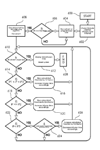
FIG. 7 depicts a process-flow diagram of a safety algorithm implemented during
an infusion
using an exemplary brewing apparatus that includes a SFMS, a brew chamber, an
infusion
pressure sensor, a solvent heater or STMS, and computer control system. The
control system
is preferably configured so the user may specify the brew temperature, initial
brew chamber
fill pressure, brew chamber fill rate, total infusion time and total infusion
volume. The user
may also specify a flow-rate profile or algorithm and, if applicable, input an
algorithm
modification parameter. The process begins at step 600 and immediately
proceeds to step
602, with the user selecting or entering the aforementioned parameters
required to complete a
31
CA 03048629 2019-06-26
WO 2017/189628 PCT/US2017/029488
brew foimula, the computer control system using the temperature setting to
modify the heater
or STMS to heat the solvent to the desired temperature. After the grinds have
been inserted
in the brew chamber the user initiates the infusion cycle.
After the infusion process has been initiated, step 604 includes the control
system initiating a
time counter, a dispensed fluid time counter, and the SFMS to flow fluid at a
user-specified
brew chamber fill rate. Next, step 606 includes the control system checking
the actual
infusion pressure, IP, against the user-specified initial brew chamber fill
pressure using, for
example, one or more sensors associated with the brewing chamber. Once the
initial brew
chamber fill pressure has been reached, i.e., the actual infusion pressure
being greater than or
equal to the fill pressure, step 608 includes the control system recording the
time and volume
of fluid taken to pressurize the brew chamber to the fill pressure. The
control system then
subtracts the time required to fill the brew chamber from the total infusion
time yielding the
remaining infusion time. Likewise, the controller subtracts the volume of
fluid required to
achieve the brew chamber fill pressure from the total fluid volume yielding
the remaining
infusion volume. The control system then uses this data along with the user-
specified flow
rate algorithm and algorithm modification parameter to generate the flow
rate(s) for the rest
of the infusion and immediately flows solvent in accordance with the flow
rate(s) calculated
or generated by the algorithm. An alternate method could be used to sense the
brew chamber
is filled. In this method, solvent is supplied to the brew chamber with a
constant pumping
force, rather than a user specified fill rate, and the control system detects
the brew chamber is
filled by sensing flow rate variance which occurs once the brew chamber is
filled.
While flowing solvent, step 610 includes checking to see if all the desired
dispensed infused
fluid has been dispensed. If all of the infused fluid has been dispensed, step
612 includes the
control system resetting or placing the beverage brewing assembly to a standby
state in
preparation for the next infusion. If all the desired dispensed infused fluid
has not been
32
CA 03048629 2019-06-26
WO 2017/189628 PCT/US2017/029488
dispensed, a safety algorithm monitors pressure within the brew chamber, as
depicted in FIG.
7 in steps 614 through 626
Specifically, step 614 includes comparing the infusion pressure, IP, against a
first safety
pressure, PI, and second safety pressure EN, where EN > IP" If the infusion
pressure, IP,
increases to a point where it is greater than IPi and less than IP2 (//31 < IP
< IP2), step 616
includes decreasing the algorithmically generated flow rate by a first factor
or percentage and
the time of the dispensed volume of infused fluid shot is increased
accordingly, whereby the
total desired shot volume is maintained If infusion pressure, IP, is not
within a value greater
than IP' and less than IP2, step 618 includes comparing the infusion pressure,
IF, against the
second safety pressure IP2. If IP > IP2 , then step 620 includes decreasing
the initial
calculated flow rate by a second factor or percentage, with the shot time
increased
accordingly and whereby the total desired dispensed shot volume is maintained.
If IP is not
equal to or above 1P2, then step 622 includes comparing the infusion pressure,
IF, to a third
pressure, I135. IP3 is preferably lower than IP] and IP2. If IF < IP3 then
step 624 occurs. Step
624 includes comparing the actual volume dispensed to the algorithmically
calculated
volume. If the actual volume is less than the algorithmically generated
volume, then step 626
includes increasing the flow rate by a third factor or percentage, and the
shot time is
decreased accordingly to maintain the desired total volume of dispensed
infused fluid. Steps
610 through 626 are repeated until all the desired fluid is dispensed. The
process may
terminate at step 628 and the steps recited above, unless otherwise expressly
stated, may be
performed in various orders and at different times.
Preferably, the control system conveys the time required to achieve the
specified fill pressure
to the user along with the actual time of the infusion and a graph of the brew
chamber
pressure with respect to time. The control system may store this graph of
infusion pressure
against infusion time for recall, analysis and/or use as a source of
comparison for future
33
CA 03048629 2019-06-26
WO 2017/189628 PCT/US2017/029488
infusions which use that same infusion formula or solute, such that subsequent
infusions may
be optimized through solvent modification to generate a consistent infusion
pressure
In an additional method of operation, scales may be utilized in conjunction
with the
previously described algorithmic brewing control system to provide additional
functionality
to the beverage brewing system. In one embodiment, a scale may be used to
weigh the
dispensed infused solution during the brewing process whereby the control
system is
configured to achieve a desired dispensed infused solution mass. The desired
dispensed
infused solution mass may be directly imputed by the user or calculated by the
control system
from a desired ratio of solute to solution ratio and an inputted solute mass.
The solute mass
may be inputted manually by a user or automatically from a scale.
When used in conjunction with the brew algorithm disclosed in FIG 7, the
variable of, total
dispensed volume, is replaced by a desired dispensed infused solution mass or
a ratio of
solute to dispensed infused solution mass and the mass of the solute. Upon
initiation of the
brew cycle, the control system dispenses fluid at the initial fill rate until
the fill pressure is
achieved. The control system then uses the, dispensed infused solution mass
as the
remaining fluid to dispense and calculates the remaining flow rates based on
this volume and
the time remaining after the fill pressure has been reached. After a portion
of the remaining
time has transpired, the dispensed infused solution mass is compared to the
calculated volume
which should be dispensed at that time. If it is found to be different, the
control system
recalculates the remaining volume to be dispensed and continues the infusion
with the
corrected flowrates. This correction may occur multiple times during an
extraction or a
single time An offset value may also be included to take into account dripping
which may
occur after the infusion has been stopped. This offset value would add or
remove a volume
of fluid from the remaining desired infused solution mass such that the target
infused solution
may be accurately achieved.
34
CA 03048629 2019-06-26
WO 2017/189628 PCT/US2017/029488
Benefits of the aforementioned system may be derived from inclusion of less
than all three
solution control systems: SFMS, STMS and SPMS. For instance, a beverage
brewing
system may include a STMS and SFMS or an alternate configuration may include a
SFMS
and SPMS operably connected to a brewing chamber.
While the disclosed beverage brewing/infusion system mitigates the impact
effect variances
in solute size and solute compaction have on the infusion flavor, it may be
found useful to
utilize data recorded by the control system to modify solute parameters such
as solute size or
solute compaction. The may be accomplished through a solute modification
system, which
may include a solute grinder and/or compaction tool operably connected with
the brewing
chamber where the solute is disposed. In one exemplary system, a control
system, as
described above, is communicatively coupled to a solute modification system,
specifically a
solute grinder, whereby sensor data from an infusion process may be utilized
to modify
performance of said grinder to improve the perfoimance of the total system.
One such
example is utilizing pressure sensor data during an infusion process to modify
the
performance of a grinder to produce smaller or larger solute in order to
ensure a consistent
beverage flavor. For instance, if a beverage is brewed/infused utilizing a
formula and the
SPMS AO, 240, 340 is unable to produce the pressure profile specified by the
formula or
SPMS requires excessive or inordinate levels of flow modulation, the control
system may
communicate with a solute grinder causing it to reduce or increase or decrease
the size of
solute disposed within the brew chamber. As will be obvious, assuming the same
level of
solute compaction and solute mass, a decrease in average solute particle size
will result in
higher solute resistance and an increase in average solute particle size will
result in decreased
resistance enabling lower infusion pressures. Likewise, the system may be
configured to
utilize control system data to modify solute compaction rather than average
solute particle
size.