Note: Descriptions are shown in the official language in which they were submitted.
IS18.0409
PATENT APPLICATION
TOOL POSITION DETECTION SYSTEM
CROSS-REFERENCE TO RELATED APPLICATION
[0001] The present document is based on and claims priority to US
Provisional
Application Serial No.: 62/694,887, filed July 6, 2018, which is incorporated
herein by
reference in its entirety.
BACKGROUND
[0002] To meet consumer and industrial demand for natural resources,
companies
often invest substantial amounts of time and money in searching for and
extracting oil,
natural gas, and other subterranean resources from the earth. Once a desired
subterranean
resource is discovered, drilling and production systems are employed to access
and
extract the resource. These systems may be located onshore or offshore
depending on the
location of a desired resource. Such systems generally include a wellhead
assembly
through which the resource is extracted. These wellhead assemblies may include
a wide
variety of components, e.g. casings, valves, fluid conduits, that control
drilling or
extraction operations. Additionally, such wellhead assemblies may use a
fracturing tree
and other components to facilitate a fracturing process and to enhance
production from a
well. As will be appreciated, resources such as oil and natural gas are
generally extracted
from fissures or other cavities formed in various subterranean rock formations
or strata.
[0003] To facilitate extraction of such resources, a well may be
subjected to a
fracturing process that creates one or more fractures in a rock formation.
These fractures
may connect to pre-existing fissures and cavities enabling oil and gas to flow
into the
wellbore. The fracturing process may include perforating the rock formation
with
1
Schlumberger-Private
CA 3048717 2019-07-05
=
IS18.0409
charges and then injecting a pressurized fracturing fluid into the well. The
high pressure
of the fluid increases crack size and crack propagation through the rock
formation to
release oil and gas, while the proppant prevents the cracks from closing once
the fluid is
depressurized. To create the perforations, a tool lowers the charges to a
desired well
depth. After perforating the rock formation with the charges, the tool is
removed from
the well and the well is pressurized to increase crack propagation. However,
closing one
or more valves before removing the tool from the well may sever the wireline
suspending
the tool.
[0004] Attempts have been made to track tool position so as to
prevent premature
closing of the valve(s). For example, wireline tools strings may be deployed
and
retrieved as the wireline passes through reels. Such reels have been equipped
with
optical encoders which can be used to track movement of the wireline.
Additionally,
sensors have been used to scan for objects along the tool string to determine
position.
However, such approaches can be highly dependent on the hardware/software
implementation or sensing accuracy which can substantially increase
operational cost.
SUMMARY
[0005] In general, a system and methodology are provided for
operation at a
wellhead to facilitate use of tools downhole. According to an embodiment, a
frac stack
may be coupled to the wellhead and may include a flow control device which
opens and
closes a bore extending through the wellhead. A lubricator may be coupled to
the frac
stack. The lubricator includes a tool trap which opens and closes to
facilitate controlled
movement of a tool along the bore. A tool position detection system is used to
detect a
position of the tool in the tool trap to ensure, for example, removal of the
tool from the
frac stack before closure of the flow control device.
[0006] However, many modifications are possible without
materially departing
from the teachings of this disclosure. Accordingly, such modifications are
intended to be
included within the scope of this disclosure as defined in the claims.
2
Schlumberger-Private
CA 3048717 2019-07-05
IS18.0409
BRIEF DESCRIPTION OF THE DRAWINGS
[0007] Certain embodiments of the disclosure will hereafter be
described with
reference to the accompanying drawings, wherein like reference numerals denote
like
elements. It should be understood, however, that the accompanying figures
illustrate the
various implementations described herein and are not meant to limit the scope
of various
technologies described herein, and:
[0008] Figure 1 is a schematic illustration of a well system which
may be used for
performance of a hydraulic fracturing operation, according to an embodiment of
the
disclosure;
[0009] Figure 2 is a schematic illustration of another example of a
well system
which may be used for performance of a hydraulic fracturing operation,
according to an
embodiment of the disclosure;
[0010] Figure 3 is a schematic illustration of an example of a
fracturing tree,
according to an embodiment of the disclosure;
[0011] Figure 4 is a schematic cross-sectional illustration of an
example of a
lubricator with a tool trap, according to an embodiment of the disclosure;
[0012] Figure 5 is a schematic cross-sectional illustration of an
example of a
lubricator with a tool being moved up into the tool trap, according to an
embodiment of
the disclosure;
[0013] Figure 6 is a schematic cross-sectional illustration of an
example of a
lubricator with a tool being moved through a flapper positioned within the
tool trap,
according to an embodiment of the disclosure;
3
Schlumberger-Private
CA 3048717 2019-07-05
IS18.0409
[0014] Figure 7 is a schematic cross-sectional illustration of an
example of a
lubricator with a tool being moved up out of the tool trap, according to an
embodiment of
the disclosure;
[0015] Figure 8 is a graphical illustration showing angular
displacement over time
with respect to a flapper of a tool trap as a tool passes through the tool
trap, according to
an embodiment of the disclosure;
[0016] Figure 9 is a graphical illustration showing details of
movement of a tool
trap external handle as a flapper is pivoted between positions, according to
an
embodiment of the disclosure;
[0017] Figure 10 is a schematic cross-sectional illustration of an
example of a
lubricator with a tool position detection system, according to an embodiment
of the
disclosure;
[0018] Figure 11 is a schematic cross-sectional illustration of
another example of
a lubricator with a tool position detection system, according to an embodiment
of the
disclosure;
[0019] Figure 12 is a schematic cross-sectional illustration of
another example of
a lubricator with a tool position detection system, according to an embodiment
of the
disclosure;
[0020] Figure 13 is a schematic cross-sectional illustration of
another example of
a lubricator with a tool position detection system, according to an embodiment
of the
disclosure; and
[0021] Figure 14 is a schematic cross-sectional illustration of
another example of
a lubricator with a tool position detection system, according to an embodiment
of the
disclosure.
4
Schlumberger-Private
CA 3048717 2019-07-05
IS18.0409
DETAILED DESCRIPTION
[0022] In the following description, numerous details are set forth
to provide an
understanding of some embodiments of the present disclosure. However, it will
be
understood by those of ordinary skill in the art that the system and/or
methodology may
be practiced without these details and that numerous variations or
modifications from the
described embodiments may be possible.
[0023] The disclosure herein generally involves a system and
methodology to
facilitate well operations involving tools which are employed downhole in a
borehole,
e.g. a wellbore. According to an embodiment, a frac stack may be coupled to a
wellhead
and may include a flow control device, e.g. a valve, which opens and closes a
bore
extending through the wellhead. A lubricator may be coupled to the frac stack.
The
lubricator includes a tool trap which opens and closes to facilitate movement
of a tool
along the bore, e.g. deployment of the tool downhole or retrieval of the tool.
[0024] By way of example, a tool may be deployed or retrieved via
wireline.
During deployment, the tool is placed inside the tool trap of the lubricator,
which may
have a grease-injection section and sealing elements. After the lubricator is
pressurized
to wellbore pressure, top valves (or other type of flow control device) of a
frac tree may
be opened to enable the tool to fall into or be pumped into the wellbore.
After the
wireline operation is completed, the reverse process is used and the tool is
pulled up into
the tool trap of the lubricator under wellbore pressure. The frac tree valves
are than
closed and pressure in the lubricator is bled off. The lubricator may then be
opened for
removal of the tool. In various applications, the frac tree uses gate valves
or other
suitable valves which, if closed prematurely, can cut the wireline cable. This
can lead to
undesirable events such as the tool falling back into the well. However, a
tool position
detection system described herein prevents premature closing of the valves,
e.g. gate
valves, and thus prevents undesirable cutting of the wireline cable.
Schlumberger-Private
CA 3048717 2019-07-05
. ,
IS18.0409
[0025] The tool may comprise a variety of tools and tool
strings. In some
embodiments, the tool may comprise an individual tool or a string of tools,
e.g. a
perforating gun, a logging tool, or another type of tool, conveyed downhole
for
performance of a desired well operation. The tool, e.g. tool string, is then
retrieved to the
surface before subsequent well operations are performed. The tool position
detection
system is used to detect a position of the tool in the tool trap to ensure,
for example,
removal of the tool from the frac stack before closure of the flow control
device, e.g.
closure of a valve or valves.
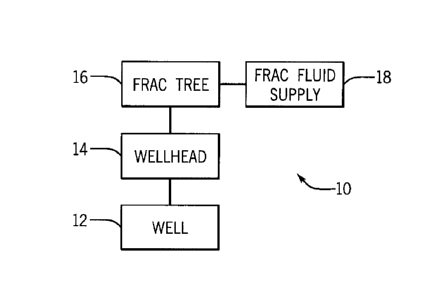
[0026] Referring generally to Figures 1 and 2, examples
of a fracturing system,
e.g. a hydraulic fracturing system, 10 are provided in accordance with certain
embodiments. The fracturing system 10 facilitates extraction of natural
resources, such
as oil or natural gas, from a subterranean formation via one or more wells 12
and
wellheads 14. By injecting a pressurized fracturing fluid into a well 12, the
fracturing
system 10 increases the number and/or size of fractures in a rock formation or
strata to
enhance recovery of natural resources. The illustrated wells 12 are surface
wells, but it
will be appreciated that resources may be extracted from other types of wells
12, such as
platform or subsea wells.
[0027] The fracturing system 10 may include various
components to control flow
of a fracturing fluid into the well 12. For example, the fracturing system 10
depicted in
Figure 1 includes a fracturing tree 16 which receives fracturing fluid from a
fluid supply
18. In some embodiments, the fracturing fluid supply 18 is provided by trucks
that pump
the fluid to fracturing tree 16, however other suitable sources of fracturing
fluid and
techniques for transmitting such fluid to the fracturing trees 16 may be used.
The fluid
supply 18 may be connected to fracturing tree 16 directly or via a fracturing
manifold 22,
as generally illustrated in Figure 2. The fracturing manifold 22 may include
conduits,
e.g. pipes, as well as valves or sealing rams to control the flow of
fracturing fluid to the
fracturing trees 16 (or from the fracturing trees 16 during, for example, a
flow back
operation). As illustrated in Figure 2, the fracturing manifold 22 provides
fracturing fluid
6
Schlumberger-Private
CA 3048717 2019-07-05
IS18.0409
to multiple fracturing trees 16 and this fracturing fluid may then be routed
into respective
wells 12 via corresponding wellheads 14. In some embodiments, the fracturing
manifold
22 may be coupled to a single fracturing tree 16.
[0028] An example of a fracturing tree 16 is illustrated in Figure
3. The
fracturing tree 16 includes a goat head 26, wing valves 28 and 30, and a frac
stack 32.
The goat head 26 includes one or more connections for coupling the fracturing
tree 16 to
the fluid supply 18, e.g. via fracturing manifold 22. This allows fracturing
fluid from the
fluid supply 18 to enter the fracturing tree 16 through the goat head 26 and
to then flow
into the frac stack 32. When included, the wing valves 28, 30 may have various
forms.
In some embodiments, the wing valves 28 include pump down valves for
controlling the
flow of a pump down fluid into the frac stack 32, while the wing valves 30 may
include
valves for controlling flow back fluid exiting the well 12 through the
wellhead 14 and the
frac stack 32.
[0029] The frac stack 32 may include a flow control device 34, e.g.
valve(s) or
ram(s). The flow control device 34 may comprise at least one valve and/or at
least one
ram which may be used to control flow of the fracturing fluid with respect to
the
fracturing tree 16, e.g. into or out of well 12. The valve system of frac
stack 32 also may
include actuators 36 which correspond with the valves/rams 34. By way of
example,
each actuator 36 may be an electric actuator, pneumatic actuator, hydraulic
actuator,
other suitable type of actuator, or a combination thereof.
[0030] To facilitate insertion of tools into the well 12, the
fracturing tree 16
includes a lubricator 38 coupled to the frac stack 32 via, for example, goat
head 26. The
lubricator 38 is an assembly with a conduit that enables a tool, e.g. a tool
string, to be
inserted into the well 12 under pressure. The tool string may include logging
tools,
perforating guns, and/or other types of tools. For example, a perforating gun
may be
placed in the lubricator 38 for insertion into the well 12. The pressure in
the lubricator
may then be increased until it reaches the pressure of the well 12. The frac
stack 32 is
then opened enabling the perforating gun to be lowered into the well 12 with a
wireline.
7
Schlumberger-Private
CA 3048717 2019-07-05
IS 18.0409
After performing downhole operations, e.g. perforating the casing, the
tool/perforating
gun is withdrawn back into the lubricator with the wireline. The lubricator 38
may then
be depressurized and the perforating gun removed (or the perforating gun may
be left in
the lubricator 38 until it is used again). After retrieving the tool to the
lubricator 38, the
flow control device 34, e.g. one or more valves, in the frac stack 32 may
again be closed.
However, closing the flow control device 34 in the frac stack 32 before
completely
withdrawing the tool may sever the wireline suspending the tool. The
fracturing system
therefore includes a tool position detection system 40 to detect withdrawal of
the tool
out of the frac stack 32. The tool position detection system 40 may be used to
increase an
operator's situational awareness on a jobsite when controlling valves in the
fracturing
system 10.
100311 Referring generally to Figure 4, a cross-sectional view is
provided of an
embodiment of the lubricator 38 with a tool trap 60. As explained above, the
lubricator
38 is an assembly that facilitates the insertion of tools into a well 12. The
lubricator 38
includes a conduit 62 capable of containing high pressures in situations where
the
lubricator 38 is pressurized. For example, the conduit 62 may be pressurized
to facilitate
tool transmission into well 12 by equalizing the pressure in the lubricator 38
with the
pressure of the well 12. The conduit 62 defines a bore 64 through which tools
pass into
and out of the well 12. To block unintended insertion of tools into the well
12, the
lubricator 38 may include the tool trap 60. In the example illustrated, the
tool trap 60
includes a flapper 66, e.g. a projection or plate, placed within the bore 64.
The flapper 66
is coupled with a shaft 68 that passes through an aperture 70 which may be
oriented
generally transversely with respect to the conduit 62 as illustrated. Rotation
of the shaft
68 opens the flapper 66 to enable tools to pass through the lubricator 38 and
into the well
12. The shaft 68 may be coupled to an actuator 72 which enables rotation of
the flapper
66 from a closed position, i.e. when the flapper extends across the bore 64,
to an open
position. In some embodiments, the actuator 72 may include or may be in the
form of a
manual actuator having an external handle 74. However, the actuator 72 may be
an
electric actuator, pneumatic actuator, hydraulic actuator, or an actuator
having a
combination of actuating mechanisms.
8
Schlumberger-Private
CA 3048717 2019-07-05
IS18.0409
[0032] Wirelines may be coupled with tools to lower them into well
12 and to
enable retrieval of the tools. To facilitate movement of the tool into and out
of the well
12 and through the tool trap 60, the flapper 66 may define a slot or aperture
76. The slot
or aperture 76 enables a wireline, while coupled to the tool, to pass through
the flapper 66
when the flapper 66 is in a closed position, i.e. when the flapper extends
across the bore
64.
[0033] Referring generally to Figure 5, a cross-sectional
illustration is provided of
lubricator 38 with a tool 100 positioned below tool position detection system
40. As
explained above, tool 100 may comprise various tools such as logging tools
and/or
perforating guns and may be inserted into well 12 to perform various downhole
operations. Such tools 100 may be inserted through the lubricator 38 which may
be used
to equalize pressure of fluid surrounding the tool 100 with the pressure of
fluid in the
well 12 to facilitate insertion of the tool 100 into the well 12. To prevent
premature or
unintended insertion of tool 100 into well 12, the lubricator 38 includes tool
trap 60. The
tool trap 60 comprises flapper 66 which rests within the bore 64 and blocks
movement of
tool 100 in direction 102 without input from actuator 72. That is, the flapper
66 is unable
to rotate in direction 104, e.g. counterclockwise in the embodiment
illustrated in the
Figure, from a set position or closed position. Accordingly, objects moving in
direction
102 are unable to freely pass through the tool trap 60 without an actuator
rotating the
flapper 66 in direction 106 and out of the way of tool 100. However, because
the flapper
66 freely rotates in direction 106, tools 100 that are axially below the
flapper 66 are able
to move in direction 108. As the tool 100 moves in direction 108, the tool 100
contacts
the flapper 66 and the flapper is rotated in direction 106. The tool 100 is
then able to
slide past the flapper 66 and through the tool trap 60. After the tool 100
passes through
the tool trap 60, the flapper 66 rotates in direction 104 to the closed
position illustrated in
Figure 5, thus blocking the tool from entering the well 12.
[0034] As explained above, the frac stack 32 may include flow
control device 34,
e.g. one or more valves. Closing the flow control device 34 before completely
9
Schlumberger-Private
CA 3048717 2019-07-05
IS18.0409
withdrawing the tool 100 may sever a wireline 110 used to suspend the tool 100
within
the well 12. To detect whether the tool 100 has been sufficiently retracted,
e.g.
completely pulled into the lubricator 38, the fracturing system 10 includes
the tool
position detection system 40. The tool position detection system 40 provides
feedback to
increase situational awareness of the location of the tool 100. In some
embodiments, the
tool position detection system 40 is coupled with the tool trap 60 to
determine the
location of tool 100. For example, the tool position detection system 40 may
be used to
determine whether the tool 100 is above or below the flapper 66 and therefore
whether
the tool 100 is completely within the lubricator 38 and/or whether the
wireline 110 or tool
100 is within the frac stack 32.
[0035] According to an embodiment, the tool position detection
system 40
comprises one or more sensors 112, e.g. positional sensors or angular sensors.
The
sensors 112 may be coupled to the shaft 68 to detect rotation of the shaft 68.
It should be
noted the sensor 112 (or sensors 112) also may be mounted so as to detect
movement of
external handle 74 (see Figure 4). The sensors 112 send signals to a
controller 114 so as
to indicate, for example, rotation of the shaft 68. In response, the
controller 114 uses one
or more processors 116 to execute instructions stored on one or more memories
118 to
track the changes in position of the shaft 68 (and/or handle 74) with respect
to time. As
explained in greater detail below, by tracking the change in position with
respect to time,
the controller 114 is able to determine if the tool 100 has passed through the
tool trap 60
and whether it is fully within the lubricator 38, i.e. axially above the
flapper 66 in the
lubricator 38.
[0036] By way of example, the processor 116 may be a microprocessor
which
executes software. The processor 116 may include multiple microprocessors, one
or
more general-purpose microprocessors, one or more special-purpose
microprocessors,
and/or one or more application-specific integrated circuits (ASICS), or some
combination
thereof. For example, the processor 116 may include one or more reduced
instruction set
(RISC) processors.
Schlumberger-Private
CA 3048717 2019-07-05
IS18.0409
[0037] The memory 118 may include a volatile memory, such as random-
access
memory (RAM), and/or a nonvolatile memory, such as read-only memory (ROM). The
memory 118 may store a variety of information and may be used for various
purposes.
For example, the memory 118 may store processor executable instructions, such
as
firmware or software, for the processor 116 to execute. The memory may include
ROM,
flash memory, a hard drive, or other suitable optical, magnetic, or solid-
state storage
medium, or a combination thereof. The memory may store data, instructions, and
other
suitable data.
[0038] Figure 6 provides a cross-sectional view of the lubricator 38
with the tool
100 passing through tool position detection system 40. As the wireline 110
retracts and
withdraws the tool 100 from the well 12, the wireline 110 passes freely
through the
aperture or opening 76 in the flapper 66. However, the tool 100 is too large
to pass
through the aperture/opening 76 in flapper 66. A top surface of the tool 100
therefore
contacts a bottom surface 132 of the flapper 66. The force of the tool 100 on
the flapper
66 rotates the flapper in direction 106 while also rotating shaft 68 (and
external handle 74
if such handle is included. The sensor 112 detects rotation of the shaft
68/movement of
handle 74 and communicates this movement to the controller 114.
[0039] Figure 7 provides a cross-sectional view of the lubricator 38
with the tool
100 after the tool 100 has passed through the tool trap 60. After the tool 100
passes
through the tool trap 60, the flapper 66 no longer contacts the tool 100 which
allows
gravity to return the flapper 66 to the closed position by rotating the
flapper 66 in
direction 104. In this position, the flapper 66 is able to block tools 100
from passing
through the lubricator 38 in direction 102. Rotation of the flapper 66 and the
shaft
68/handle 74 in direction 104 is detected by the sensor 112 and communicated
to the
controller 114.
[0040] As indicated above and as illustrated in Figure 4, one or
more sensors 112
may be mounted on or adjacent the external handle 74 of the tool trap 60. For
example, a
position sensor 112 (or other suitable sensor) may be mounted on or adjacent
the external
11
Schlumberger-Private
CA 3048717 2019-07-05
IS18.0409
handle 74 to monitor the handle angle as the handle 74 rotates during passing
of the tool
100. The movement of handle 74 may be monitored and recorded in real-time. By
way
of example, the angle/position of the handle 74 may be monitored and
explicitly
displayed on, for example, a computer display by virtue of suitable operation
software
such as FracTree operation software. As a result, an operator can view and
monitor the
physical movement of the handle 74. The monitoring data also may be recorded
so that
passing of the tool 100 may be captured and reported even if the actual event
is not
viewed.
[0041] Referring generally to Figure 8, a graph 150 is provided to
illustrate the
angular displacement of the flapper 66 with respect to time as the tool 100
passes through
the tool trap 60. As illustrated, the y-axis 152 represents the change in
angle of the
flapper 66 and the x-axis represents time. The line 156 represents feedback
from the
sensor 112 as the sensor 112 detects changes in position over time as tool 100
contacts
the flapper 66 and moves through the tool trap 60. By way of example, this
movement
may be monitored by using sensor 112 to monitor rotation of shaft 68 and/or
movement
of external handle 74. In the illustrated example, the graph line 156
represents three
phases 158, 160 and 162 of the tool 100 passing through the tool trap 60. In
the first
phase 158, the graph line 156 represents the tool 100 contacting and rotating
the flapper
66 out-of-the-way of tool 100. In the second phase 160, the graph line 156
represents the
tool 100 sliding past the flapper 66 in an open position. In the third phase
162, the graph
line 156 represents the tool 100 having passed completely through the tool
trap 60 and
the flapper 66 rotating back to a closed position.
[0042] The data obtained from the sensor or sensors 112 may be
collected and
stored over time. In Figure 9, for example, a graph is provided which
indicates the
instantaneous and historical position of external handle 74 when monitored by
a
corresponding sensor or sensors 112. The recorded data provides a "signature"
of the
movement of external handle 74. This graph provides details of angle change of
the
external handle in the period starting from an end of a stage to the beginning
of the next
stage. In various applications, the flapper 66 may be held at a vertical open
position most
12
Schlumberger-Private
CA 3048717 2019-07-05
IS18.0409
of the time during a stage to reduce wear on the wireline/cable 110 due to
possible
abrasion as it moves through the slot or aperture 76. When the tool 100
approaches the
ground surface, e.g. a few hundred feet from the ground, actuation force (e.g.
hydraulic
force) applied to the external handle 74 is released. This allows the handle
74 and the
flapper 66 to return to the horizontal, closed position which also allows the
corresponding
sensor 112 to provide data regarding the passing of tool 100. This transition
is marked as
time period 1 in Figure 9.
[0043] When the tool 100 arrives and pushes the flapper 66 open,
this is indicated
at time period 2 as the angle of external handle 74 increases and eventually
returns to 0
when the tool 100 passes. After the tool 100 fully returns to the lubricator
38, the
lubricator 38 may be detached from the frac tree. The tool 100 may then be
taken out of
the lubricator 38 for the preparation of the next stage's perforation. In this
example, the
tool trap flapper 66 opens in one direction and the tool 100 cannot exit the
lubricator 38
from the top. Therefore, in time period 3, actuation force is applied to the
handle 74 to
let the tool 100 exit at the bottom of the lubricator 38 for reloading.
[0044] After reloading, the tool 100 may be retracted to the
lubricator 38 which
will be attached to the top of the frac tree for the next stage operation.
During time
period 4, the tool trap 60 is closed to prevent the tool 100 from accidentally
falling during
the movement. After the next age operation starts, actuation force is applied
to the
flapper 66 so that it will be held in an upward position once again to reduce
the potential
abrasion to the wireline 110. This action is illustrated in time period 5. The
graphical
example provided in Figure 9 demonstrates that there may be multiple instances
of a
change in angle of the flapper 66 from horizontal to vertical during an
operational event
involving pulling the tool 100 out of the well. The handle 74 and flapper 66
also can
transition for various other reasons. However, various sensor systems may be
used to
accurately track the position of tool 100. For example, a backup sensor
system, e.g. one
or more backup sensors, may be used to ensure accurate detection and knowledge
with
respect to the position of both flapper 66 and tool 100 as described in
greater detail
below.
13
Schlumberger-Private
CA 3048717 2019-07-05
IS18.0409
[0045] Referring generally to Figure 10, a cross-sectional view is
provided of
lubricator 38 with tool position detection system 40. The tool position
detection system
40 includes first and second sensors 170, 172 which enable the controller 114
to
determine the position of flapper 66. More specifically, the first and second
sensors 170,
172 enable the controller to determine if the flapper is in an open position
or a closed
position. The first sensor 170 rests on a side 174 of the conduit 62 opposite
a side 176
which is coupled to the shaft 68. This arrangement enables the sensor 170 to
detect when
the flapper 66 is in a closed position. For example, the flapper 66 may
include a magnet
178 in an end 180 of the flapper 66. The sensor 170 detects the presence of
the magnet
178 and transmits the signal to the controller 114. The controller 114 is thus
able to
determine that the flapper 66 is in a closed position. The sensor 170 also
transmits to the
controller 114 a signal indicating the absence of the magnet 178 which may
indicate that
the flapper is in an open position. As explained above, when the tool 100
passes through
the tool trap 60, the flapper 66 rotates in direction 106 in response to
contact between the
tool 100 and the flapper 66. As the flapper 66 and magnet 178 rotate away from
the
sensor 170, the sensor 170 detects the absence of the magnet 178.
[0046] In some embodiments, the tool position detection system 40
may include
the second sensor 172 to detect whether the flapper 66 transitions from a
closed position
to an open position. For example, the wireline 110 may catch on the flapper 66
or
vibrations in the fracturing system 10 may move the flapper 66. These
movements may
be detected by the sensor 170 and interpreted as an opening of the flapper 66.
By
including the second sensor 172, the tool position detection system 40 is able
to detect
whether the flapper 66 has opened sufficiently for the tool 100 to pass
through the tool
trap 60. The sensor 172 likewise detects the presence of the flapper 66 and/or
the
presence of the magnet 178 coupled to the flapper 66. In this way, the
controller 114
may receive multiple signals indicating the position of flapper 66. By
monitoring the
signals over time, the controller 114 is able to determine when the flapper is
transitioned
from a closed position to an open position and then back to a closed position,
thus
accurately determining whether the tool 100 is within the lubricator 38. It
should be
14
Schlumberger-Private
CA 3048717 2019-07-05
IS18.0409
noted sensors 170, 172 may be combined with sensors 112 to provide multiple
indications of flapper movement.
[0047] Referring generally to Figure 11, a cross-sectional view is
provided of
lubricator 38 with tool position detection system 40. In some embodiments, the
tool
position detection system 40 may include at least one sensor, e.g. sensors
202, 204, to
directly detect the position of tool 100. The sensors 202, 204 may be used
alone or as a
backup sensor system to the flapper movement detection sensors, e.g. sensors
112, 170,
172. In some embodiments, the at least one sensor 202, 204 is designed to
detect at least
one magnet 200 which may be coupled with the tool 100. For example, the at
least one
magnet 200 may be constructed as a casing collar locator (CCL). A casing
collar locator
uses magnets to detect casing collars that couple casing joints together as it
descends or
ascends so as to calculate a distance the tool 100 has traveled within the
well 12.
[0048] By way of example, a pair of magnetic sensors, e.g. sensors
202, 204, may
be used to detect a signal difference over time based on the presence of
magnet 200. By
detecting the magnet 200 coupled to the tool 100, the tool position detection
system 40 is
able to determine whether the tool 100 is within the lubricator 38. The
indications from
sensors 202, 204 may be used in combination with the data provided by the
flapper
rotation sensors, e.g. sensors 112, 170, 172. In this manner, sensors 202, 204
may be
used as a backup system to ensure an accurate determination of the position of
tool 100
with respect to tool trap 60.
[0049] It should be understood that sensors 202, 204 may be placed
farther away
from the tool trap 60 to ensure the entire tool 100 is above the flapper 66
when moving in
direction 108. The tool position detection system 40 may include first and
second
sensors 202 and 204 to provide redundancy as well as to enable the controller
114 to
determine the direction of travel of the tool 100. Determining the direction
of travel
enables the controller 114 to determine if the tool 100 is moving into
lubricator 38 from
below or heading into the well 12. For example, if the tool 100 is moving in
direction
108, the sensor 204 detects the magnet 200 first followed by the sensor 202.
Detection of
Schlumberger-Private
CA 3048717 2019-07-05
IS18.0409
the magnet 200 in this time order indicates the tool 100 is moving into or is
within the
lubricator 38. Likewise, if the tool 100 is moving in direction 102, the
sensor 202 will
first detect the magnet 200 followed by the sensor 204. A detection of the
magnet 200 in
this time order indicates that the tool is still in the well 12 or moving into
the well 12. In
this manner, the order of detection in combination with the time-lapse enables
a
controller 114 to determine the direction of travel of the tool and therefore
whether the
tool 100 is within the lubricator 38 or in the well 12. As described above,
this data may
be combined with data from the flapper position sensors, e.g. sensors 112,
170, 172, to
further verify the position of tool 100, e.g. to verify whether the tool 100
is within
lubricator 38.
[0050] Referring generally to Figure 12, a cross-sectional
illustration is provided
of lubricator 38 with tool position detection system 40. In this type of
embodiment, the
tool position detection system 40 may comprise sensors, such as sensors 220,
222 which
directly detect the presence of tool 100 rather than rotation of flapper 66.
These types of
sensors 220, 222 may be used alone to detect the position of tool 100 or as a
backup
system to the flapper position sensors, e.g. sensors 112, 170, 172. In this
example,
sensors 220 and 222 may be selected to detect ultrasonic signals emitted from
respective
emitters 224 and 226 (e.g. ultrasonic emitters). As the tool 100 passes
between emitters
224, 226 and sensors 220, 222, the tool 100 changes the signals, e.g. distorts
the signals,
from emitters 224, 226. The sensors 220, 222 detect the changes, e.g.
distortions, of the
ultrasonic signals and transmit this to the controller 114. The controller 114
interprets
this change/distortion as indicative of the presence of tool 100 and thus
whether the tool
100 is within lubricator 38. It should be understood that sensors 220, 222 and
emitters
224, 226 may be placed farther away from the tool trap 62 ensure the entire
tool 100 is
above the flapper 66 when moving in direction 108.
[0051] The tool position detection system 40 may include first and
second sensors
220 and 222 to provide redundant detection as well as to enable the controller
114 to
determine the direction of travel of tool 100. Determining the direction of
travel enables
the controller 114 to determine if the tool 100 has been retracted into
lubricator 38 or is
16
Schlumberger-Private
CA 3048717 2019-07-05
IS18.0409
heading into well 12. For example, if the tool is moving in direction 108, the
sensor 222
first detects the tool 100 followed by the sensor 220. A detection of the tool
100 in this
time order indicates the tool 100 is moving into or is within the lubricator
38. Likewise,
if the tool 100 is moving in direction 102, the sensor 220 detects the tool
100 first
followed by the sensor 222. A detection of the tool 100 in this time order
indicates that
tool 100 is still in the well 12 or descending into the well 12. In this
manner, the order of
detection in combination with the time-lapse enables a controller 114 to
determine the
direction of travel of the tool and therefore whether the tool 100 is within
the lubricator
38 or in the well 12. As described above, this data may be combined with data
from the
flapper position sensors, e.g. sensors 112, 170, 172, to further verify the
position of tool
100, e.g. to verify whether the tool 100 is within lubricator 38.
100521 It should be noted that an additional sensor or sensors may
be used to
determine the state of the valve/ram 34. This knowledge could help reduce
false
reporting. The data from the flapper position provided by flapper position
sensors, e.g.
sensors 112, 170, 172, may be used in combination with tool position sensor
data from,
for example, sensors 202, 204, 220, 222, 228, 230 to enable improved decision-
making
with respect to closing the valve/ram 34 on the path of the wireline tool 100.
However,
this decision-making is needed only when the valve/ram 34 is open. If the
valve/ram 34
is already closed, the decision is not needed.
100531 Referring generally to Figures 13 and 14, another embodiment
is
illustrated in which sensors 228, 230 are placed sufficiently high on the
lubricator 38
such that one or both sensors are able to detect when a collar locator (CCL),
e.g. magnet
200, is sufficiently above the flow control device 34 to enable flow control
device
closure, e.g. valve closure. This type of arrangement eliminates the need for
tool trap 60
although certain embodiments also may employ tool trap 60 in combination with
sensors
228, 230. In the arrangement illustrated in Figure 13, the top sensor 228 is
positioned to
detect when tool 100, e.g. a tool string, is a safe distance from flow control
device 34 to
enable closure. In the arrangement illustrated in Figure 14, the top sensor
228 and the
17
Schlumberger-Private
CA 3048717 2019-07-05
IS18.0409
bottom sensor 230 are both positioned to detect when the tool 100, e.g. a tool
string, is a
safe distance from flow control device 34 to enable closure.
[0054] According to a first scenario, the sensors 228, 230
(illustrated in Figure
13) may work in cooperation with controller 114 to place the system into an
"allow this
valve to be closed" state when the valve 34 initially changes from closed to
open. Upon
detecting movement of the CCL/magnets 200 past either sensor 228, 230, the
system
would move to one of two "disallow closing" states. The first state ("disallow
closing,
CCL below top sensor 228") enables the system to return to "allow this valve
to be
closed" or to proceed to "disallow closing, CCL below bottom sensor" depending
on the
next detection. When the next detection is from the lower sensor 230, the
system state
advances to "disallow closing, CCL below bottom sensor 230" which would be the
expected state path. However, in the case of a problem not related to the
system, the
CCL may drop below the top sensor 228 and then return to a position above the
top
sensor 228 in which case the system state should return to "allow this valve
to be closed".
In either case, the system is not allowed to return to the "allow this valve
to be closed"
state after detection from the lower sensor 230 until it detects a movement in
the up
direction.
[0055] In a second scenario where both sensors 228, 230 are
positioned to detect
whether the tool 100, e.g. tool string, is at a safe distance from the flow
control device 34
(see Figure 14), the approach may be similar to that described above with
respect to the
first scenario. However, arming into the "disallow closing" state only happens
when
movement is detected past the bottom sensor 230. The two sensors 228, 230 are
still used
as a state change back to "allow this valve to be closed" and this involves
detection of
CCL 200 past both sensors 228, 230 in the up direction. The software/logic for
both the
first scenario and the second scenario can be implemented on, for example,
controller 114
via software. The logic (state diagram) from the first scenario would work in
the second
scenario. By using the same logic for both scenarios, an operator would not
have to
select one option or the other with respect to the software utilized.
18
Schlumberger-Private
CA 3048717 2019-07-05
IS18.0409
[0056] Such a logic system for utilizing data from sensors 228, 230
could be
embodied in software on controller 114 and would be useful for helping
wireline
companies avoid two common failures associated with wireline pressure
operations and
specifically with pull-offs associated with bumping up the tool 100 upon
return to surface
and failure to bleed off the pressure on the tool trap 60. When retrieving
wireline tools in
wells with pressure, a "bump-up" in the lubricator is desired before closing
the well.
When "bumping up", a wireline operator pushes down on the wireline or lower
sheave.
This creates a longer path in the wireline such that when the tool 100 touches
the top of
the lubricator 38, the operator can feel the bump while the longer path allows
time for the
winch operator to shut down the winch. The sensing and state techniques
described with
respect to Figures 13 and 14 can be used by the wireline crew to shut down the
winch
automatically when the proper state is recognized. This would be especially
beneficial
when the tool 100, e.g. tool string, is heavy and the pushing down on the
wireline cannot
generate much deflection. This approach also can be used in conjunction with a
depth
detection system to remind the operator to bleed off pressure on the tool trap
60.
Accordingly, the various embodiments described herein can be used with a
variety of
tools, techniques, and operational applications.
[0057] Although a few embodiments of the disclosure have been
described in
detail above, those of ordinary skill in the art will readily appreciate that
many
modifications are possible without materially departing from the teachings of
this
disclosure. Accordingly, such modifications are intended to be included within
the scope
of this disclosure as defined in the claims.
19
Schlumberger-Private
CA 3048717 2019-07-05