Note: Descriptions are shown in the official language in which they were submitted.
NON-AXISYMMETRIC IMPELLER HUB FLOWPATH
BACKGROUND
100011 Centrifugal compressors are commonly used for fluid compression in
rotating
machines such as, for example, a gas turbine engine. Gas turbine engines
typically include at
least a compressor section, a combustor section, and a turbine section. In
general, during
operation, air is pressurized in the compressor section and is mixed with fuel
and burned in the
combustor section to generate hot combustion gases. The hot combustion gases
flow through the
turbine section, which extracts energy from the hot combustion gases to power
the compressor
section and other gas turbine engine loads.
100021 A centrifugal compressor is a device in which a rotating rotor or
impeller delivers
air at relatively high velocity by the effect of centrifugal force on the gas
within the impeller.
The impeller typically comprises a plurality of vanes circumferentially spaced
about a hub.
Centrifugal impellers have complex three-dimensional flow structures due to
turning of the flow
in both the tangential and radial dimensions. Improvements to impeller
geometries are desirable
to increase impeller efficiency and uniformity of the gas flow exiting the
impeller.
SUMMARY
100031 According to some aspects of the present disclosure, a centrifugal
impeller
comprises a hub and a plurality of circumferentially spaced vanes. The hub has
a flowpath
surface and an axis of rotation. The plurality of circumferentially spaced
vanes extend from the
flowpath surface, each of the vanes having a pressure-side fillet and a
suction-side fillet
extending from a leading edge to a trailing edge of the vane. Each of the
pressure-side fillet and
RCA12127CA 1
DW12\9935632 1
CA 3049046 2019-07-10
suction-side fillet intersect the flowpath surface at a runout. The runout of
the pressure-side fillet
of a first vane is asymmetric to the runout of the suction-side fillet of the
first vane.
[0004] In some embodiments the runout of the pressure-side fillet of a
first vane is
asymmetric to the runout of the suction-side fillet of an adjacent second
vane. In some
embodiments the runout of the pressure-side fillet of a first vane is
asymmetric to the runout of
the pressure-side fillet of an adjacent second vane. In some embodiments the
runout of the
pressure-side fillet of a first vane is asymmetric to the runout of the
suction-side fillet of an
adjacent second vane.
[0005] In some embodiments the runout of the pressure-side fillet of a
first vane is
asymmetric to the runout of the suction-side fillet of the first vane for a
first portion of the length
of the first vane, and wherein the runout of the pressure-side fillet of a
first vane is symmetric to
the runout of the suction-side fillet of the first vane for a second portion
of the length of the first
vane. In some embodiments the first portion is proximate an impeller
discharge. In some
embodiments a maximum asymmetry between the runout of the pressure-side fillet
and the
runout of the suction-side fillet is proximate the impeller discharge. In some
embodiments a
maximum asymmetry between the runout of the pressure-side fillet and the
runout of the suction-
side fillet is at a meridional position of 1Ø
[0006] In some embodiments the first portion is proximate a knee of the
impeller. In
some embodiments a maximum asymmetry between the runout of the pressure-side
fillet and the
runout of the suction-side fillet is proximate the knee. In some embodiments a
maximum
asymmetry between the runout of the pressure-side fillet and the runout of the
suction-side fillet
is at a meridional position of 0.5.
RCA12127CA 2
DM2\9935632 1
CA 3049046 2019-07-10
[0007] In some embodiments the centrifugal impeller further comprises a
splitter vane
disposed between the first vane and the second vane, the splitter vane
extending from a knee of
the impeller to a discharge of the impeller, the splitter vane having a
pressure-side fillet and a
suction-side fillet extending from a leading edge to a trailing edge of the
splitter vane. In some
embodiments the runout of the pressure-side fillet of the first vane is
asymmetric the runout of
the pressure-side fillet of the splitter vane. In some embodiments the runout
of the pressure-side
fillet of the first vane from the knee to the discharge of the impeller is
symmetric to the runout of
the pressure-side fillet of the splitter vane.
[0008] According to aspects of the present discloaures, a centrifugal
impeller comprises a
hub having a flowpath surface and an axis of rotation; and a plurality of
circumferentially spaced
vanes extending from the flowpath surface. Each of the vanes have a pressure-
side fillet and a
suction-side fillet extending from a leading edge to a trailing edge of the
vane. A line at an
intersection of the flowpath surface and the fillet along either the pressure
side or the suction side
of a first vane is non-parabolic.
[0009] In some embodiments the line at the intersection of the flowpath
surface and the
fillet along either the pressure side or the suction side of a first vane
comprises a plurality of
curves having differing foci.
[0010] According to further aspects of the present disclosure, a
centrifugal impeller
comprises a hub having a flowpath surface and an axis of rotation; and a
plurality of
circumferentially spaced vanes extending from the flowpath surface. A
meridional cross-section
of the hub comprises a flowpath surface that is non-axisymmetric about the
axis of rotation of the
hub.
RCA12127CA 3
DM2\9935632i
CA 3049046 2019-07-10
[0011] In some embodiments the meridional cross-section is taken at a
meridional
position of 0.3. In some embodiments the meridional cross-section is taken at
a meridional
position of 0.5. In some embodiments the meridional cross-section is taken at
a meridional
position of 1Ø
BRIEF DESCRIPTION OF THE DRAWINGS
[0012] The following will be apparent from elements of the figures, which
are provided
for illustrative purposes.
[0013] Fig. 1 is a cross-sectional view of a portion of a centrifugal
impeller taken normal
to an axis of rotation of the impeller and with the flowpath surface laid flat
for clarity, in
accordance with some embodiments of the present disclosure.
[0014] Fig. 2 is a profile view of the predominant secondary flow during
operation of the
centrifugal impeller of Fig. 1, in accordance with some embodiments of the
present disclosure.
[0015] Fig. 3 is a cross-sectional view of a portion of the centrifugal
impeller of Fig. 1
taken along a fillet ¨ flowpath surface intersection, in accordance with some
embodiments of the
present disclosure.
[0016] Fig. 4 is an isometric view of a portion of a centrifugal impeller
in accordance
with some embodiments of the present disclosure.
[0017] Fig. 5 is a profile view of the predominant secondary flow at a
first meridional
position during operation of the centrifugal impeller of Fig. 1, in accordance
with some
embodiments of the present disclosure.
[0018] Fig. 6 is a profile view of the predominant secondary flow at a
second meridional
position during operation of the centrifugal impeller of Fig. 1, in accordance
with some
embodiments of the present disclosure.
RCA12127CA 4
DM2\9935632 1
CA 3049046 2019-07-10
[0019] Fig. 7 is a cross-sectional view of a portion of a centrifugal
impeller taken normal
to an axis of rotation of the impeller and with the flowpath surface laid flat
for clarity, in
accordance with some embodiments of the present disclosure.
[0020] Fig. 8 is a cross-sectional view of a portion of the centrifugal
impeller of Fig. 7
taken along the fillet ¨ flowpath surface intersection on the pressure side of
a vane and the
suction side of an adjacent vane, in accordance with some embodiments of the
present
disclosure.
[0021] Fig. 9 is a cross-sectional view of a portion of a centrifugal
impeller taken along
the fillet ¨ flowpath surface intersection on the pressure side of a vane and
the suction side of an
adjacent vane, in accordance with some embodiments of the present disclosure.
[0022] Fig. 10 is a cross-sectional view of a portion of a centrifugal
impeller taken
normal to an axis of rotation of the impeller and with the flowpath surface
laid flat for clarity, in
accordance with some embodiments of the present disclosure.
[0023] Fig. 11 is a cross-sectional view of a portion of a centrifugal
impeller taken
normal to an axis of rotation of the impeller and with the flowpath surface
laid flat for clarity, in
accordance with some embodiments of the present disclosure.
[0024] While the present disclosure is susceptible to various
modifications and
alternative forms, specific embodiments have been shown by way of example in
the drawings
and will be described in detail herein. It should be understood, however, that
the present
disclosure is not intended to be limited to the particular forms disclosed.
Rather, the present
disclosure is to cover all modifications, equivalents, and alternatives
falling within the spirit and
scope of the disclosure as defined by the appended claims.
RCA12127CA 5
DM2\9935632 I
CA 3049046 2019-07-10
DETAILED DESCRIPTION
[0025] For the purposes of promoting an understanding of the principles of
the
disclosure, reference will now be made to a number of illustrative embodiments
in the drawings
and specific language will be used to describe the same.
[0026] The present disclosure is directed to improvements in the three-
dimensional
structure of a centrifugal impeller to increase impeller efficiency and
uniformity of the gas flow
exiting the impeller. Although the bulk flow of gas within the impeller
largely follows the
contours of the impeller vanes, many centrifugal impellers have significant
secondary flow (such
as cross-flow) due to high streamwise curvature in multiple planes and a long
running length of
the impeller. Reducing secondary flows may reduce losses in the impeller owed
to such
secondary flows and also improve uniformity of flow exiting the impeller. More
specifically, the
present disclosure is directed to a centrifugal impeller having a non-
axisymmetric flowpath
surface tailored to reduce vane-to-vane secondary flows in the impeller.
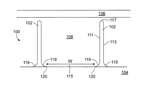
[0027] Figure 1 is a cross-sectional view of a portion of a centrifugal
impeller 100 taken
normal to an axis of rotation A of the impeller 100 and with the flowpath
surface 115 laid flat for
clarity. It is understood that an unaltered flowpath surface 115 would be
curved owing to the
annular nature of the hub 104 when viewed normal to the axis. Impeller 100
comprises a
plurality of vanes 102 circumferentially spaced about and coupled to a hub
104. Impeller 100 is
at least partially encased by a shroud 106. In some embodiments, the impeller
100 may be a
shrouded impeller, with the shroud integrally formed with or coupled to the
vanes 102.
[0028] Each vane 102 extends from a leading edge 147 (shown on Fig. 3) to
a trailing
edge 148 (shown on Fig. 3) and comprises a pressure side 111 and suction side
113. Each vane
102 extends outward from the hub 104 and terminates at a vane tip 117. The
vane tip 117 is
RCA12127CA 6
DM2\9935632 1
CA 3049046 2019-07-10
typically spaced from the shroud 106 a sufficient distance to minimize or
prevent contact
between the vane 102 and shroud 106 during operation.
[0029] A fillet 119 is provided on both the pressure side 111 and suction
side 113 to
smoothly transition between the vane 102 and hub 104. The fillet 119 of the
pressure side 111
(i.e. the pressure-side fillet) and the fillet 119 of the suction side 113
(i.e. the suction-side fillete)
may each extend from the leading edge 147 to the trailing edge 148 of the
vane. Each fillet 119
has a runout 120 defined at the intersection of the fillet 119 and the
flowpath surface 115. The
runout 120 thus comprises a line extending along the length of the fillet 119.
[0030] The hub 104 comprises an outwardly facing surface referred to as
the flowpath
surface 115. The flowpath surface 115 may face predominantly radially outward
proximate an
impeller inlet 122 (shown in Figure 3) and may face predominantly axially
forward proximate an
impeller discharge 124 (shown in Figure 3). The flowpath surface 115 extends
between the
runouts 120 of the fillets 119 of adjacent vanes 102, and has a width W
illustrated in Figure 1.
When viewed normal to the axis, the runouts 120 may also be referred to as
tangency points.
The flowpath surface 115 may therefore be the exposed portion of the hub 104,
which is to say
the portion of the hub 104 that is contacted by fluid flowing through the
impeller 100. The
flowpath surface 115 of the hub 104 does not include the vanes 102 or fillets
119. The hub 104
has an axis of rotation that is the axis of rotation of the impeller 100. The
hub 104 of known
centrifugal impellers 100 is axisymmetric, i.e., symmetric about the axis of
rotation.
100311 Figure 3 is a cross-sectional view of a portion of the centrifugal
impeller 100 of
Figure 1 taken along the intersection of a fillet 119 and the flowpath surface
115 (i.e. along a
runout 120). The flowpath surface 115 extends from an impeller inlet 122 to an
impeller
discharge 124 in a curved (e.g.,parabolic) and axisymmetric manner. Design of
the hub 104
RCA12127CA 7
DM2\9935632 1
CA 3049046 2019-07-10
often involves designating a curve between the impeller inlet 122 and impeller
discharge 124 and
then rotating the curve around the axis of rotation A to form a flowpath
surface 115. The
flowpath surface 115 may be parabolic in cross-section from inlet to
discharge.
[0032]
Figure 4 provides an isometric view of a portion of a centrifugal impeller
100.
The portion includes a pair of vanes 102 circumferentially spaced apart on the
flowpath surface
115. The vanes 102 may extend from the impeller inlet 122 to the impeller
discharge 124. A
splitter vane 127 may be disposed between the vanes 102, and may extend from
an intermediate
meridional position to the impeller discharge 124. For example, the splitter
vane 127 of Figure 4
begins at a meridional position of approximately 0.3 or greater. The meridian
of the impeller
100 extends from the impeller inlet 122 to the impeller discharge 124, such
that the leading edge
147 is at a meridional position of 0.0 and the trailing edge 148 is at a
meridional position of 1Ø
A meridional cross-section is taken normal to the meridian.
[0033]
As shown in Figures 1 and 2, a fluid flowpath 108 is defined between the vanes
102, flowpath surface 115, and shroud 106.
The vanes 102 predominantly provide
circumferential bounding of the fluid flowpath 108, while the flowpath surface
115 is a radially
inner boundary and the shroud 106 is a radially outer boundary. Due to the
curvature of the
flowpath surface 115 and shroud 106, proximate the impeller discharge 124 the
flowpath surface
115 and shroud 106 may be axial boundaries rather than radial boundaries.
[0034]
During operation, the impeller 100 is rotated at relatively high speeds about
the
axis of rotation. A fluid, typically air, is supplied at the impeller inlet
122 and flows through the
fluid flowpath 108 to the impeller discharge 124.
[0035]
Bulk flow of the fluid through the fluid flowpath 108 is, in Figure 1, into
the page.
However, in addition to bulk flow, may centrifugal impellers 100 experience
substantial levels of
RCA12127CA 8
DM2\9935632 1
CA 3049046 2019-07-10
secondary flow. Secondary flows may cause flow losses ¨ thus reducing the
efficiency of the
impeller 100 ¨ and reduce uniformity of fluid flow at the impeller discharge
124. Figure 2 is a
profile view of the predominant secondary flow 125 during operation of the
centrifugal impeller
100 of Figure 1. The illustrated impeller 100 is rotating from right to left.
[0036] The predominant secondary flow 125 is shown flowing from the lower
pressure
side 111 of a vane 102 toward the lower suction side 113 of an adjacent vane
102, along the
flowpath surface 115. The predominant secondary flow 125 is then directed by
the adjacent vane
102 in a radially outward direction and flows along the adjacent vane 102
toward the shroud 106.
The predominant secondary flow 125 is then directed circumferentially along
the shroud 106.
This pattern of predominant secondary flow 125 may create substantially cross
flow between the
vanes 102 of an impeller 100.
[0037] Figures 5 and 6 each present additional examples of the
inconsistent flow Mach
numbers experienced during operation of impeller 100. Figure 5 is a profile
view of the
predominant secondary flow at a first meridional position, and Figure 6 is a
profile view of the
predominant secondary flow at a second meridional position, during operation
of the centrifugal
impeller of Figure 1.
[0038] As shown in Figure 5, a region of relatively low flow Mach number
541 may
form along the lower pressure side 111 of a first vane 102 (shown on the right
side of Figure 5)
and along the adjacent portions of the flowpath surface 115. A region of
relatively high flow
Mach number 542 may form along the suction side 113 of an adjacent vane 102
(shown on the
left side of Figure 5) and along adjacent portions of the shroud 106. As in
Figure 2, the pressure
gradient between the region of relatively low flow Mach number 541 and the
region of relatively
high flow Mach number 542 may result in cross-flow or other secondary flows.
RCA12127CA 9
DM2\9935632 1
CA 3049046 2019-07-10
[0039] Similarly, Figure 6 illustrates a pair of regions of relatively
low flow Mach
numbers 641 forming along the pressure side 111 of a vane 102 (shown on the
right side of
Figure 6) and a splitter vane 127, and adjacent portions of the flowpath
surface 115. Regions of
relatively high flow Mach number 642 may form along the suction side 113 of an
adjacent vane
102 (shown on the left side of Figure 6) and along adjacent portions of the
shroud 106. As in
Figure 2, the pressure gradient between the regions of relatively low flow
Mach number 641 and
the regions of relatively high flow Mach number 642 may result in cross-flow
or other secondary
flows.
[0040] Figure 7 provides a cross-sectional view of a portion of a
centrifugal impeller 100
taken normal to an axis of rotation of the impeller 100 and laid flat for
clarity, in accordance with
some embodiments of the present disclosure. The illustrated centrifugal
impeller 100 has a non-
axisymmetric flowpath surface 731 tailored to reduce vane-to-vane secondary
flows in the
impeller 100.
[0041] An axisymmetric flowpath surface 115 such as that described with
respect to
Figure 1 is illustrated as a dashed line. The flowpath surface 731 of the
impeller 100 of Figure 7
diverges from the axisymmetric flowpath surface 115 so as to be non-
axisymmetric. The
flowpath surface 731 may also be asymmetric when viewed in a meridional and/or
axial plane.
Further, the runout 120 of the fillet 119 on the pressure side 111 of a vane
102 may be
asymmetric the runout 120 of the fillet 119 on the suction side 113 of the
vane 102.
[0042] In the illustrated embodiment, the flowpath surface 731 extends
linearly from the
runout 120 of a fillet 119 on the pressure side 111 of a vane 102 to the
runout 120 of a fillet 119
on the suction side 113 of an adjacent vane 102. The flowpath surface 731 may
extend between
RCA12127CA 10
DM2\9935632 1
CA 3049046 2019-07-10
the runouts 120 in a curvilinear or parabolic shape when viewed as a cross-
section taken normal
to the axis of rotation.
[0043] The runout 120 of the fillet 119 on the pressure side 111 is
higher, or further from
the axis of rotation, than the runout 120 of the fillet 119 on the the suction
side 113 of the
adjacent vane 102. The runout 120 of the fillet 119 may be higher, or further
from the axis of
rotation, than an axisymmetric flowpath surface 115 proximate the pressure
side 111 of a vane.
Proximate the suction side 113 of a vane the runout 120 of the fillet 119 may
be lower, or closer
to the axis of rotation, than an axisymmetric flowpath surface 115. However,
in some
embodiments the runout 120 may be higher, or further from the axis of
rotation, than an
axisymmetric flowpath surface 115 proximate the suction side 113 of a vane
while the runout
120 may be lower, or closer to the axis of rotation, than an axisymmetric
flowpath surface 115
proximate the pressure side 111 of a vane.
[0044] The altered flowpath geometry presented in Figure 7 may be used to
reduce
secondary flows through the flowpath 108. The flowpath surface 731 may be
contoured to more
closely align with the Mach number countours of impeller flow, such that the
flowpath surface
731 or overall impeller geometry reduces the differences in Mach number to
reduce secondary
flows.
[0045] The divergence between non-axisymmetric flowpath surface 731 and
axisymmetric flowpath surface 115 may be measured by an angle 0 between the
surfaces. In
some embodiments, angle 0 may be between 0 and 10 degrees.
[0046] The runout 120 along the fillet 119 of the pressure side 111 of a
vane 102 may be
asymmetric to the runout 120 along the fillet 119 of the suction side 113 of
the same vane 102.
RCA12127CA 11
DM2\9935632 1
CA 3049046 2019-07-10
The runout 120 along the fillet 119 of the pressure side 111 of a vane 102 may
be asymmetric to
the runout 120 along the fillet 119 of the suction side 113 of an adjacent
vane 102.
[0047] Departures from an axisymmetric flowpath surface 115 such as those
depicted in
Figure 7 may extend fully from the impeller inlet 122 to the impeller
discharge 124. However,
such departures may also extend for limited portions of the length of the
flowpath. Figures 8 and
9 provide cross-sectional views of a portion of the centrifugal impeller 100
of Figure 7 taken
along the fillet ¨ flowpath surface intersection (i.e. along a runout 120) on
the pressure side 111
of a vane 102 and the suction side 113 of an adjacent vane 102, in accordance
with some
embodiments of the present disclosure.
[0048] In the embodiment of Figure 8, the runout 120 has a maximum
departure from an
axisymmetric flowpath surface 115 at a knee 833 of the impeller 100. The knee
833 may be at a
meridional position of 0.5. In some embodiments, splitter vanes 127 may begin
at the knee 833,
and may extend from the knee 833 to the impeller discharge 124.
[0049] The flowpath surface 731 taken at the runout 120 on the pressure
side 111 may be
higher (further from the axis of rotation) than an axisymmetric flowpath
surface 115. The
flowpath surface 731 taken at the runout 120 on the suction side 113 may be
lower (closer to the
axis of rotation) than an axisymmetric flowpath surface 115. The flowpath
surface 731 taken
both proximate to the pressure side 111 and the suction side 113 may be non-
parabolic.
[0050] The runout 120 may return to an axisymmetric and/or parabolic
flowpath surface
115 proximate the impeller inlet 122 and/or impeller discharge 124. In the
illustrated
embodiment, the runouts 120 proximate the pressure side 111 and suction side
113 each return to
an axisymmetric and parabolic flowpath surface 115 at a meridional position of
approximately
0.2 and 0.8. In some embodiments, the runout 120 may return to an axisymmetric
and/or
RCA12127CA 12
DM2\9935632 1
CA 3049046 2019-07-10
parabolic flowpath surface 115 at a first meridional position proximate the
pressure side 111 and
at a second meridional position proximate the suction side 113.
[0051] The runout 120 may have a maximum departure from an axisymmetric
flowpath
surface 115 at knee 833. The runout 120 may have a maximum departure from an
axisymmetric
flowpath surface 115 at a meridional position of 0.5. In some embodiments, the
runout 120 may
have a maximum departure from an axisymmetric flowpath surface 115 at a
meridional position
of between 0.2 and 0.8.
[0052] The axisymmetric flowpath surface 115 of Figure 8 may be
parabolic. The
=outs 120 at the pressure side 111 and suction side 113 may be non-parabolic.
The runouts
120 at the pressure side 111 and suction side 113 may comprise a plurality of
curves having
different foci.
[0053] When the meridional position is considered in quartiles, the
embodiment of
Figure 8 presents a runout that is axisymmetric for at least a portion of the
first and fourth
quartiles while also non-axisymmetric for at least a portion of the second and
third quartiles.
[0054] Figure 8 may also depict the pressure side 111 and suction side
113 of the same
vane 102. Thus the runouts 120 depicted in Figure 8 illustrate that a flowpath
surface 731 along
the fillet 119 of the pressure side 111 of a vane 102 may be asymmetric to the
flowpath surface
731 along the fillet 119 of the suction side 113 of the same vane 102 or an
adjacent vane 102.
The asymmetry may extend along the full length of the vane 102, or may extend
for only a
portion of the length of the vane 102. For example, runout 120 along the
fillet 119 of the
pressure side 111 of a vane 102 may be asymmetric to runout 120 along the
fillet 119 of the
suction side 113 of the same vane 102 or an adjacent vane 102 for a first
portion of the length of
the vane 102. The runout 120 along the fillet 119 of the pressure side 111 of
a vane 102 may be
RCA12127CA 13
DM2 \9935632
CA 3049046 2019-07-10
symmetric to runout 120 along the fillet 119 of the suction side 113 of the
same vane 102 or an
adjacent vane 102 along a second portion of the vane 102.
[0055] In the embodiment of Figure 8, the first portion may be proximate
the knee 833
and/or a meridional position of 0.5. The maximum asymmetry between runout 120
along the
fillet 119 of the pressure side 111 of the vane 102 and runout 120 along the
fillet 119 of the
suction side 113 of the same vane 102 may be proximate the knee 833 and/or a
meridional
position of 0.5.
[0056] In some embodiments, such as that presented in Figure 9, the
runout 120 has a
maximum departure from an axisymmetric flowpath surface 115 proximate or at
the impeller
discharge 124. The runout 120 may have a maximum departure from an
axisymmetric flowpath
surface 115 proximate or at a meridional position of 1Ø
[0057] The flowpath surface 731 taken at the runout 120 on the suction
side 113 may be
higher than and/or axially forward from an axisymmetric flowpath surface 115.
The flowpath
surface 731 taken at the runout 120 on the pressure side 111 may be lower than
and/or axially aft
of an axisymmetric flowpath surface 115. The flowpath surface 731 taken both
proximate to the
pressure side 111 and the suction side 113 may be non-parabolic.
[0058] The flowpath surface 731 may diverge from an axisymmetric and/or
parabolic
flowpath surface 115 proximate the knee 833 and/or a meridional position of
0.5. The flowpath
surface 731 may begin to diverge from an axisymmetric and/or parabolic
flowpath surface 115 at
a point between a meridional position of 0.4 and 0.6. In some embodiments, the
flowpath
surface 731 may begin to diverge from an axisymmetric and/or parabolic
flowpath surface 115 at
a first meridional position proximate the pressure side 111 and at a second
meridional position
proximate the suction side 113. The flowpath surface 731 may be axisymmetric
and/or parabolic
RCA12127CA 14
DM2\9935632 1
CA 3049046 2019-07-10
between the leading edge of a vane 102 and the leading edge of the splitter
vane 127, and then
begin to diverge from an axisymmetric and/or parabolic flowpath surface 115 at
the leading edge
of the splitter vane 127.
[0059] The flowpath surface 731 of Figure 9 may improve the flow quality
and/or
uniformity at the impeller discharge 124, and thus improve flow quality and/or
uniformity of
flow into a centrifugal diffuser or deswirler.
[0060] The axisymmetric flowpath surface 115 of Figure 9 may be parabolic.
The
runouts 120 at the pressure side 111 and suction side 113 may be non-
parabolic. The runouts
120 at the pressure side 111 and suction side 113 may comprise a plurality of
curves having
different foci.
[0061] When the meridional position is considered in quartiles, the
embodiment of
Figure 9 presents a runout that is axisymmetric for at least a portion of the
first and second
quartiles while also non-axisymmetric for at least a portion of the third and
fourth quartiles.
[0062] Figure 9 may also depict the pressure side 111 and suction side 113
of the same
vane 102. Thus the runouts 120 depicted in Figure 8 illustrate that a runout
120 along the fillet
119 of the pressure side 111 of a vane 102 may be asymmetric to runout 120
along the fillet 119
of the suction side 113 of the same vane 102 or an adjacent vane 102. The
asymmetry may
extend along the full length of the vane 102, or may extend for only a portion
of the length of the
vane 102. For example, a runout 120 along the fillet 119 of the pressure side
111 of a vane 102
may be asymmetric to the runout 120 along the fillet 119 of the suction side
113 of the same
vane 102 or an adjacent vane 102 for a first portion of the length of the vane
102. The runout
120 along the fillet 119 of the pressure side 111 of a vane 102 may be
symmetric to the runout
RCA12127CA 15
DM2\9935632 1
CA 3049046 2019-07-10
120 along the fillet 119 of the suction side 113 of the same vane 102 or an
adjacent vane 102
along a second portion of the vane 102.
[0063] In the embodiment of Figure 9, the first portion may be proximate
the impeller
discharge 124 and/or a meridional position of 1Ø The maximum asymmetry
between the runout
120 along the fillet 119 of the pressure side 111 of the vane 102 and the
runout 120 along the
fillet 119 of the suction side 113 of the same vane 102 may be proximate the
impeller discharge
124 and/or a meridional position of 1Ø
[0064] The divergence from an axisymmetric flowpath surface 115, such as
that shown
by flowpath surface 731 of Figure 7, may continue with a splitter vane 127
disposed between the
adjacent vanes 102. Such an embodiment is illustrated in Figure 10. The
splitter vane 127 may
extend from a leading edge 147 to a trailing edge 148 and comprising a fillet
119 on each of the
pressure side 111 and suction side 113. The splitter vane 127 may extend from
the knee 833
and/or a meridional position proximate 0.5 to the impeller discharge 124
and/or a meridional
position proximate 1Ø In some embodiments the splitter vane 127 extends from
a meridional
position of 0.3 or 0.35 to the impeller discharge 124 and/or a meridional
position proximate 1Ø
[0065] A flowpath surface 1036 extends generally from a runout 120 on the
pressure side
111 of a vane 102 to the runout 120 on the suction side 113 of an adjacent
vane 102 and is
intersected by a splitter vane 127. The flowpath surface 1036 is thus defined
as a first portion
1038 extending between the runout 120 on the pressure side 102 of a vane 102
and the runout
120 on the suction side 113 of a splitter vane 127, and a second portion 1039
extending between
the runout 120 on the pressure side 102 of a splitter vane 127 and the runout
120 on the suction
side 113 of a vane 102.
RCA12127CA 16
DM2\9935632 1
CA 3049046 2019-07-10
[0066] The divergence between non-axisymmetric flowpath surface 1036 and
axisymmetric flowpath surface 115 may be measured by an angle 0 between the
surfaces. In
some embodiments, angle 0 may be between 0 and 10 degrees.
[0067] As shown in Figure 10, the runout 120 at a fillet 119 of the
pressure side 111 of a
vane 102 may be asymmetric with the runout 120 at each of the fillets 119 at
the suction side 113
and pressure side 111 of an adjacent splitter vane 127 and the suction side
113 of an adjacent
vane 102.
[0068] In still further embodiments, the runout 120 at a fillet 119 of the
pressure side 111
of a vane 102 may be asymmetric the runout 120 at a fillet 119 of the pressure
side 111 of an
adjacent vane 102.
[0069] The divergence from an axisymmetric flowpath surface 115 such as
that shown by
flowpath surface 731 of Figure 7 may be determined between any two adjacent
vanes 102, to
include an adjacent vane 102 and splitter vane 127. Such an embodiment is
illustrated in Figure
11.
[0070] In Figure 11, a flowpath surface 1137 comprises a first flowpath
surface segment
1143 and a second flowpath surface segment 1144. The first flowpath surface
segment 1143
extends between a runout 120 on a pressure side 111 of a vane 102 and a runout
120 on a suction
side 113 of a splitter vane 127. The second flowpath surface segment 1144
extends between a
runout 120 on a pressure side 111 of a splitter vane 127 and a runout 120 on a
suction side 113 of
a vane 102.
[0071] The runout 120 on the pressure side 111 of vane 102 and the runout
120 on the
pressure side 111 of splitter vane 127 may have a common divergence from an
axisymmetric
flowpath surface 115 (i.e. may be equally distant from the axis of rotation).
Similarly, the runout
RCA12127CA 17
DM2\9935632 i
CA 3049046 2019-07-10
120 on the suction side 113 of a splitter vane 127 and the runout 120 on the
suction side 113 of a
vane 102 may have a common divergence from an axisymmetric flowpath surface
115 (i.e. may
be equally distant from the axis of rotation). However in some embodiments the
runouts 120 on
a common side of adjacent vanes and/or splitter vanes may have varying
divergences from an
axisymmetric flowpath surface 115.
[0072] As shown in Figure 11, the runout 120 at a fillet 119 of the
pressure side 111 of a
vane 102 may be asymmetric with the runout 120 at the fillet 119 at the
suction side 113 of an
adjacent splitter vane 127 and the suction side 113 of an adjacent vane 102.
The runout 120 at a
fillet 119 of the pressure side 111 of a vane 102 may be symmetric with the
runout 120 at the
fillet 119 at the pressure side 111 of an adjacent splitter vane 127 and the
fillet 119 at the
pressure side 111 of an adjacent vane 102.
[0073] In still further embodiments, the runout 120 at a fillet 119 of
the pressure side 111
of a vane 102 may be asymmetric the runout 120 at a fillet 119 of the pressure
side 111 of an
adjacent vane 102.
[0074] In some embodiments the divergence between non-axisymmetric
flowpath surface
1137 and axisymmetric flowpath surface 115 may be measured by an angle 0
between the
surfaces. In some embodiments, angle 0 may be between 0 and 10 degrees. In
some
embodiments the divergence as measured by an angle 0 may be different between
the first
flowpath surface segment 1143 and the second flowpath surface segment 1144.
[0075] As described above with reference to Figure 7, the embodiments of
Figures 10
and 11 may be used to reduce secondary flows through the flowpath 108 and/or
improve
secondary flows proximate the impeller discharge 124.
RCA12127CA 18
DM2 \ 9935632 1
CA 3049046 2019-07-10
[0076] The present disclosure provides many advantages over existing
centrifugal
impellers. The disclosed centrifugal impeller may obtain an improved
efficiency and uniformity
of gas discharge by adjusting the flowpath surface of the hub to more evenly
distribute flow
Mach numbers between the impeller vanes. More evenly distributed flow Mach
numbers may
reduce the tendency of cross flow to form from regions of relative low flow
Mach number to
regions of relatively high flow Mach number.
[0077] The present disclosure also provides for influencing cross flow and
secondary
flows of an impeller without altering or substantially altering the geometry
of an impeller shroud
and/or the impeller vanes. Thus a consistent vane profile is presented to the
shroud, and the
present disclosure does not increase the risk of impingement of the vanes
against the shroud.
[0078] Although examples are illustrated and described herein, embodiments
are
nevertheless not limited to the details shown, since various modifications and
structural changes
may be made therein by those of ordinary skill within the scope and range of
equivalents of the
claims.
RCA12127CA 19
DM2\9935632 1
CA 3049046 2019-07-10