Note: Descriptions are shown in the official language in which they were submitted.
CA 03049204 2019-07-03
WO 2018/132197 PCMJS2017/064370
MELT INFILTRATION WITH SiGa AND/OR San ALLOYS
FIELD
[00011 The present invention generally relates to ceramic matrix composite
(CM() articles and
processes for their production. More particularly, a melt infiltration process
is provided that uses an
infiltrant that contains Ga, In, and/or B (e.g., of a silicon-gallium alloy
and/or a silicon-indium alloy)
to form silicon carbide fiber reinforced silicon carbide composites.
BACKGROUND
[0002] Higher operating temperatures for gas turbine engines are
continuously sought in order to
increase their efficiency. Though significant advances in high temperature
capabilities have been
achieved through formulation of iron, nickel and cobalt-base superalloys,
alternative materials have
been investigated. CMC materials are a notable example because their high
temperature capabilities
can significantly reduce cooling air requirements. CMC materials generally
comprise a ceramic fiber
reinforcement material embedded in a ceramic matrix material. The
reinforcement material may be
discontinuous short fibers dispersed in the matrix material or continuous
fibers or fiber bundles
oriented within the matrix material, and serves as the load-bearing
constituent of the CMC. In turn,
the ceramic matrix protects the reinforcement material, maintains the
orientation of its fibers, and
serves to dissipate loads to the reinforcement material. Individual fibers
(filaments) are often coated
with a release agent, such as boron nitride (BN), to form a de-bond layer that
allows for limited and
controlled slip between the fibers and the ceramic matrix material.
[0003] Continuous fiber reinforced ceramic composites (CFCC) are a type of
CMC that offers
light weight, high strength, and high stiffness for a variety of high
temperature load-bearing
applications, including shrouds, combustor liners, vanes, blades, and other
high-temperature
components of gas turbine engines. A CFCC material is generally characterized
by continuous fibers
(filaments) that may be arranged to form a unidirectional array of fibers, or
bundled in tows that are
arranged to fonft a unidirectional array of tows, or bundled in tows that are
woven to form a two-
dimensional fabric or woven or braided to form a three-dimensional fabric. For
three-dimensional
fabrics, sets of unidirectional tows may, for example, be interwoven
transverse to each other. Of
particular interest to high-temperature applications are silicon-based
composites, such as silicon
carbide (SiC) as the matrix and/or reinforcement material. SiC fibers have
also been used as a
reinforcement material for a variety of other ceramic matrix materials,
including titanium carbide
(TiC), silicon nitride (Si3N4), and alumina (A1203).
1
CA 03049204 2019-07-03
WO 2018/132197 PCT/US2017/064370
[0004] The fabrication of CMCs typically involves the use of multiple
prepreg layers, each in the
form of a "tape" comprising the desired ceramic fiber reinforcement material,
one or more precursors
of the CMC matrix material, and organic resin binders. According to
conventional practice, prepreg
tapes can be formed by impregnating the reinforcement material with a slurry
that contains the
ceramic precursor(s) and binders. Preferred materials for the precursor will
depend on the particular
composition desired for the ceramic matrix of the CMC component, for example,
SiC powder and/or
one or more carbon-containing materials that are ultimately converted to SiC
upon reaction with
molten Si. Other typical slurry ingredients include organic binders that
promote the pliability of
prepreg tapes, and solvents for the binders that promote the fluidity of the
slurry to enable
impregnation of the fiber reinforcement material
[0005] After allowing the slurry to partially dry and, if appropriate,
partially curing the binders
(B-staging), the resulting prepreg tape is laid-up with other tapes, and then
debulked and, if
appropriate, cured while subjected to elevated pressures and temperatures to
produce a preform. The
preform is then heated (fired) in a vacuum or inert atmosphere to decompose
the binders, remove
solvents, and convert the precursor to the desired ceramic matrix material.
Due to decomposition of
the binders, the result is a porous CMC body that may undergo melt
infiltration (MI) to fill the
porosity and yield the CMC component. Melt-infiltration processes used to
produce SiC matrices
generally entail infiltrating the porous CMC body with molten silicon supplied
externally. The
molten silicon infiltrates into the porosity, reacts with the carbon content
of the matrix to form
silicon carbide, and fills the porosity to yield the desired CMC component.
[0006] CMCs and CFCCs articles produced to contain silicon carbide fibers
in a silicon carbide
matrix in the manner discussed above contain residual silicon metal, which is
typically in a
continuous phase interwoven between silicon carbide grains that have a small
grain size and limited
connectivity between adjacent grains.
[0007] This silicon phase softens and eventually melts at temperature
exceeding about 1204 C,
limiting the capability of the MI CMC. Moreover, even if the silicon phase is
removed by an
extraction process, the resulting silicon carbide material in the CMC is
porous and not well-
connected, making it a weak phase relative to the fiber. Thus, mechanical load
that can be applied is
limited at temperatures exceeding 1204 C even for silicon extracted CMC,
since the matrix can
crack effectively transferring the load completely to the fibers. Such
phenomena results in short
creep rupture lives.
[0008] As such, a need exists for an improved CMC with higher temperature
capabilities, along
with methods of its manufacture.
2
CA 03049204 2019-07-03
WO 2018/132197 PCT/US2017/064370
BRIEF DESCRIPTION
[0009] Aspects and advantages will be set forth in part in the following
description, or may be
obvious from the description, or may be learned through practice of the
invention.
[0010] Methods are generally provided for forming a ceramic matrix
composite (CMC). In one
embodiment, the method includes melt infiltrating a silicon mixture into a
ceramic matrix composite
preform, with the silicon mixture including SiGa,In, or a mixture thereof For
example, the silicon
mixture may include silicon metal in combination with SiGa, SiIn, or the
mixture thereof In one
embodiment, the silicon mixture further includes B within the SiGa, SiIn, or
the mixture thereof
(e.g., in the form of SiBGa, SiBIn, or a mixture thereof).
[0011] In one embodiment, the silicon mixture is melt infiltrated into the
ceramic matrix
composite preform at an infiltration temperature that is about 1414 C or less
(e.g., at an infiltration
temperature that is about 1375 C to about 1410 C). In an alternative
embodiment, the silicon
mixture is melt infiltrated into the ceramic matrix composite preform at an
infiltration temperature of
about 1415 C or higher (e.g., about 1420 C to about 1500 C).
[0012] The method may further include, after melt infiltration, extracting
any residual Ga and/or
In from the CMC.
[0013] These and other features, aspects and advantages will become better
understood with
reference to the following description and appended claims. The accompanying
drawings, which are
incorporated in and constitute a part of this specification, illustrate
embodiments of the invention
and, together with the description, serve to explain certain principles of the
invention.
BRIEF DESCRIPTION OF THE DRAWINGS
[0014] A full and enabling disclosure of the present invention, including
the best mode thereof
directed to one of ordinary skill in the art, is set forth in the
specification, which makes reference to
the appended Figs., in which:
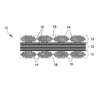
[0015] FIG. 1 schematically represents a fragmentary cross-sectional view
of an exemplary
CFCC article;
[0016] FIG. 2 shows a phase diagram for SiGa and indicates that the melting
point of SiGa
decreases as the relative amount of Ga increases; and
[0017] FIG. 3 shows a phase diagram is shown for SiIn and indicates that
the melting point of
SiIn decreases as the relative amount of In increases.
[0018] Repeat use of reference characters in the present specification and
drawings is intended to
represent the same or analogous features or elements of the present invention.
3
CA 03049204 2019-07-03
285678-3
DETAILED DESCRIPTION OF PARTICULAR EMBODIMENTS
[0019] Reference now will be made in detail to embodiments of the invention,
one or more
examples of which are illustrated in the drawings. Each example is provided by
way of explanation
of the invention, not limitation of the invention. In fact, it will be
apparent to those skilled in the art
that various modifications and variations can be made in the present invention
without departing
from the scope of the invention. For instance, features illustrated or
described as part of one
embodiment can be used with another embodiment to yield a still further
embodiment. Thus, it is
intended that the present invention covers such modifications and variations
as come within the
scope of the appended claims and their equivalents.
[0020] As used herein, the terms -first-, "second", and -third- may be used
interchangeably to
distinguish one component from another and are not intended to signify
location or importance of
the individual components.
[0021] Chemical elements are discussed in the present disclosure using their
common chemical
abbreviation, such as commonly found on a periodic table of elements. For
example, hydrogen is
represented by its common chemical abbreviation H; helium is represented by
its common chemical
abbreviation He: and so forth.
[0022] Methods are generally provided for forming CMC articles, including CFCC
articles,
which may be used at operating temperatures exceeding the melting point of low-
melting silicon
alloys (for example, about 1357 C.) and exceeding the melting point of
silicon and low-melting
alloys thereof (e.g., up to temperatures of at least 1480 C). In particular
embodiments. the CMC
materials are silicon containing CMC materials, such as CMC's containing
silicon carbide as the
reinforcement and/or matrix material, a particular example of which is
continuous silicon carbide
fibers in a matrix of silicon carbide. However, other silicon-containing
materials are also within
the scope of the invention, including ceramics such as silicon nitride and
silicides (intermetallics)
such as niobium silicide and molybdenum silicide.
[0023] In particular, melt infiltration techniques used during the formation
of the CMC
components are generally provided. In one embodiment, the melt infiltration
techniques utilize a
silicon infiltration mixture that also includes gallium (Ga), indium (In), or
a mixture thereof.
Without wishing to be bound by any particular theory, it is believed that the
inclusion of Ga and/or
In in the silicon infiltration mixture lowers the melting point of the silicon
infiltration mixture (from
pure silicon's melting point of about 1414 C). Referring to FIG. 2, a phase
diagram is shown for
SiGa. which shows that the melting point of SiGa decreases as the relative
amount of Ga increases.
Similarly. FIG. 3 shows a phase diagram is shown for Siln, which shows that
the melting point of
4
CA 03049204 2019-07-03
WO 2018/132197 PCT/US2017/064370
SiIn decreases as the relative amount of In increases. Since neither Ga and In
reacts with carbon,
they are rejected back into the melt mixture during infiltration to result in
even lower melting point
as the Si is being consumed, and ultimately, for the residual silicon. Thus,
removal of the residual
silicon may be easier and performed at lower temperatures via extraction as a
post-process. Ga and
In also do not attack SiC, so the risk of fiber attack using this molten
infiltrant is minimal.
[0024] Since the melting point of the Si-Ga and/or Si-In alloys are lower,
melt infiltration may be
performed at an infiltration temperature that is lower than 1414 C (i.e., the
melting point of Si), such
as about 1375 C to about 1410 C. Such lower temperatures allow for a more
efficient and cost
effective process for melt infiltration. Additionally, the resulting matrix
may have smaller grain size
that leads to higher tensile strength but less creep resistance. Such
properties may be desirable in
certain components. Alternatively, the infiltration temperature may be at the
1414 C or higher to
result in larger grain size and/or silicon carbide grains with better
connectivity throughout the matrix,
such as about 1415 C or higher (e.g., about 1420 C to about 1500 C). The
larger, more connected
grains with robust connection points may result in a silicon carbide matrix
that is more creep
resistant.
[0025] In one embodiment, the silicon mixture includes an atomic percent of
Ga and/or In of
about 0.1% to about 20% (e.g., about 0.5% to bout 10%) prior to melt
infiltrating the silicon mixture
into the preform. Then, as Si is consumed during the melt infiltration
process, the relative amounts
of Ga and/or In in the silicon infiltration mixture increases relative to Si
in order to further lower the
melting temperature of the silicon infiltration mixture. For example, in
particular embodiments, the
silicon mixture may include about 50 atomic % or greater (e.g., about 75
atomic % or greater) of the
Ga and/or In after melt infiltrating the silicon mixture into the ceramic
matrix composite preform.
[0026] As stated, the silicon mixture may include silicon metal in
combination with Ga and/or In,
such as in the form of SiGa and/or SiIn, respectively. Other materials may
also be included in the
silicon infiltration mixture, such as boron (B). For example, the silicon
mixture may include SiBGa
and/or SiBIn. Without wishing to be bound by any particular theory, it is
believed that the inclusion
of boron within the infiltrant mixture helps with wetting and complete melt
penetration throughout
the preform.
[0027] The following discussion of CMC articles makes reference to FIG. 1,
which shows an
exemplary CFCC component 10 comprising multiple laminae 12, each derived from
an individual
prepreg that originally comprised unidirectionally-aligned tows 14 impregnated
with a ceramic
matrix precursor. As a result of debulking, curing and firing the laminate
preform formed by the
stacked prepregs, each lamina 12 contains unidirectionally-aligned fibers 16
encased in a matrix 18
CA 03049204 2019-07-03
WO 2018/132197 PCT/US2017/064370
that includes a silicon carbide phase that may be formed in part by conversion
of the ceramic matrix
precursor during firing and melt infiltration.
[0028] As a CFCC component 10, the tows 14 are shown unidirectional in each
lamina 12, i.e.,
oriented side-by-side and parallel to each other. Suitable fiber diameters,
tow diameters and center-
to-center tow spacings will depend on the particular application, the
thicknesses of the laminae 12,
and other factors, and therefore are not represented to scale in FIG. 1. The
individual fibers 16 of the
tows 14 are, in one particular embodiment, coated with one or more release
agents to form a de-bond
fiber coating (not shown) that allows for limited and controlled slip between
the matrix 18 and the
tows 14 and their individual fibers 16. Suitable materials for the fiber
coating include boron nitride
(BN), silicon-doped BN, silicon nitride (Si3N4), silicon carbide (SiC),
hafnium carbide (HfC),
hafnium nitride (HfN), zirconium carbide (ZrC), zirconium nitride (ZrN),
tantalum carbide (TaC),
tantalum nitride (TaN), and mixtures thereof In one particular embodiment, the
fiber coating
comprises multiple layers of one or more of these compounds. As cracks develop
in the component
10, fibers 16 that bridge the crack act to redistribute the load to adjacent
fibers 16 and regions of the
matrix 18, thus inhibiting or at least slowing further propagation of the
crack.
[0029] In one embodiment, a prepreg process is used to manufacture the
ceramic matrix
composites. In such a process, a fiber tow is wound from a drum, and then
passed through a vessel
where a ceramic fiber coating is applied to the tow (e.g., via a chemical
vapor deposition (CVD)
process). This coating serves to protect the fibers during composite
processing and provides a low
strength fiber-matrix interface, thereby enabling the fiber matrix debonding
and fiber pull-out
"toughening" mechanisms. CMC's typically in the past used carbon as the fiber
coating, but have
since incorporated boron nitride or silicon-doped boron nitride for increased
oxidation resistance.
Following fiber coating, the fiber tow is pulled through a vessel containing a
slurry including the
preform matrix constituents (SiC and carbon particulate, binders and
solvents), and then wound on a
drum to form a unidirectional pre-impregnated, i.e., "pre-preg," tape.
[0030] During the fabrication of the component 10 a desired number of
prepreg tapes are laid-up
to form a preform that undergoes further processing to yield the component 10.
Each tape is formed
to contain a reinforcement architecture (formed by the fibers 16) encased
within a precursor of the
desired material for the matrix 18, e.g., SiC. Thus, the use of unidirectional
fiber prepreg tapes builds
up the composite structure. CMC architectures derived from unidirectional
prepreg offer improved
mechanical properties at elevated temperatures above the melting point of
silicon. It is believed that
because each fiber is well-isolated via the refractory matrix phase,
mechanical loads can be
transferred more efficiently to each individual fiber, which in turn promotes
improved mechanical
properties. According to conventional practice, such prepreg tapes can be
formed in a single
6
CA 03049204 2019-07-03
WO 2018/132197 PCT/US2017/064370
operation, for example, by applying a precursor-containing slurry during
winding of a continuous
strand of tow onto a drum. Following the winding operation, the slurry is
allowed to partially or
completely dried, removed from the drum, cut to shape, laid-up to give the
desired fiber architecture
and laminated to form a green composite preform.
[0031] The preform is then placed within a chamber where fiber coatings are
applied to the
preform using a chemical vapor infiltration (CVI) process. The preform is then
heated in vacuum or
in an inert atmosphere to decompose the organic binders and yield a porous
rigid preform. For
example, the laminate may be heated in nitrogen, argon, or vacuum to burn out
a portion of the
organic binders and resins within the pores, while also converting a portion
of the binders and resins
to carbon char. Machining of the preform can be done at this stage, which
helps to reduce the
amount of final machining of the part after final densification.
[0032] The burned-out porous laminate can then be melt infiltrated by
heating an external source
of silicon infiltration mixture that also includes Ga, In, or a mixture
thereof, as discussed above, such
that it melts and flows into the laminate. A first portion of this silicon
infiltration mixture reacts with
the precursor carbon in the porous laminate to form silicon carbide, and a
second portion of the
silicon infiltration mixture fills the porosity in the laminate. The melt
infiltration (MI) process is
particularly suitable for use after the preform was formed with a slurry that,
upon firing, results in a
carbon-containing preform that preferably reacts with molten silicon to form
silicon carbide. Carbon
additions can also be achieved by subjecting the porous preform to direct
infiltration of carbon black
particles or burnout of a carbon-yielding resin that had been infiltrated into
the pore space. In one
embodiment, the composite preform, containing the coated SiC fibers, SiC
and/or carbon
particulates, and organic binders in the prepreg case, is heated to the
infiltration temperature while in
contact with or in proximity to the silicon infiltration mixture (e.g., a
source of silicon metal that
includes Ga and/or In). The molten silicon metal readily wets SiC and/or
carbon, and therefore is
easily pulled into the remaining porosity of the preforms by a capillary
process. No external driving
force is needed for the infiltration and there is no dimensional change of the
composite preform.
[0033] Upon cooling, the silicon or silicon alloy filling the pore space
solidifies. This silicon or
silicon alloy is the desired phase to extract from the melt-infiltrated CMC to
form a porous preform.
In one embodiment, these processing techniques are intended to greatly improve
the temperature
capability of a CMC article produced by processing steps of the type described
above by reducing or
entirely eliminating porosity within the CMC article, as well as reducing or
entirely eliminating any
residual elemental silicon and/or low-melting silicon alloys in the CMC
article.
[0034] The densification processes noted above can benefit from the use of
certain prepreg
slurries that preferably do not leave residual elemental silicon or silicon
alloys in the porous preform,
7
CA 03049204 2019-07-03
WO 2018/132197 PCT/US2017/064370
and preferably yield a continuous network of silicon carbide or carbon to
provide strength within the
porous preform prior to infiltration. Various precursor-containing slurries
have been applied to
continuous fibers and tows to produce prepreg tapes. Typical slurry
compositions have contained, in
addition to the desired ceramic precursor(s), ceramic constituents of the
matrix (for example, silicon
carbide), organic resins that serve as processing aids (for example,
polyvinybutyral and poly isobutyl
methacrylate), solvents (for example, toluene, MIBK, ethylbenzene, etc.), and
plasticizers for the
binders (for example, dibutyl phthalate). The slurry compositions may contain
an approximately 1:1
stoichiometric mixture of elemental silicon and carbon black that react during
firing of the preform
(e.g., at temperatures of about 1430 C. to about 1460 C). Alternatively or
additionally, the slurry
composition may additionally contain one or more organic binders that can be
pyrolyzed to form a
network of carbon char (for example, furanic resins and/or phenolic resins).
In any case, the result is
preferably a cured and rigid preform that can be essentially free of elemental
silicon and silicon
alloys, and in which the fibers are encased in a porous yet continuous network
of silicon carbide
filaments or carbon char (depending on the particulars of the embodiment as
described above). This
porosity can then be eliminated by the densification processes discussed
above, such that the network
of silicon carbide filaments or carbon char provides a scaffold for
reinforcement to prevent cracking
due to the stresses involved in pyrolysis of the polymeric precursor,
particular during the first
densification cycle.
[0035] Additional processing steps can be performed to extract any residual
elemental silicon
and/or low-melting silicon alloy phase within the CMC article. An extraction
step is particularly
desirable if a slurry is used that contains an excess of elemental silicon
relative to what is needed for
a 1:1 stoichiometric mixture of elemental silicon and carbon black, or if a
slurry is used that does not
contain any elemental silicon and a melt infiltration step is performed using
an external source of
elemental silicon or a silicon alloy as the infiltrant. For the latter,
typical slurry compositions have
contained silicon carbide, carbon black, organic resins that serve as
processing aids (for example,
polyvinybutyral), organic resins that are pyrolyzed to form a network of
carbon char, solvents (for
example, toluene, MIBK, alcohols, and acetone), etc.), and plasticizers for
the binders (for example,
dibutyl phthalate).
[0036] A suitable extraction technique is a powder pack extraction process
that involves
surrounding the CMC article with a porous material and heating until the
silicon or silicon alloy is
molten. Porous materials may include, but are not limited to, carbon black,
graphite, industrial
diamond, silicon carbide, silicon nitride, molybdenum and its silicides,
carbides and nitrides,
tungsten and its silicides, carbides and nitrides, tantalum and its silicides,
carbides and nitrides,
and/or niobium and its silicides, carbides and nitrides. Preferred porous
materials include those that
8
CA 03049204 2019-07-03
285678-3
provide a chemical driving force to draw out the silicon or silicon alloy, do
not react strongly with
the silicon carbide in the melt-infiltrated body and, in case there is a
shallow reaction layer, are
easily removed by grinding or grit blasting to ensure that the pore network
left behind is open for
subsequent infiltration. Preferred porous materials include molybdenum,
tungsten. tantalum,
niobium metal, and niobium silicides. These materials are capable of
adequately extracting residual
silicon and silicon alloy and forming metal suicides on the surface of the CMC
article that are easily
removed by grit blasting to expose pore channels within the CMC article. Once
exposed, the pore
channels can be filled with one or more precursors that can be converted to
silicon carbide by a PIP,
MI, or CVI technique.
[0037] Another suitable extraction technique is a liquid phase extraction
process carried out by
exposing the CMC article to a liquid that is corrosive to residual silicon
alloy, but not to any other
components of the CMC article. Examples of such liquids are hydrofluoric acid
(HF). mixtures of
hydrofluoric acid and other acids, strongly basic solutions such as aqueous
NaOH, Li0H. KOH. etc..
liquid metals such as gallium, indium, tin, and mercury, and multistage
leaching processes that
involve liquid metals, acids, and bases. The liquid phases can be heated to
increase the rate at which
they dissolve the residual silicon alloy. This is particularly true for liquid
metals, which require an
elevated temperature to activate the silicon alloy removal process. Heat
treatments may be
performed to eliminate any contaminants, for example, to evaporate fluorine or
any metal in the pore
channels. As before, the exposed pore channels can be filled with one or more
precursors that can be
converted to silicon carbide by a PIP. MI, or CVI technique.
[0038] Another suitable extraction technique is vaporization of silicon or
silicon alloy at high
temperature in a strong vacuum. As before. the exposed pore channels can be
filled with one or
more precursors that can be converted to silicon carbide by a PIP, MI, or (NI
technique.
[0039] While various applications are foreseeable, particular applications for
the component 10
include components of gas turbine engines, such as combustor liners, blades,
vanes and shrouds
within the turbine sections of gas turbines.
[0040] This written description uses exemplary embodiments to disclose the
invention, including
the best mode, and also to enable any person skilled in the art to practice
the invention, including
making and using any devices or systems and performing any incorporated
methods. The patentable
scope of the invention may include other examples that occur to those skilled
in the art in view of
the description. Such other examples are intended to be within the scope of
the invention.
9