Note: Descriptions are shown in the official language in which they were submitted.
j1JIST HUMIDIFIrR PLOWER METHODS AND SYSTEMS
FIELD OF THE INVENTION
[001] This patent application relates to mist humidifiers and more
specifically to blower packs
for mist humidifiers.
BACKGROUND OF THE INVENTION
[002] A humidifier is a device, primarily an electrical appliance that
increases humidity
(moisture) in an environment, e.g. a single room or an entire building. In the
home, point-of-use
humidifiers are commonly used to humidify a single room, while whole-house or
furnace
humidifiers, which connect to a home's heating, ventilation and air
conditioning (HVAC) system,
provide humidity to the entire house. Medical ventilators often include
humidifiers for increased
patient comfort. Large humidifiers are used in commercial, institutional, or
industrial contexts,
often as part of a larger HVAC system. .
[003] Such humidifiers may exploit different techniques including, for
example, evaporative or
natural humidifiers employing a wick, vaporizers which heat or boil the water,
impeller
humidifiers, and ultrasonic humidifiers. Irrespective of the means of
introducing moisture into
the air this air must be moved from the humidifier into the environment in
order to humidify the
environment. Where the humidifier is integrated into a HVAC system then the
air mover is the
fan / blower within the furnace and/or air conditioner of the HVAC system.
However, in many
applications the humidifier is employed independent of any HVAC system and
accordingly there
exists a requirement for a standalone blower pack for use in conjunction with
the humidifier.
[004] Within prior art humidification systems recirculation of the air within
the humidifier can
result in condensation within the system after the chamber or chambers which
can subsequently
result in droplets being emitted / distributed from the humidifier into the
local environment,
commonly referred to as "spitting." Accordingly, it would be beneficial to
provide a distribution
means which efficiently distributes the mist into the air and avoids such
"spitting."
- 1 -
CA 3049382 2019-07-09
[005] It would be further beneficial for the distribution means to support
distribution of the mist
directly from the humidification system or remotely from the humidification
system via
intermediate ducting. It would be further beneficial for the distribution
means to support
"throwing" of the mist into the environment rather than relying upon
circulation within the
environment to achieve this.
[006] Other aspects and features of the present invention will become apparent
to those
ordinarily skilled in the art upon review of the following description of
specific embodiments of
the invention in conjunction with the accompanying figures.
SUMMARY OF THE INVENTION
[007] It is an object of the present invention to mitigate limitations within
the prior art relating
to mist humidifiers and more specifically to blower packs for mist
humidifiers.
[008] In accordance with an embodiment of the invention there is provided a
system
comprising:
a frame to which a mist channel and a pressurised box are mechanically
mounted;
the mist channel comprising:
an outlet disposed at one end; and
an inlet at another distal end of the mist channel;
the pressurised box comprising:
a first portion enclosing a first predetermined portion of the mist channel on
an upper side of the
mist channel having an opening at the outlet of the mist channel and an inlet
at a second
distal end;
a second portion enclosing a second predetermined portion of the mist channel
on a lower side of
the mist channel having an opening at the outlet of the mist channel and an
inlet at a
second distal end; wherein
at least one of a lower internal surface of the mist channel and an upper
internal surface of the
mist channel have a slope relative to a horizontal plane of the frame from the
outlet of the
mist channel towards the inlet of the mist channel.
- 2 -
CA 3049382 2019-07-09
10091 In accordance with an embodiment of the invention there is provided a
method of
transporting a mist of a liquid carried by a first gas into an environment
comprising:
providing a mist generator for generating a mist of a liquid within the first
gas;
providing a mist channel comprising an inlet for receiving an output of the
mist generator and an
outlet; and
providing a blower pack around the outlet of the mist channel for generating a
flow of a second
gas which is combined with a flow of mist from the outlet of the mist channel;
wherein
the blower pack provides for increased projection of the mist into the
environment.
100101 Other aspects and features of the present invention will become
apparent to those
ordinarily skilled in the art upon review of the following description of
specific embodiments of
the invention in conjunction with the accompanying figures.
BRIEF DESCRIPTION OF THE DRAWINGS
100111 Embodiments of the present invention will now be described, by way of
example only,
with reference to the attached Figures, wherein:
100121 Figure lA depicts exemplary configurations for mist humidifiers
exploiting blower packs
according to an embodiment of the invention;
[0013] Figure 1B depicts an exemplary configuration for a mist humidifier
exploiting a blower
pack according to an embodiment of the invention in direct connection to the
humidification
system;
[00141 Figure 2 depicts schematically the internal humidification and blower
pack elements of
the exemplary configuration of the mist humidifier depicted in Figure 18;
[0015] Figure 3A depicts the external shell of a blower pack element according
to an
embodiment of the invention as employed in the mist humidifiers depicted in
Figures IA and 1B
respectively;
[00161 Figure 3B depicts the blower pack element according to an embodiment of
the invention
as employed in the mist humidifiers depicted in Figures 1A and 18 respectively
as depicted in
Figure 3A in exploded form;
- 3 -
CA 3049382 2019-07-09
[0017] Figure 4 depicts the blower pack element according to an embodiment of
the invention as
employed in the mist humidifiers depicted in Figures 1A and 13 respectively as
depicted in
Figure 3A with only the front plate of the external shell;
[0018] Figures 5 and 6 respectively depict rear and front perspective views of
an exemplary
blower pack according to an embodiment of the invention;
[0019] Figures 7 and 8 respectively depict a side and cross-sectional side
elevation views of an
exemplary blower pack according to an embodiment of the invention;
[0020] Figure 9 depicts a rear side cross-sectional perspective view of an
exemplary blower pack
according to an embodiment of the invention;
[0021] Figure 10 depicts a side cross-sectional perspective view of an
exemplary blower pack
according to an embodiment of the invention;
[0022] Figures 11 and 12 respectively depict cross-sectional side elevation
views of the
pressurised box and mist channel for an exemplary blower pack according to an
embodiment of
the invention;
100231 Figures 13 and 14 respectively depict a front and side cross-sectional
elevation views of
the pressurised box and mist channel assembly for an exemplary blower pack
according to an
embodiment of the invention;
[0024] Figure 15 depicts a cross-sectional plan elevation view of the
pressurized box and mist
channel for an exemplary blower pack according to an embodiment of the
invention.
DETAILED DESCRIPTION
[0025] The present description is directed to mist humidifiers and more
specifically to blower
packs for mist humidifiers.
[0026] The ensuing description provides representative embodiment(s) only, and
is not intended
to limit the scope, applicability or configuration of the disclosure. Rather,
the ensuing description
of the embodiment(s) will provide those skilled in the art with an enabling
description for
implementing an embodiment or embodiments of the invention. It being
understood that various
= changes can be made in the function and arrangement of elements without
departing from the
spirit and scope as set forth in the appended claims. Accordingly, an
embodiment is an example
- 4 -
CA 3049382 2019-07-09
or implementation of the inventions and not the sole implementation. Various
appearances of
"one embodiment," "an embodiment" or "some embodiments" do not necessarily all
refer to the
same embodiments. Although various features of the invention may be described
in the context
of a single embodiment, the features may also be provided separately or in any
suitable
combination. Conversely, although the invention may be described herein in the
context of
separate embodiments for clarity, the invention can also be implemented in a
single embodiment
or any combination of embodiments.
[0027] Reference in the specification to "one embodiment", "an embodiment",
"some
embodiments" or "other embodiments" means that a particular feature,
structure, or
characteristic described in connection with the embodiments is included in at
least one
embodiment, but not necessarily all embodiments, of the inventions. The
phraseology and
terminology employed herein is not to be construed as limiting but is for
descriptive purpose
only. It is to be understood that where the claims or specification refer to
"a" or "an" element,
such reference is not to be construed as there being only one of that element.
It is to be
understood that where the specification states that a component feature,
structure, or
characteristic "may", "might", "can" or "could" be included, that particular
component, feature,
structure, or characteristic is not required to be included.
[0028] Reference to terms such as "left", "right", "top", "bottom", "front"
and "back" are
intended for use in respect to the orientation of the particular feature,
structure, or element within
the figures depicting embodiments of the invention. It would be evident that
such directional
terminology with respect to the actual use of a device has no specific meaning
as the device can
be employed in a multiplicity of orientations by the user or users.
[0029] Reference to terms "including", "comprising", "consisting" and
grammatical variants
thereof do not preclude the addition of one or more components, features,
steps, integers or
groups thereof and that the terms are not to be construed as specifying
components, features,
steps or integers. Likewise, the phrase "consisting essentially of', and
grammatical variants
thereof, when used herein is not to be construed as excluding additional
components, steps,
features integers or groups thereof but rather that the additional features,
integers, steps,
components or groups thereof do not materially alter the basic and novel
characteristics of the
- 5 -
CA 3049382 2019-07-09
claimed composition, device or method. If the specification or claims refer to
"an additional"
element, that does not preclude there being more than one of the additional
element.
[0030] A "mist humidifier" as used herein and throughout the disclosure may
comprise, but not
be limited to, a warm mist humidifier and/or a cool mist humidifier. A cool
mist humidifier may
exploit an internal wick filter to absorb water whilst an ultrasonic based
cool mist humidifier
uses ultrasonic vibration technology to create a micro-fine cool mist. A warm
mist humidifier
uses an internal heating element that boils water before releasing it. A mist
humidifier therefore
is a specific form of mist generator which generates a mist in that it creates
a mist of water
droplets. Other liquids may be employed.
100311 A "mist" as used herein and throughout the disclosure may comprise, but
not be limited
to, a suspension of small droplets of a liquid within a gas. For example, this
may be water in air.
[0032] Within the following description in respect of Figures lA to 15
respectively blower packs
according to embodiments of the invention are described and depicted in
conjunction with an
ultrasonic mist humidification unit. However, it would be evident that within
other embodiments
of the invention a blower pack according to an embodiment of the invention may
be employed
with humidification units exploiting other cool mist humidification techniques
and/or warm mist
humidification techniques.
100331 Further, within the following description in respect of Figures 1 A to
15 respectively
blower packs according to embodiments of the invention are described and
depicted in
conjunction with a separate humidification unit. However, it would be evident
that within other
embodiments of the invention the blower pack may form part of a single
integrated unit with the
humidification system.
[0034] Referring to Figure I A there are depicted first to fourth
configurations 100A to 100D
respectively for humidification systems exploiting blower packs according to
an embodiment of
the invention in conjunction with ultrasonic humidification units. First
configuration 100A
comprises a pair of blower packs 110A and 110B respectively coupled to a first
ultrasonic
humidification unit 130A via first and second ducting 150A and 150B
respectively. Second
= configuration similarly comprises a pair of blower packs 110C and 110D
respectively coupled to
a second ultrasonic humidification unit 130B via first ducting 150C to the
second blower pack
- 6 -
CA 3049382 2019-07-09
110D whilst other ducting is coupled to the first blower pack 10C on the other
side of a divider
140, e.g. a wall, to that of the second blower pack 110D.
[0035] Third configuration 100C comprises a single blower pack 110E coupled to
a third
ultrasonic humidification unit 120A via ducting 150D. Fourth configuration
100D comprises a
single blower pack 110F directly coupled to a fourth ultrasonic humidification
unit 120B. Figure
1B depicts a larger scale image of the fourth configuration 100D for a mist
humidifier with
blower pack 110F and ultrasonic humidification unit 120B.
[0036] Accordingly, through combinations of one or more blower packs with
different
humidification units a range of humidification capacities can be provided. For
example, a
humidification unit such as first ultrasonic humidification unit 130A or
second ultrasonic
humidification unit 130B may provide capacities up to 18kg/hr. (approximately
401b/hr.) in
modular increments of 6kg/hr. (approximately 131b/hr.) through a pair of
blower packs whilst
third ultrasonic humidification unit 120A and fourth ultrasonic humidification
unit 1208 may
provide capacities to 9kg/hr. (approximately 201b/hr.) in modular increments
of 3kg/hr.
(approximately 71b/hr.) with a single blower pack. Other capacities and
modularity may be
implemented as will be evident from the ensuing description.
[0037] Referring to Figure 2 there are depicted schematically the blower pack
element 200A of a
blower pack such as blower pack 110 in Figure IA and internal humidification
element 200B of
an ultrasonic humidification unit such as ultrasonic humidification unit 120B
in Figure 1B.
Accordingly, the blower pack element 200A comprises first to third inlets 210A
to 210C
respectively which are combined through the blower pack element 200A into
single outlet 240
together with air pulled in by the blower pack element 200A and combined with
the mist from
first to third inlets 210A to 210C respectively. Each of the first to third
inlets 210A to 210C is
coupled to a respective one of first to third outlets 220A to 220C of the
internal humidification
element 200B. The first to third outlets 220A to 220C receive misted air from
the misting
chamber 230 which may comprise one or more ultrasonic misting sub-assemblies.
[0038] Accordingly, if the internal humidification element 200B employs a
single ultrasonic
misting assembly the misted air may be coupled to first outlet 220A of the
internal
humidification element 200B to the first inlet 210A of the blower pack 200A.
With dual
ultrasonic misting assemblies coupled to two of the first to third outlets
220A to 220C may
-7.
CA 3049382 2019-07-09
provide misted air from the internal humidification element 200B to the blower
pack 200A. With
three ultrasonic misting assemblies coupled to the first to third outlets 220A
to 220C then these
provide misted air from the internal humidification element 200B to the blower
pack 200A.
Accordingly, as depicted the internal humidification element 200B and the
blower pack 200A
provide for modular humidification such as described above, for example, with
a maximum
capacity of 9kg/hr. (approximately 201b/hr.) provided in modular increments of
3kg/hr.
(approximately 71b/hr.). It would be evident that within other embodiments of
the invention the
internal humidification element 200B and the blower pack elements 200A may
provide a single
coupling between the internal humidification element 200B and the blower pack
200A, a dual
coupling between the internal humidification element 200B and the blower pack
200A providing
hi-level configurability, a triple coupling between the internal
humidification element 200B and
the blower pack 200A providing three level configurability, or 4, 5, 6 or more
etc. according to
the design implemented.
[0039] The internal humidification element 200B includes a fan, not depicted
for clarity, which
pushes air into the ultrasonic humidification assemblies creating a misted
pressure flow which is
then coupled to blower pack 200A. As depicted in Figures IA and 1B
respectively the blower
pack 200A may be coupled directly to the internal humidification element such
as in Figure 1B
or via intermediate tubing such as in first to third configurations 100A to
100C respectively in
Figure 1A. Alternatively, the fan may draw air through the ultrasonic
humidification assemblies
or multiple fans may draw and push air through the ultrasonic humidification
assemblies.
[0040] Further, as depicted in Figure 1A first and second configurations 100A
and 100B
respectively may combine dual blower packs 200A in conjunction with a first
ultrasonic
humidification unit 130A or second ultrasonic humidification unit 130B which
each employ a
pair of internal humidification elements 200B. Within other embodiments of the
invention an
ultrasonic humidification unit may employ 3, 4, or more internal
humidification elements 200B
each coupled to a blower pack 200A. Other configurations may be evident to one
of skill in the
art.
[0041] Referring to Figure 3A there is depicted an image 300A of the blower
pack 110
employing a blower pack element such as depicted by blower pack element 200A
in Figure 2
according to an embodiment of the invention as employed in the mist
humidifiers depicted in
- 8 -
CA 3049382 2019-07-09
Figures IA and 1B respectively. As depicted the blower pack 110 comprises a
front panel 320, a
mist outlet 310, a side panel 340, a first upper filter assembly 330A and a
second upper filter
assembly 330B.
[00421 Now referring to Figure 3B there is depicted an image 300B of the
blower pack 110
depicted in Figure 3A in exploded three-dimensional (3D) perspective view. As
depicted the
blower pack 110 comprises front panel 320, pressurised box 610, fan assembly
350, mist channel
360, left and right side panels 340, the first upper filter assembly 330A and
second upper filter
assembly 330B together with left and right foam filter / frame elements 380.
Also depicted is the
mist outlet 310. Referring to Figure 4 there is depicted the blower pack
element according to an
embodiment of the invention as employed in the mist humidifiers depicted in
Figures IA and 1B
respectively as depicted in Figures 3A and 313 with only the front plate of
the external shell
together with blower pack element 200A showing the mist outlet 310.
100431 Referring to Figures 5 and 6 respectively images 500 and 500
respectively depict rear and
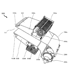
front perspective views of an exemplary blower pack element according to an
embodiment of the
invention such as depicted by blower pack element 200A in Figure 2. Referring
to image 500 in
Figure 5 the blower pack element is depicted in a rear perspective view
comprising upper fan
510A, first cover 520A, lower fan 510B, second cover 520B which form part of a
fan assembly
such as fan assembly 350 in Figure 3B. Also depicted are upper body portion
530A and lower
body portion 530B which form the mist channel 360. Also depicted within the
lower body
portion 530B are first to third inlets 210A to 210C. In image 600 of Figure 6
the blower pack
element is depicted in a rear perspective view comprising upper fan 510A,
first cover 520A,
lower fan 510B, second cover 520B, upper body portion 530A, lower body portion
530B,
pressurised box 610 together with the mist outlet 310.
100441 Figures 7 and 8 respectively depict images 700 and 800 presenting a
side view and cross-
sectional side elevation respectively of an exemplary blower pack element
according to an
embodiment of the invention such as depicted by blower pack element 200A in
Figure 2. As
depicted in images 700 and 800 the blower pack element comprises a first cover
520A and
second cover 520B which form part of a fan assembly such as fan assembly 350
in Figure 38
together with upper body portion 530A and lower body portion 530B which form
the mist
channel 360. The fan assembly 350 as depicted in image 700 also comprises a
first fan 510A and
- 9 -
CA 3049382 2019-07-09
a lower fan 510B. These comprise a motor and a blade assembly such that in
image 800 the first
fan 510A is now depicted by first blade 810A and second fan 510B is now
depicted by second
blade 810B.
[0045] Now referring to Figure 9 image 900 depicts a rear side cross-sectional
perspective view
of an exemplary blower pack according to an embodiment of the invention such
as depicted by
blower pack element 200A in Figure 2. Accordingly, image 900 depicts the mist
outlet 310
formed from the pressurised box 610 and mist channel, such as mist channel 360
in Figure 3B,
comprising upper body portion 530A and lower body portion 530B. The lower body
portion
530B also showing first and second inlets 220A and 220B respectively. Also
depicted are upper
cover 520A, lower cover 520B, first blade 810A, and second blade 810B. The
mist generated by
the humification element is coupled to the mist channel wherein the pressure
flow is coupled to
the mist outlet 310. This mist pressure flow as described above therefore
propagates through the
mist channel to the mist outlet 310. The first blade 810A of the upper fan
draws air through the
first cover 520A and directs it into upper pressurised chamber 920A of the
pressurised box 610
and pushes it through the upper outlet 910A. Similarly, the second blade 810B
of the lower fan
draws air through the second cover 520B and directs it into lower pressurised
chamber 920B of
the pressurised box 610 and pushes it through the lower outlet 910B. The air
flows from the
upper outlet 910A and lower outlet 910B therefore combine with the misted
pressure flow to
provide the humidified air flow from the humidification system comprising the
internal
humidification element and blower pack.
[0046] Referring to Figure 10 image 1000 depicts a side cross-sectional
perspective view of an
exemplary blower pack according to an embodiment of the invention such as
depicted in image
900 in Figure 9 without the blades of the upper and lower fans. Accordingly,
it is evident from
image 1000 that the upper outlet 910A has a larger exit area than the lower
outlet 910B. When
the upper and lower fans are providing the same air flow the lower exit area
of the lower outlet
910B relative to the upper exit area of the upper outlet 910A results in air
exiting the lower outlet
910B at higher velocity / lower pressure than that from the upper outlet 910B
such that the
"mist" is not lifted substantially. Now, considering the reverse of the
scenario above a lower
velocity / higher pressure of the air exiting the lower outlet 910B relative
to that of the upper
outlet 910B would "lift" the mist projecting it further. Accordingly, by
appropriate design of the
- 10 -
CA 3049382 2019-07-09
relative areas of the upper outlet 910A and lower outlet 910B for the same air
flow volumes the
mist flow from the mist channel can be distributed with different "throws."
Accordingly, the
effective dispersal distance of the mist can be adjusted through varying the
flow rate from the
lower outlet 910B relative to the upper outlet 910A.
100471 As depicted in Figure 10 with image 1000 the mist carrying airflow
exits the mist outlet
310 at a first angle, ai, relative to the horizontal. The airflow from the
upper outlet 910A in
contrast is directed by the upper outlet 910A itself and/or the louvres within
the exit portion of
the upper outlet 910A at a second angle, a2, relative to the horizontal. The
airflow from the
lower outlet 910B in contrast is directed by the lower outlet 910B itself
and/or the louvres within
the exit portion of the lower outlet 910B at a third angle, 13, relative to
the horizontal.
Accordingly, the airflows from the upper outlet 910A and lower outlet 910B
impinge each other
at a position in front of the mist outlet 310 established by the relative
angular offsets between the
airflow from these outlets at the second and third angles, a2 and a3
respectively, and the mist
flow at the first angle, al. Optionally, within embodiments of the invention
the relative angular
offsets of the second and third angles, a2 and a3 respectively, to the mist
flow at the first angle,
al, may be the same. Within other embodiments of the invention the relative
angular offsets of
second and third angles, a2 and a3 respectively, and the mist flow at the
first angle, al, may be
different such that the airflows from the upper outlet 910A and lower outlet
910B impinge the
mist flow from the mist outlet 310 at different positions. For example, these
relative angular
offsets may be between 00 and 50, between 5 and 10 , between 100 and 15 ,
between 15 and
20 , between 10 and 20 , between 15 and 25 .
[00481 The result of these airflows from the upper outlet 910A and lower
outlet 910B impinging
upon each other and upon the mist flow is to create turbulence which enhances
the absorption of
the mist from the mist outlet 310 into the airflows from the upper outlet 910A
and lower outlet
910B. This turbulence is important is establishing a relatively short
absorption distance, this
being the distance required to change the visible water vapour into an
invisible gas, in
combination with mixing the mist with a large volume of air.Now referring to
Figure 15 there is
depicted a cross-sectional plan elevation view in image 1500 of the
pressurized box 610 and mist
channel for an exemplary blower pack according to an embodiment of the
invention. As depicted
- 11 -
CA 3049382 2019-07-09
the lower body portion 530B in combination with upper body portion 520A, not
depicted for
clarity, provide the mist outlet 310 providing exit flow 1510. Within Figures
13 and 14 the upper
outlet 910A and lower outlet 910B from the pressurized box were described
which as noted
above merge to provide a turbulent region to aid in the mixing of the mist
with the air from the
blower pack. In Figure 15 there are depicted left side channel 1540 and right
side channel 1550
between the pressurized box 610 and the lower body portion 530B (as well as
with the upper
body portion 530A not depicted for clarity). These provide left flow 1520 and
right flow 1530
from the pressurized box which are substantially parallel to the exit flow
1520 at the mist outlet
310,
[00491 The inventors have established that the left flow 1520 and right flow
1530 reduce
recirculation of the mist at the mist outlet which would otherwise create
condensates on the side
walls of the mist outlet or further back into the mist channel and lead to the
potential for spitting
of these condensates from the system into the environment. The inventors
having further
established that if the airflow from each of the left flow 1520 and right flow
1530 are directed
inwards towards the mist then the absorption distance increases and there is
potential for the
condensates, e.g. droplets, to form on the inside of the mist channel side
walls. However, if the
airflow from each of the left flow 1520 and right flow 1530 are directed away
from the mist then
there is the potential for these condensates, e.g. droplets, to form on the
outside and front surface
of the mist channel side walls.
[00501 Within other embodiments of the invention the mist outlet, such as mist
outlet 310 in
Figure 3, may be filled with a structure to improve the air flow at the mist
outlet, such as
providing laminar flow for example. An example of such a structure being a
honeycomb.
[00511 Alternatively, for a given relative areas of the upper outlet 910A and
lower outlet 910B
the "throw" of the mist flow from the mist channel can be adjusted by
adjusting the air flow
volumes through the upper and lower pressurised chambers 920A and 920B
respectively. This
being accomplished by adjusting the relative speeds of the upper and lower
fans respectively.
[0052] It is also evident from Figure 10 that the lower and upper inner
surfaces of the mist
channel is orientated such that it slopes upwards from the first to third
inlets 210A to 210C
respectively to the mist outlet 310. Accordingly, any condensation onto these
results in the water
running back down towards the first to third inlets 210A to 210C respectively
and therefrom to
- 12 -
CA 3049382 2019-07-09
the internal humidification unit, such as internal humidification unit 200B in
Figure 2B. In this
manner, "spitting" of water droplets out from the blower pack element during
operation is
avoided.
[0053] Now referring to Figures 11 and 12 respectively there are depicted
cross-sectional side
elevation views of the pressurised box 610 and mist channel, such as mist
channel 360 in Figure
3B, for an exemplary blower pack according to an embodiment of the invention.
The pressurised
box 610 is depicted with first and second fan housings 1110A and 1110B
respectively in order to
show the fan feeds 1120A and 1120B between the first and second fan housings
1110A and
1110B respectively and pressurised box 610. The first and second fan housings
1110A and
1110B respectively forming part of the fan assembly, such as fan assembly 350
in Figure 3B. As
depicted the mist channel, such as mist channel 360 in Figure 3B, comprises an
upper body
portion 530A and lower body portion 530B.
[0054] Also referring to Figures 13 and 14 respectively there are depicted a
front and side cross-
sectional elevation views of the pressurised box 610 and mist channel, such as
mist channel 360
in Figure 3B, assembly for an exemplary blower pack according to an embodiment
of the
invention. Accordingly, there are depicted the pressurised box 610 surrounding
the mist channel,
such as mist channel 360 in Figure 3B, comprising upper body portion 530A and
lower body
portion 530B thereby forming the upper outlet 910A and lower outlet 910B for
the air from the
fan(s) within the blower pack element to flow out and mix with / carry the
mist from the mist
outlet 310.
[0055] It is evident from Figures 11 to 14 that the end portions of the
pressurised box forming
the upper and lower outlets 910A and 910B are shaped relative to the mist
channel in order to
direct their air flow towards the mist as it exits the mist channel. On the
lower side with the
smaller area this is provided by shaping the lower internal surface of the
pressurised box relative
to the mist channel and on the upper side with the larger area this is
provided by both shaping the
upper internal surface of the pressurised box and providing a louvre portion.
Within other
embodiments of the invention the shaping may be formed solely within the outer
surface(s) of
the mist channel or it may be formed by shaping of both the outer surface(s)
of the mist channel
and the inner surface(s) of the pressurised box.
- 13 -
CA 3049382 2019-07-09
[0056] Whilst the mist channel, such as mist channel 360 in Figure 3B has been
depicted and
presented as comprising an upper body portion 530A and lower body portion 530B
within other
embodiments of the invention it may be alternatively formed from a single
piece-part or multiple
piece parts according to the design, manufacturing and cost
constraints/requirements placed upon
the overall blower pack element etc. Similarly, whilst the pressurised box has
been described and
depicted as being a single piece part coupled to the fan assembly other
embodiments of the
invention the pressurised box may be formed from two or more piece parts again
according to
the design, manufacturing and cost constraints/requirements placed upon the
overall blower pack
element etc.
100571 Within the embodiments of the invention depicted the mist channel, such
as mist channel
360 in Figure 3B, has been described and depicted as comprising first to third
inlets 210A to
210C respectively which are coupled to the internal humidification element of
the humidifier
allowing the blower pack to support operation with an internal humidification
element providing
modular construction / assembly of units with different capacities. For
example, with three inlets
coupled to three ultrasonic mist chambers then the unit can be implemented
with one, two or
three ultrasonic generators providing configurability at three capacities. If
the ultrasonic
generators are employed in conjunction with a single water chamber with fully
implemented
ducting between the mist channel and reservoir with ultrasonic generators,
then any condensation
within the mist channel returns to the reservoir through the inlets. However,
if the design
provides multiple reservoirs then the humidification system may employ
different ducting to
route all the inlets back to the active reservoirs within the internal
humidification elements.
Alternatively, the mist channel may be designed with replaceable sections at
the rear distal to the
mist outlet such that only the required number of inlets are provided, and
blank panels are
employed for the remainder such that all condensation routes onto to the
active inlets. This
thereby avoiding potential for water to accumulate within inactive ducts /
ultrasound generators
etc.
[0058] Within the embodiments of the invention depicted the mist channel, such
as mist channel
360 in Figure 3B, has been described and depicted as being a single open
channel from the
inlet(s) to the outlet. However, within other embodiments of the invention the
mist channel may
comprise internal dividers, such as for example, to direct mist flow from the
inlets individually
- 14 -
CA 3049382 2019-07-09
before being combined within the mist channel or at/after the mist outlet.
Optionally, within
other embodiments of the invention multiple discrete mist channels may be
employed with a
single common pressurised box wherein the multiple mist channels are combined
at the mist
outlet or prior to the mist outlet. Optionally, within other embodiments of
the invention multiple
discrete mist channels may be employed with multiple pressurised boxes which
are coupled to a
common fan assembly such that the multiple mist channels are coupled to the
same fan(s).
Optionally, within other embodiments of the invention multiple discrete mist
channels may be
employed with multiple pressurised boxes which are coupled to multiple fan
assemblies such
that each mist channel / pressurised box combination is coupled to a different
fan(s) than the
other mist channel / pressurised box combinations.
10059] The foregoing disclosure of the exemplary embodiments of the present
invention has
been presented for purposes of illustration and description. It is not
intended to be exhaustive or
to limit the invention to the precise forms disclosed. Many variations and
modifications of the
embodiments described herein will be apparent to one of ordinary skill in the
art in light of the
above disclosure. The scope of the invention is to be defined only by the
claims appended hereto,
and by their equivalents.
[0060] Within the description above in respect of Figures IA to 15 the
pressurised box has
openings to the sides of the mist channel as well as above and below the mist
channel. Within
other embodiments of the invention these side openings may be omitted, have
different relative
areas to the upper / lower openings, and have different relative areas to each
other.
[0061] Within the description above in respect of Figures 1A to 15 the mist
channel and
pressurised box are presented as having an aspect ratio wherein relative to a
horizontal plane the
width is larger than the height. However, other embodiments of the invention
the aspect ratio
may be larger than that depicted/described, lower than that
described/depicted, and have larger
height than width.
[0062] Within the description above in respect of Figures IA to 15 the mist
channel and
pressurised box are presented as having an overall essentially rectangular
cross-section towards
the mist outlet where the pressurised box surrounds the mist channel. However,
it would be
evident that within other embodiments of the invention the geometry of the
pressurised box and
mist channel may be square, circular, elliptical, polygon, or defined by a
mathematical function
- 15 -
CA 3049382 2019-07-09
etc. Optionally, the geometry of the pressurised box and mist channel may be
the same or
different.
[0063] Whilst within embodiments of the invention the pressurised box of the
blower pack has
been described and depicted as employing one or more fans to generate the
airflow for
combining with the mist flow it would be evident that within other embodiments
of the invention
that the fan(s) may be replaced with another element(s) generating a flow
including, but not
limited to, a compressor and an outlet of a tank of liquefied gas (e.g.
nitrogen) or a subliming
material (e.g. carbon dioxide, also known as dry ice). Such systems may
support sporadic and/or
one off use rather than continuous or pseudo-continuous use. Further, the
description above in
respect of Figures 1A to 14 presumes the same gas is employed in the upper and
lower portions
of the pressurised box whilst these may be different in other embodiments of
the invention.
Further, the gas may be cooled and/or heated prior to coupling to the
pressurised box.
[00641 Within the description above in respect of Figures IA to 15 the
embodiments of the
invention have been described with respect to mist humidification systems
wherein a liquid, e.g.
water, is dispersed is mist form within an environment by initially
transporting the mist with a
first gas, e.g. air, and then combining this liquid / first gas with a second
gas, e.g. air, to project
or "throw" the mist into the environment. Accordingly, it would be evident
that within other
embodiments of the invention that other liquids may be dispersed into an
environment in mist
form either discretely or in conjunction with another liquid forming part of
the mist. It would be
further evident that within other embodiments of the invention that the first
gas / second gas may
be other than air.
[0065] Further, in describing representative embodiments of the present
invention, the
specification may have presented the method and/or process of the present
invention as a
particular sequence of steps. However, to the extent that the method or
process does not rely on
the particular order of steps set forth herein, the method or process should
not be limited to the
particular sequence of steps described. As one of ordinary skill in the art
would appreciate, other
sequences of steps may be possible. Therefore, the particular order of the
steps set forth in the
specification should not be construed as limitations on the claims. In
addition, the claims directed
to the method and/or process of the present invention should not be limited to
the performance of
- 16 -
CA 3049382 2019-07-09
their steps in the order written, and one skilled in the art can readily
appreciate that the sequences
may be varied and still remain within the spirit and scope of the present
invention.
- 17 -
CA 3049382 2019-07-09