Note: Descriptions are shown in the official language in which they were submitted.
CA 03049409 2019-07-04
WO 2018/129359 PCT/US2018/012642
Patent Application for
ELECTRICAL WIRING DEVICES WITH
SCREWLESS CONNECTION TERMINALS
CROSS REFERENCE TO RELATED APPLICATIONS
[0001] The present application is based on and claims benefit from co-pending
U.S.
Provisional Application Serial No. 62/443,020 filed January 6, 2017 entitled
"Electrical Wiring
Devices with Screwless Connection Terminals" the entire contents of which are
incorporated
herein in its entirety by reference.
BACKGROUND
Field
[0002] The present disclosure relates generally to connection terminals for
electrical wiring
devices and more particularly to screwless connection terminals for use in
receptacles, plug
assemblies, plug connectors, switches, and other electrical wiring devices.
Description of the Related Art
[0003] Present electrical wire terminations in many electrical wiring devices
are either direct
pressure type terminations or screw and clamp type terminations. In direct
pressure type
terminations, a terminal screw is tightened directly against an electrical
wire to press the wire
against a fixed plate. In screw and clamp type terminations, a wire is
inserted between a fixed
plate and a movable plate, and a terminal screw is tightened so that the wire
is clamped between
the plates. With direct pressure type terminations, stranded or solid wires if
incorrectly installed
can be cut or nicked. Cut or nicked wires can result in poor electrical
connections increasing the
resistance in the connections which can cause overheating. In addition, with
stranded wires, both
1
CA 03049409 2019-07-04
WO 2018/129359 PCT/US2018/012642
direct pressure type terminations and screw and clamp type terminations may be
susceptible to
strand relaxation. Strand relaxation is a result of copper wire heating and
cooling under the
stress of the termination, either direct pressure type or screw and clamp type
causing the
electrical connection between the stranded wire and the termination to loosen
increasing the
resistance in the connections which can cause overheating. To alleviate strand
relaxation
concerns, installers typically re-torque terminal screws after some duration
of time after original
installation increasing costs to consumers.
SUMMARY
[0004] The present disclosure provides embodiments of various electrical
wiring devices,
including receptacles, power cord plugs and connectors, and switches. In an
exemplary
embodiment, a blade-type electrical receptacle includes a housing and a
plurality of contact
assemblies. The housing has a main body with a plurality of cavities, a front
cover and a rear
cover. The front cover is removably secured to a first side of the main body
and includes a
plurality of blade receiving slots. The rear cover is removably secured to a
second side of the
main body and includes a plurality of wire receiving apertures and a plurality
of plunger
openings.
[0005] In one exemplary embodiment, one of the plurality of contact assemblies
is positioned
at least partially within one of the plurality of cavities and is accessible
from one of the plurality
of wire receiving apertures, from one of the plurality of plunger openings in
the rear cover, and is
accessible from one of the plurality of blade receiving slots in the front
cover. Each of the
plurality of the contact assemblies includes a contact member, a wire terminal
and a plunger. In
an exemplary embodiment, the contact member has a contact body and at least
two contact
fingers extending from the contact body. The at least two contact fingers are
aligned with one of
the plurality of blade receiving slots in the front cover. The wire terminal
forms an electrically
conductive path with the contact member, and includes a contact arm secured to
the contact
body, a clamp brace secured to the contact arm and a clamp spring secured to
the clamp brace.
2
CA 03049409 2019-07-04
WO 2018/129359 PCT/US2018/012642
The clamp spring is movable relative to the clamp brace between a closed
position where a wire
can be clamped between the clamp spring and the clamp brace and an open
position where a wire
can be inserted through one of the plurality of wire receiving apertures in
the rear cover and
between the clamp spring and the clamp brace. The plunger is positioned within
one of the
plurality of cavities and extends at least partially through one of the
plurality of plunger openings
in the rear cover. The plunger is interactive with the clamp spring such that
movement of the
plunger in a first direction relative to the clamp brace causes the plunger to
apply a mechanical
load to the clamp spring to cause the clamp spring to move from the closed
position to the open
position, and movement of the plunger in a second direction relative to the
clamp brace removes
the mechanical load from the clamp spring so that to the clamp spring is
biased from the open
position to the closed position.
[0006] The present disclosure also provides embodiments of blade type
electrical power cord
connectors. In an exemplary embodiment, a blade-type electrical power cord
connector includes
a housing and a plurality of contact assemblies. The housing includes a main
body, a cover and a
retainer. The main body has a plurality of cavities and a plurality of blade
receiving slots. The
cover is removably secured to the main body and has a cable receiving
aperture. The retainer is
removably secured to the main body between the main body and the cover and has
a plurality of
wire receiving apertures and a plurality of plunger openings.
[0007] In one exemplary embodiment, one of the plurality of contact assemblies
is positioned
at least partially within one of the plurality of a cavities and is accessible
from one of the
plurality of wire receiving apertures, from one of the plurality of plunger
openings in the
retainer, and is accessible from one of the plurality of blade receiving slots
in the main body.
Each of the plurality of the contact assemblies includes a contact member, a
wire terminal and a
plunger. In an exemplary embodiment, the contact member has a contact body and
at least two
contact fingers extending from the contact body. The at least two contact
fingers are aligned
with one of the plurality of blade receiving slots in the main body of the
housing. The wire
terminal forms an electrically conductive path with the contact member, and
includes a clamp
brace secured to the contact body and a clamp spring secured to the clamp
brace. The clamp
3
CA 03049409 2019-07-04
WO 2018/129359 PCT/US2018/012642
spring is movable relative to the clamp brace between a closed position where
a wire can be
clamped between the clamp spring and the clamp brace and an open position
where a wire can be
inserted through one of the plurality of wire receiving apertures in the
retainer and between the
clamp spring and the clamp brace. The plunger is positioned within one of the
plurality of
cavities and extends at least partially through one of the plurality of
plunger openings in the
retainer. The plunger is interactive with the clamp spring such that movement
of the plunger in a
first direction relative to the clamp brace causes the plunger to apply a
mechanical load to the
clamp spring to cause the clamp spring to move from the closed position to the
open position,
and movement of the plunger in a second direction relative to the clamp brace
removes the
mechanical load from the clamp spring so that to the clamp spring is biased
from the open
position to the closed position.
[0008] The present disclosure also provides embodiments of blade type
electrical power cord
plugs. In an exemplary embodiment, a blade-type electrical power cord plug
includes a housing
and a plurality of contact assemblies. The housing includes a main body, a
bottom cover, a top
cover and a retainer. The main body has a plurality of cavities. The bottom
cover is removably
secured to a first side of the main body and has a plurality of blade
receiving slots. The top
cover is removably secured to a second side of the main body and has a cable
receiving aperture.
The retainer is removably secured to the second side of the main body between
the main body
and the top cover and has a plurality of wire receiving apertures and a
plurality of plunger
openings.
[0009] In one exemplary embodiment, one of the plurality of contact assemblies
is positioned
at least partially within one of the plurality of a cavities and is accessible
from one of the
plurality of wire receiving apertures, from one of the plurality of plunger
openings in the
retainer, and is accessible from one of the plurality of blade receiving slots
in the bottom cover.
In an exemplary embodiment, the each of the plurality of the contact
assemblies includes a
contact member, a wire terminal and a plunger. The contact member has a
contact body and a
contact blade extending from the contact body. The contact blade is aligned
with one of the
plurality of blade receiving slots in the bottom cover such that the blade can
pass through the
4
CA 03049409 2019-07-04
WO 2018/129359 PCT/US2018/012642
blade receiving slot and extend from the housing. The wire terminal forms an
electrically
conductive path with the contact member, and includes a clamp brace secured to
the contact
body and a clamp spring secured to the clamp brace. The clamp spring is
movable relative to the
clamp brace between a closed position where a wire can be clamped between the
clamp spring
and the clamp brace and an open position where a wire can be inserted through
one of the
plurality of wire receiving apertures in the retainer and between the clamp
spring and the clamp
brace. The plunger is positioned within one of the plurality of cavities and
extends at least
partially through one of the plurality of plunger openings in the retainer.
The plunger is
interactive with the clamp spring such that movement of the plunger in a first
direction relative to
the clamp brace causes the plunger to apply a mechanical load to the clamp
spring to cause the
clamp spring to move from the closed position to the open position, and
movement of the
plunger in a second direction relative to the clamp brace removes the
mechanical load from the
clamp spring so that to the clamp spring is biased from the open position to
the closed position.
[0010] The present disclosure also provides embodiments of electrical wiring
device for
installation into an electrical box. In an exemplary embodiment, the
electrical wiring device
includes a housing and a plurality of contact assemblies. The housing includes
a main body
portion having a plurality of cavities, a front cover portion removably
secured to a first side of
the main body portion, and a rear cover portion removably secured to a second
side of the main
body portion and having a plurality of wire receiving apertures and a
plurality of plunger
openings. In this embodiment, one of the plurality of contact assemblies is
positioned at least
partially within one of the plurality of a cavities and is accessible from one
of the plurality of
wire receiving apertures and one of the plurality of plunger openings in the
rear cover portion.
Each of the plurality of the contact assemblies includes a wire terminal and a
plunger. The wire
terminal includes a clamp brace secured to a clamp spring. The clamp spring is
movable relative
to the clamp brace between a closed position where a wire can be clamped
between the clamp
spring and the clamp brace, and an open position where a wire can be inserted
through one of the
plurality of wire receiving apertures in the rear cover and between the clamp
spring and the
clamp brace. The plunger is positioned within one of the plurality of cavities
and extends at least
CA 03049409 2019-07-04
WO 2018/129359 PCT/US2018/012642
partially through one of the plurality of plunger openings in the rear cover.
The plunger is
interactive with the clamp spring such that movement of the plunger in a first
direction relative to
the clamp brace causes the plunger to apply a mechanical load to the clamp
spring to cause the
clamp spring to move from the closed position to the open position and
movement of the plunger
in a second direction relative to the clamp brace removes the mechanical load
from the clamp
spring so that to the clamp spring is biased from the open position to the
closed position.
BRIEF DESCRIPTION OF THE DRAWINGS
[0011] A more complete appreciation of the present disclosure and many of the
attendant
advantages thereof will be readily obtained as the same becomes better
understood by reference
to the following detailed description when considered in connection with the
accompanying
drawings, wherein:
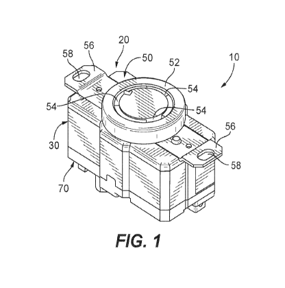
[0012] Fig. 1 is a top perspective view of an exemplary embodiment of an
electrical receptacle
having screwless connection terminals according to the present disclosure;
100131 Fig. 2 is a bottom perspective view of the receptacle of Fig. 1;
100141 Fig. 3 is a bottom plan view of the receptacle of Fig. 1;
100151 Fig. 4 is a cross sectional view of the receptacle of Fig. 3 taken
along line 4-4;
[001.6] Fig. 5 is a cross sectional view of the receptacle of Fig. 3 taken
along line 5-5;
[0017] Fig. 6 is a top perspective view of a rear cover of the receptacle
housing of Fig. 1 with
three contact assemblies resting on the rear cover;
100181 Fig. 7 is a bottom perspective view of a housing of the receptacle of
Fig. 1 having three
cavities each housing a contact assembly;
[001.9] Fig. 8 is a top perspective view of an exemplary embodiment of a
screwless connection
terminal for the receptacle of Fig. 1 in a closed position;
6
CA 03049409 2019-07-04
WO 2018/129359 PCT/US2018/012642
[0020] Fig. 9 is a top perspective view of the screwless connection terminal
of Fig. 8 in an
open position;
[0021] Fig. 10 is a side elevation view of an exemplary embodiment of an
electrical power
cord connector having the screwless connection terminals according to the
present disclosure;
[0022] Fig. 11 is a bottom plan view of the cord connector of Fig. 10;
[0023] Fig. 12 is a side perspective view with parts separated of the cord
connector of Fig. 10;
[0024] Fig. 13 is a top perspective view of a portion of the cord connector of
Fig. 12,
illustrating a plurality of contact assemblies within a housing of the cord
connector;
[0025] Fig. 14 is a top perspective view of the portion of the cord connector
of Fig. 12 with a
retainer secured to a main body of the housing;
[0026] Fig. 15 is a top perspective view of an exemplary embodiment of a
screwless
connection terminal for the cord connector of Fig. 10 in a closed position;
[0027] Fig. 16 is a top perspective view of the screwless connection terminal
of Fig. 15 in an
open position;
[0028] Fig. 17 is a side elevation view of an exemplary embodiment of an
electrical power
cord plug having the screwless connection terminals according to the present
disclosure;
[0029] Fig. 18 is a side perspective view with parts separated of the cord
plug of Fig. 17;
[0030] Fig. 19 is a top perspective view of a portion of the cord plug of Fig.
18, illustrating a
plurality of contact assemblies in a main body of a housing of the cord plug;
[0031] Fig. 20 is a top perspective view of the portion of the cord plug of
Fig. 18 with a
retainer secured to the main body of the cord plug housing;
[0032] Fig. 21 is a top perspective view of an exemplary embodiment of a
screwless
connection terminal for the cord plug of Fig. 17 in a closed position;
7
CA 03049409 2019-07-04
WO 2018/129359 PCT/US2018/012642
100331 Fig. 22 is a top perspective view of the screwless connection terminal
of Fig. 21 in an
open position;
[0034] Fig. 23 is a top perspective view if another exemplary embodiment of an
electrical
receptacle having screwless connection terminals according to the present
disclosure;
100351 Fig. 24 is a bottom perspective view of the receptacle of Fig. 23;
100361 Fig. 25 is a bottom plan view of the receptacle of Fig. 24;
100371 Fig. 26 is a cross sectional view of the receptacle of Fig. 25 taken
along line 26-26;
100381 Fig. 27 is a top perspective view if an exemplary embodiment of an
electrical switch
having screwless connection terminals according to the present disclosure;
[0039] Fig. 28 is a bottom perspective view of the switch of Fig. 27;
[0040] Fig. 29 is a bottom plan view of the switch of Fig. 28;
[0041] Fig. 30 is a cross sectional view of the switch of Fig. 29 taken along
line 30-30;
[0042] Fig. 31 is a top perspective view of another exemplary embodiment of a
screwless
connection terminal for the electrical switch of Fig. 27 in a closed position;
and
100431 Fig. 32 is a top perspective view of the screwless connection terminal
of Fig. 31 in an
open position.
DETAILED DESCRIPTION
[0044] Exemplary embodiments of electrical wiring devices that incorporate the
screwless or
clamp wire terminal of the present disclosure are shown and described. Non-
limiting examples
of the electrical wiring devices contemplated by the present disclosure
include, single and duplex
blade-type electrical receptacles, blade-type locking electrical receptacles,
single or multi-pole
electrical switches, combination switches and blade-type receptacles, blade-
type plugs for
8
CA 03049409 2019-07-04
WO 2018/129359 PCT/US2018/012642
electrical cords and blade-type connectors for electrical cords. Blade-type
electrical wiring
devices as described herein are; a) male blade-type electrical wiring devices
with a plurality of
non-circular, e.g., substantially flat or arcuate, power contact blades (hot
and/or neutral contact
blades) that can mate with corresponding finger contacts within a female blade-
type electrical
wiring device, or b) female blade-type electrical wiring devices with a
plurality of non-circular,
e.g., substantially flat or arcuate, power contact blade apertures (hot and/or
neutral contact blade
apertures) that provide access to contact fingers within the female electrical
wiring devices that
can mate with corresponding non-circular power contact blades of male blade-
type electrical
wiring devices. Examples of blade-type electrical wiring devices are described
in NEMA
standard WD6, which is publicly available and incorporated herein in its
entirety by reference.
In one exemplary embodiment, a blade-type electrical receptacle includes a
housing and a
plurality of female contact assemblies within the housing that are accessible
from an exterior of
the housing. In another exemplary embodiment, a blade-type electrical power
cord connector
includes a housing and a plurality of female contact assemblies within the
housing that are
accessible from an exterior of the housing and capable of receiving a
plurality of blades of a
plug. In another exemplary embodiment, a blade-type electrical power cord plug
includes a
housing and a plurality of male contact assemblies within the housing that
extend beyond an
exterior of the housing.
[0045] In some embodiments, the housing has a front cover and a main body. In
other
embodiments, the housing has a front cover, a main body and a rear cover. In
each embodiment
of an electrical wiring device, each contact assembly has a contact member, a
wire terminal and a
plunger. The contact member is used to form a portion of a conductive
electrical path. The wire
terminal is used to terminate an electrical conductor inserted into the
housing, and the plunger
moves the wire terminal between open and closed positions. The wire terminal
includes a clamp
brace, a contact arm and a clamp spring. The contact arm connects the wire
terminal to the
contact member, and the clamp spring is used to apply a constant and
continuous load (or spring
force) against an electrical conductor to electrically connect the electrical
conductor to the clamp
brace. The plunger is used to move the clamp spring between the open position
permitting an
9
CA 03049409 2019-07-04
WO 2018/129359 PCT/US2018/012642
electrical conductor to enter the wire terminal and the closed position
binding or squeezing the
electrical conductor within the wire terminal.
[0046] For the purposes of the present disclosure, the electrical conductor
may also be referred
to as the "wire." Further, the electrical conductor can be any size wire used
to conduct
electricity, such as 1.4 AWG wire, 12 AWG wire, 10 AWG wire or 8 .AWG wire.
Depending
upon the number of conductors in a power cord, generally, 14 AWG wires are
rated for between
15 and 18 amps, 12 AWG wires are rated for between 20 and 25 amps, 10 AWG
wires are rated
for between 25 and 30 amps, and 8 AWG wires are rated for between 35 and 40
amps.
[0047] Referring now to Figs. 1-9, an exemplary embodiment of a locking blade
type electrical
receptacle is shown. In this exemplary embodiment, the receptacle 10 has a
housing 20 and a
plurality of contact assemblies 100, seen in detail in Figs. 8 and 9, within
the housing that are
accessible from an exterior of the housing. The housing 20 has a main body 30,
a front cover 50
and a rear cover 70. The front cover 50 is secured to one side of the main
body 30 and the rear
cover 70 is secured to the other side of the main body. The housing 20 is made
of a suitable
electrical insulating material, such as plastic, including injection molded
thermoplastic, and is
configured to fit within an electrical box.
[0048] The main body 30 includes a plurality of chambers or cavities 32, seen
in Figs. 4 and 5.
Each cavity 32 is configured to receive and position a contact assembly 100
within the main
body 30, as shown in Figs. 6 and 7. Each contact assembly 100 is configured to
receive a wire,
such as wire 700 shown in Fig. 5, and to mate with a contact blade of a plug
connector, such as
the plug connector of Fig. 17.
[0049] As shown in Fig. 1, the front cover 50 of the receptacle 10 includes a
face 52 having a
plurality of blade-receiving slots 54 through which contact blades of a plug
connector, such as
the contact blades of the plug connector shown in Fig. 17, can be inserted in
the usual manner
into adjacent cavities 32 within the main body 30. The front cover 50 has one
or more mounting
straps 56 that are secured to an exterior surface of the front cover using,
for example, mechanical
fasteners or adhesives. The mounting straps 56 are used to secure the
receptacle 10 to an
CA 03049409 2019-07-04
WO 2018/129359 PCT/US2018/012642
electrical box via apertures 58 as is known. The mounting straps 56 may also
be connected to
electrical ground via a contact assembly 100 within the main body 30. The
front cover 50 can be
secured to the main body 30 using mechanical fasteners, adhesives or welds
such as sonic welds.
100501 Referring to Figs. 2, 3 and 5, the rear cover 70 can be secured to the
main body 30
using mechanical fasteners, such as screws 72, adhesives or welds such as
sonic welds. The rear
cover 70 includes a plurality of wire receiving apertures 74. Each wire
receiving aperture 74 is
positioned to align with a cavity 32 in the main body 30 so that a wire can
pass through the rear
cover 70 into a contact assembly 100 resting within a cavity 32 in the main
body 30. The rear
cover 70 may also include a plurality of wire guides 76 extending outwardly
from an exterior
surface 78 of the rear cover, as shown. In the embodiment shown, one wire
guide 76
corresponds to one wire receiving aperture 74. Each wire guide 76 has an
arcuate shape that
corresponds to the round shape of a wire being inserted into the wire
receiving aperture 74. The
rear cover 70 also includes a plurality of plunger openings 80, seen in Figs.
2 and 3, that permits
a portion of a plunger 150, forming a portion of the contact assembly 100
described below, to
extend outside the housing 20.
[0051] Turning to Figs. 8 and 9, an exemplary embodiment of a contact assembly
100
according to the present disclosure is shown. In this exemplary embodiment,
the contact
assembly 100 includes a contact member 110, a wire terminal 130 and a plunger
150. The
contact member 110 is made of an electrically conductive material, such as
brass, copper or
aluminum. The wire terminal 130 is made of an electrically conductive
resilient material with
sufficient stiffness to flex when a mechanical load is applied and return to
its normal position
when the mechanical load is removed. An example of such an electrically
conductive resilient
material is spring steel. The plunger 150 is made of a suitable rigid
electrical insulating material,
such as plastic materials. An example of a plastic material is injection
molded thermoplastic.
The contact member 110 and the wire terminal 130 can be formed as a unitary
structure, or the
contact member and wire terminal can be individual components secured together
by, for
example, a solder joint, a brazed joint, or a welded joint.
11
CA 03049409 2019-07-04
WO 2018/129359 PCT/US2018/012642
[0052] The contact member 110 includes a contact body 112 and a pair of
flexible fingers 114
and 116 extending from the contact body 112, as shown. The flexible fingers
114 and 116 form
a female contact configured to engage a contact blade of a blade-type
electrical power cord plug,
such as a contact blade of the plug shown in Fig. 17. The distal ends of the
flexible fingers 114
and 116 contact each other or are in close proximity to each other to form a
gripping portion 118
between the fingers. The gripping portion 118 is capable of receiving a
contact blade so as to
electrically couple or connect the contact member 110 to the contact blade.
Thus, each contact
assembly 100 is adapted to engage one of a plurality of contact blades of a
blade-type electrical
power cord plug.
[0053] The wire terminal 130 is a mechanical clamping terminal that uses one
or more springs
that can deflect under a mechanical load applied by the plunger 150 and
recover to their initial
shape when the mechanical load is removed. The energy stored by the one or
more springs
should be sufficient to apply a constant and continuous force to mechanically
secure one or more
wires, e.g., wire 700 shown in Fig. 5, to the wire terminal 130.
[0054] In the exemplary configuration shown in Figs. 8 and 9, the wire
terminal 130 includes a
clamp brace 132, a contact arm 134 and a clamp spring 136. The clamp brace 132
is a fixed
terminal body that may be a substantially planar shaped member or an arcuate
shaped member
secured to the contact body 112 of the contact member 110 via the contact arm
134. The contact
arm 134 also provides an electrically conductive path between the contact
member 110 and the
wire terminal 130. The clamp spring 136 includes an end portion 138, a spring
member 140 and
a clamp arm 142. The end portion 138 can be a substantially planar shaped
member or an
arcuate shaped member that is configured to mate with the clamp brace 132 and
is secured to the
clamp brace by, for example, a solder joint, a brazed joint, or a welded
joint. The spring member
140 has a lower lobe 140a and an upper lobe 140b. The lower lobe 140a and the
upper lobe
140b are configured to interact with the plunger 150 so that vertical movement
of the plunger
relative to the spring member 140 is translated to the application of a
mechanical load on the
spring member 140 or the removal of the mechanical load on the spring member.
For example,
the plunger 150 can be a rectangular shaped member having a notch 152 that is
configured to
12
CA 03049409 2019-07-04
WO 2018/129359 PCT/US2018/012642
receive the upper lobe 140b of the spring member 140, as shown in Fig. 8. The
notch 152 has a
camming surface 152a that rides along the spring member 140 when the plunger
150 is moved in
the direction of arrow "B" applying a mechanical load on the spring member 140
causing the
spring member to deflect in the direction of arrow "C" toward the open
position, seen in Fig. 9.
The clamp arm 142 extends from the upper lobe 140b of the spring member 140
toward the
clamp brace 132, as shown. The clamp arm 142 has an elongated opening 144
configured to
receive a portion of the clamp brace 132 and a clamp member 146 that contacts
a wire, e.g., wire
700 seen in Fig. 5, positioned between the clamp brace and the clamp member
when the clamp
spring 136 is in the closed position. The clamp arm 142 is movable relative to
the clamp brace
132 between the closed position, seen in Fig. 8, and the open position, seen
in Fig. 9.
[0055] As noted, the wire terminal 130 can connect to electrical conductors of
different sizes.
For example, if the blade-type electrical receptacle 10 is rated for 15 amps,
then the wire
terminal 130 should also be configured and rated for at least 15 amps. The
wire size, i.e., the
bare conductor size, for 15 amps is 14 AWG wire such that the clamp arm 142
should be able to
move to an open position where the outer diameter of 14 AWG wire can fit. As
another
example, if the blade-type electrical receptacle is rated for 20 amps, then
the wire terminal 130
should also be rated for at least 20 amps. The wire size, i.e., the bare
conductor size, for 20 amps
is 12 AWG wire such that the clamp arm 142 should be able to move to an open
position where
the outer diameter of 12 AWG wire can fit. As another example, if the blade-
type electrical
receptacle is rated for 30 amps, then the wire terminal 130 should also be
rated for at least 30
amps. The wire size, i.e., the bare conductor size, for 30 amps is 10 AWG wire
such that the
clamp arm 142 should be able to move to an open position where the outer
diameter of 10 AWG
wire can fit. As another example, if the blade-type electrical receptacle is
rated for 40 amps, then
the wire terminal 130 should also be rated for at least 40 amps. The wire
size, i.e., the bare
conductor size, for 40 amps is 8 AWG wire such that the clamp arm 142 should
be able to move
to an open position where the outer diameter of 8 AWG wire can fit.
[0056] As noted, the spring member 140 is made of an electrically conductive
resilient
material with sufficient stiffness to flex when the plunger 150 pushes the
spring member 140
13
CA 03049409 2019-07-04
WO 2018/129359 PCT/US2018/012642
from the closed position to the open position while applying a biasing force
(i.e., a spring force)
through the clamp member 146 to a wire between the clamp member and the clamp
brace 132.
As an example, the spring arm 140 can be made of metal, such as spring steel.
The biasing force
(or spring force) exerted by the spring arm 140 clamping a wire between the
clamp member 146
and the clamp brace 132 should be sufficient to apply a constant and
continuous force on the
wire to electrically couple or connect the wire terminal 130 to the wire in
various temperature
and environmental conditions. The spring member 140 is configured so that it
is normally biased
toward the closed position, i.e., in the direction of arrow "A" which is away
from the clamp
brace 132, as seen in Fig. 8. In the spring member's normal position without a
conductor
inserted into the elongated opening 144, the clamp member 146 of the clamp arm
142 can
contact the clamp brace 132.
[0057] As described herein, the receptacle 10 uses contact assemblies 100 to
terminate
electrical conductors or wires within an electrical box. To connect wires
within an electrical box
to the receptacle 10, an installer, e.g., an electrician, strips the
insulation from the end of each
wire. In this exemplary embodiment, the receptacle 10 has three contact
assemblies 100 such
that three wires can be connected to the receptacle. However, it is also
contemplated that each
contact assembly could be configured to electrically connect more than one
wire to the contact
assembly 100. The plungers 150 for each contact assembly 100 extending through
the rear cover
70 are then pulled vertically relative to a longitudinal axis of the
receptacle 10, i.e., in the
direction of arrow "B" seen in Fig. 8, to cause the camming surface 152a of
the notch 152 in the
plunger 150 to ride along the spring member 140 applying a mechanical load on
the spring
member 140 causing the spring member to deflect in the direction of arrow "C"
from the closed
position toward the open position, seen in Fig. 9. With the wire terminals 130
in the open
position, the electrical wires are then inserted into the appropriate wire
receiving aperture 74 in
the rear cover 70 of the receptacle 10. The wire receiving apertures 74 and
wire guides 76 guide
the bare end of the wires into the portion of the elongated opening 144 of the
clamp spring 136
between clamp brace 132 and clamp member 146. When the bare end of each wire
is positioned
between the clamp brace 132 and the clamp member 146, the respective plunger
150 is then
14
CA 03049409 2019-07-04
WO 2018/129359 PCT/US2018/012642
pushed back into the receptacle 10 removing the mechanical load applied by the
plunger on the
spring member 140 so that the energy stored by the spring member moves the
spring member to
the closed position securing or clamping the wire between the clamp brace 132
and the clamp
member 146 completing an electrically conductive path between the wire and the
contact
member 110.
[0058] To remove the wires from the contact assembly 100, the plungers 150 for
each contact
assembly 100 extending through the rear cover 70 are pulled vertically
relative to a longitudinal
axis of the receptacle 10 to cause the camming surface 152a of the notch 152
in the plunger 150
to ride along the spring member 140 applying a mechanical load on the spring
member 140
causing the spring member to deflect from the closed position to the open
position. With the
wire terminals 130 in the open position, the electrical wires can be removed
from the receptacle.
[0059] Referring now to Figs. 10-16, an exemplary embodiment of a blade-type
electrical
power cord connector is shown. In this exemplary embodiment, the blade-type
connector 200
has a housing 210 and a plurality of contact assemblies 300 within the housing
that are accessible
from an exterior of the housing. The housing 210 has a main body 220, a
retainer 240 and a
cover 260. The retainer 240 is secured to a top side of the main body 220
using screw 242. The
cover 260 is secured to the top side of the main body using screws 222
inserted through apertures
in a face 224 in the main body 220 and through the main body. The housing 210
is made of a
suitably rigid, electrical insulating material, such as a plastic material,
including injection molded
thermoplastic, or a rubber material.
[0060] The main body 220 includes a plurality of chambers or cavities 226 seen
in Figs. 12 and
13. Each cavity 226 is configured to receive and position a contact assembly
300 within the
main body 220. Each contact assembly 300 is configured to receive a conductor
and to mate
with a contact blade of a blade-type plug connector, such as a contact blade
of the plug connector
of Fig. 17. The face 224 of the main body 220 has a plurality of blade-
receiving slots 228
through which contact blades of a blade-type plug connector can be inserted in
the usual manner
into adjacent cavities 226 within the main body 220 and into a respective
contact assembly 300.
CA 03049409 2019-07-04
WO 2018/129359 PCT/US2018/012642
100611 The cover 260 of the connector 200 may be hollow, partially hollow or
solid. As
shown in Figs. 10 and 12, the cover 260 includes a cable connector 262 at a
top portion of the
cover 260. The cable connector 262 includes a fixed bracket 264 and a movable
bracket 266
releasably secured to the fixed bracket using screws 268. In a central portion
of the connector
262 is a cable receiving opening 270 that extends through the cover 260. The
cable receiving
opening 270 permits an electrical power cord (not shown) to pass through the
cover 260 so that
electrical wires within the electrical power cord can be connected to the
contact assemblies 300.
[0062] Referring to Figs. 12 and 14, the retainer 240 is secured to the main
body 220 using
mechanical fasteners, such as screw 242. The retainer 240 includes a plurality
of wire receiving
apertures 244. Each wire receiving aperture 244 is positioned to align with a
cavity 226 in the
main body 220 so that a wire can pass through the retainer 240 into a contact
assembly 300
resting within a cavity 226 in the main body 220. The retainer 240 may also
include a plurality
of wire guides 246 extending outwardly from surface 248 of the retainer, as
shown. In the
embodiment shown, one wire guide 246 corresponds to one wire receiving
aperture 244. Each
wire guide 246 may have an arcuate like shape that corresponds to the shape of
a wire being
inserted into the wire receiving aperture 244. The retainer 240 also includes
a plurality of
plunger openings 250, seen in Fig. 14. In the embodiment shown, one plunger
opening 250
corresponds to one wire receiving aperture 244. The plunger openings 250
permit a portion of a
respective plunger 350 forming a portion of the contact assembly 300,
described below, to
extend outside the main body 2211 The retainer 240 may also include a
plurality of plunger
guides 254 extending outwardly from surface 252 of the retainer, as shown in
Fig. 12. in the
embodiment shown, one plunger guide 254 corresponds to one plunger opening
250. The
plunger guides 254 guide the plungers 350 as they are moved relative to the
retainer 240.
11006311 Referring to Figs. 15 and 16, another exemplary embodiment of a
contact assembly 300
according to the present disclosure is shown. In this exemplary embodiment,
the contact
assembly 300 includes a contact member 310, a wire terminal 330 and a plunger
350. The
contact member 310 is made of an electrically conductive material, such as
brass, copper or
aluminum. The wire terminal 330 is made of an electrically conductive
resilient material with
16
CA 03049409 2019-07-04
WO 2018/129359 PCT/US2018/012642
sufficient stiffness to flex when a mechanical load is applied to the material
and return to its
normal position when the mechanical load is removed. An example of an
electrically conductive
resilient material is spring steel. The plunger 350 is made of a suitable
rigid electrical insulating
material, such as plastic materials. An example of a plastic material is
injection molded
thermoplastic. The contact member 310 and wire terminal 330 can be formed as a
unitary
structure, or the contact member and wire terminal can be individual
components secured
together by, for example, a solder joint, a brazed joint, or a welded joint.
[0064] The contact member 310 includes a contact body 312 and a pair of
flexible fingers 314
and 316 extending from the contact body 212, as shown. The flexible fingers
314 and 316 form
a female contact configured to engage a contact blade of a blade-type
electrical power cord plug,
such as a contact blade of the plug shown in Fig. 17. The distal end of the
flexible fingers 314
and 316 contact each other or are in close proximity to each other to form a
gripping portion 318
between the fingers. The gripping portion 318 is capable of receiving a
contact blade so as to
electrically couple or connect the contact member 310 to the contact blade.
Thus, each contact
assembly 300 is adapted to engage one of a plurality of contact blades of a
blade-type electrical
power cord plug.
[0065] The wire terminal 330 is a mechanical clamping terminal that uses one
or more springs
that can deflect under a mechanical load applied by the plunger 350 and
recover to their initial
shape when the mechanical load is removed. The energy stored by the one or
more springs
should be sufficient to apply a constant and continuous force to mechanically
secure one or more
wires, e.g., wire 700 shown in Fig. 16, to the wire terminal 330.
100661 In the exemplary configuration shown in Figs. 15 and 16, the wire
terminal 330
includes a clamp brace 332 and a clamp spring 336. The clamp brace 332 is a
fixed terminal
body that may be a substantially planar shaped member or an arcuate shaped
member secured to
or integrally formed into the contact body 312 of the contact member 310. The
clamp brace 332
also forms an electrically conductive path between the contact body 312 and
the clamp brace
332. The clamp spring 336 includes an end portion 338, a spring member 340 and
a clamp arm
17
CA 03049409 2019-07-04
WO 2018/129359 PCT/US2018/012642
342. The end portion 338 can be a substantially planar shaped member or an
arcuate shaped
member that is configured to mate with the clamp brace 332 and is secured to
the clamp brace
by, for example, a solder joint, a brazed joint, or a welded joint. The spring
member 340 has a
lower lobe 340a and an upper lobe 340b. The lower lobe 340a and the upper lobe
340b are
configured to interact with the plunger 350 so that vertical movement of the
plunger relative to
the spring member 340 is translated to the application of a mechanical load on
the spring
member 340 or the removal of the mechanical load on the spring member. For
example, the
plunger 350 can be a rectangular shaped member having a notch 352 that is
configured to receive
the upper lobe 340b of the spring member 340, as shown in Fig. 15. The notch
352 has a
camming surface 352a that rides along the spring member 340 when the plunger
350 is moved in
the direction of arrow "E" applying a mechanical load on the spring member 340
causing the
spring member to deflect in the direction of arrow "F" toward the open
position, seen in Fig. 16.
The clamp arm 342 extends from the upper lobe 340b of the spring member 340
toward the
clamp brace 332, as shown. The clamp arm 342 has an elongated opening 344
configured to
receive a portion of the clamp brace 332 and a clamp member 346 that contacts
a wire, e.g., wire
700 seen in Fig. 16, positioned between the clamp brace and the clamp member
when the clamp
spring 336 is in the closed position, seen in Fig. 15. The clamp arm 342 is
movable relative to
the clamp brace 332 between the closed position, seen in Fig. 15, and the open
position, seen in
Fig. 16.
[0067] As noted, the wire terminal 330 can connect to electrical conductors of
different sizes.
For example, if the blade-type connector 200 is rated for 15 amps, then the
wire terminal 330
should also be configured and rated for at least 15 amps. The wire size, i.e.,
the bare conductor
size, for 15 amps is 14 AWG wire such that the clamp arm 342 should be able to
move to an
open position where the outer diameter of 14 AWG wire can fit. As another
example, if the
blade-type connector 200 is rated for 20 amps, then the wire terminal 330
should also be rated
for at least 20 amps. The wire size, i.e., the bare conductor size, for 20
amps is 12 AWG wire
such that the clamp arm 342 should be able to move to an open position where
the outer diameter
of 12 AWG wire can fit. As another example, if the blade-type connector 200 is
rated for 30
18
CA 03049409 2019-07-04
WO 2018/129359 PCT/US2018/012642
amps, then the wire terminal 330 should also be rated for at least 30 amps.
The wire size, i.e.,
the bare conductor size, for 30 amps is 10 AWG wire such that the clamp arm
342 should be able
to move to an open position where the outer diameter of 10 AWG wire can fit.
As another
example, if the blade-type connector 200 is rated for 40 amps, then the wire
terminal 330 should
also be rated for at least 40 amps. The wire size, i.e., the bare conductor
size, for 40 amps is 8
AWG wire such that the clamp arm 342 should be able to move to an open
position where the
outer diameter of 8 AWG wire can fit.
[0068] As noted, the spring member 340 is made of an electrically conductive
resilient
material with sufficient stiffness to flex when the plunger 350 pushes the
spring member 340
from the closed position to the open position while applying a biasing force
(i.e., a spring force)
to the clamp member 346 to secure or clamp a wire between the clamp member and
the clamp
brace 332. As an example, the spring arm 340 can be made of metal, such as
spring steel. The
biasing force (or spring force) exerted by the spring arm 340 clamping a wire
between the clamp
member 346 and the clamp brace 332 should be sufficient to apply a constant
and continuous
force on the wire to electrically couple or connect the wire terminal 330 to
the wire in various
temperature and environmental conditions. The spring member 340 is configured
so that it is
normally biased toward the closed position, i.e., in the direction of arrow
"D" which is away
from the clamp brace 332, as seen in Fig. 15. In the spring member's normal
position without a
conductor inserted into the elongated opening 344, the clamp member 346 of the
clamp arm 342
can contact the clamp brace 332.
[0069] As described herein, the connector 200 uses the contact assemblies 300
to terminate
electrical wires within the connector. To connect wires within the connector
200, an installer,
e.g., an electrician, passes a wire cable through the cable receiving opening
270 in cover 260.
The insulation at the end of each wire within the cable is then striped. In
this exemplary
embodiment, the connector 200 has three contact assemblies 300 such that three
wires within the
wire cable can be connected to the connector. The portion of the plungers 350
for each contact
assembly 300 extending through the retainer 240 are then pulled vertically
relative to a
longitudinal axis of the connector 200, i.e., in the direction of arrow "E"
seen in Fig. 15, to cause
19
CA 03049409 2019-07-04
WO 2018/129359 PCT/US2018/012642
the camming surface 352a of the notch 352 in the plunger 350 to ride along the
spring member
340 applying a mechanical load on the spring member. Applying a mechanical
load to the spring
member 340 in such a manner causes the spring member to deflect in the
direction of arrow "F"
(i.e., from the closed position toward the open position), seen in Fig. 16.
With the wire terminals
330 in the open position, the electrical wires are then inserted into the
appropriate wire receiving
aperture 244 in the retainer 240 of the connector 200. The wire receiving
apertures 244 and wire
guides 246 guide the bare end of the wires into the portion of the elongated
opening 344 of the
clamp spring 336 between clamp brace 332 and clamp member 346. When the bare
end of each
wire is positioned between the clamp brace 332 and the clamp member 346, the
respective
plunger 350 is then pushed back toward the main body 220 removing the
mechanical load
applied by the plunger on the spring member 340 so that the energy stored by
the spring member
biases the spring member toward the closed position securing the wire between
the clamp brace
332 and the clamp member 346, and completing an electrically conductive path
between the wire
and the contact member 310. To remove the wires from the contact assembly 300,
the plungers
350 for each contact assembly 300 extending through the retainer 240 are
pulled vertically
relative to a longitudinal axis of the connector 200 to cause the camming
surface 352a of the
notch 352 in the plunger 350 to ride along the spring member 340 applying a
mechanical load on
the spring member 340 causing the spring member to deflect from the closed
position to the open
position. With the wire terminals 330 in the open position, the electrical
wires can be removed
from the connector 200.
100701 Referring now to Figs. 17-22, an exemplary embodiment of a blade-type
electrical
power cord plug is shown. In this exemplary embodiment, the blade-type plug
400 has a housing
410 and a plurality of contact assemblies 500 within the housing and extending
at least partially
from an exterior of the housing. As seen in Fig. 18, the housing 410 has a
main body 420, a
bottom cover 440, a retainer 460 and a top cover 480. The retainer 460 is
secured to a top side of
the main body 420 using screw 462. The bottom cover 440 is secured to the top
cover 480 by
passing screws 442 through a face 444 and apertures 446 in the bottom cover
440, through
corresponding apertures 422 in the main body 420 and through corresponding
apertures 464 in
CA 03049409 2019-07-04
WO 2018/129359 PCT/US2018/012642
the retainer 460. The screws 442 are then secured to corresponding mounting
holes (not shown)
in the top cover 480. The housing 410 is made of a suitably rigid, electrical
insulating material,
such as a plastic material, or a rubber material. An example of a plastic
material is injection
molded thermoplastic.
[0071] The main body 420 includes a plurality of chambers or cavities 424 seen
in Figs. 18 and
19. Each cavity 424 is configured to receive and position a contact assembly
500 within the
main body 420. Each contact assembly 500 is configured to receive a conductor
and to mate
with a female contact of a blade-type connector, such as the female contacts
of Figs. 8 or 15.
The face 444 of the bottom cover 440 has a plurality of blade-receiving slots
448 through which
contact blades 514 of the contact assemblies 500 can be inserted so that the
contact blades extend
outside the housing 410
100721 The bottom cover 440 when secured to the top cover 480 helps hold the
contact
assemblies 500 within the main body 420. The top cover 480 of the connector
400 may be
hollow, partially hollow or solid. As shown in Figs. 17 and 18, the cover 480
includes a cable
connector 482 at a top portion of the cover 480. The cable connector 482
includes a fixed
bracket 484 and a movable bracket 486 releasably secured to the fixed bracket
using screws 488.
In a central portion of the connector 482 is a cable receiving opening 490
that extends through
the cover 480. The cable receiving opening 490 permits an electrical power
cord (not shown) to
pass through the cover 480 so that electrical wires within the electrical
power cord can be
connected to the contact assemblies 500.
[0073] Referring to Figs. 18 and 20, the retainer 460 is secured to the main
body 420 using
mechanical fasteners, such as screw 462. The retainer 460 includes a plurality
of wire receiving
apertures 466. Each wire receiving aperture 466 is positioned to align with a
cavity 424 in the
main body 420 so that a wire can pass through the retainer 460 into a contact
assembly 500
resting within a cavity 424 in the main body 420. The retainer 460 may also
include a plurality
of wire guides 468 extending outwardly from surface 470 of the retainer, as
shown. In the
embodiment shown, one wire guide 468 corresponds to one wire receiving
aperture 466. Each
21
CA 03049409 2019-07-04
WO 2018/129359 PCT/US2018/012642
wire guide 468 may have an arcuate like shape that corresponds to the shape of
a wire being
inserted into the wire receiving aperture 466. The retainer 460 also includes
a plurality of
plunger openings 472. In the embodiment shown, one plunger opening 472
corresponds to one
wire receiving aperture 466. The plunger openings 472 permit a portion of a
respective plunger
550 forming a portion of the contact assembly 500, described below, to extend
outside the main
body 420 and into the top cover 480.
[0074] Referring now to Figs. 21 and 22, another exemplary embodiment of a
contact
assembly according to the present disclosure is shown. In this exemplary
embodiment, the
contact assembly 500 includes a contact member 510, a wire terminal 530 and a
plunger 550.
The contact member 510 is made of an electrically conductive material, such as
brass, copper or
aluminum. The wire terminal 530 is made of an electrically conductive
resilient material with
sufficient stiffness to flex when a mechanical load is applied and return to
its normal position
when the mechanical load is removed. An example of an electrically conductive
resilient
material is spring steel. The plunger 550 is made of a rigid electrical
insulating material, such as
a plastic material. An example of a plastic material is injection molded
thermoplastic. The
contact member 510 and wire terminal 530 can be formed as a unitary structure,
or the contact
member and wire terminal can be individual components secured together by, for
example, a
solder joint, a brazed joint, or a welded joint.
[0075] The contact member 510 includes a contact body 512 and a blade 514
extending from
the contact body 512, as shown. The blade 514 is non-circular in shape and may
be, for
example, substantially flat in shape, arcuate in shape, L-shape or U-shape.
The blade 514 forms
a male contact configured to engage a female contact of a blade-type
receptacle or a blade-type
electrical power cord connector. The wire terminal 530 is a mechanical
clamping terminal that
uses one or more springs that can deflect under a mechanical load applied by
the plunger 550 and
recover to their initial shape when the mechanical load is removed. The energy
stored by the one
or more springs should be sufficient to apply a constant and continuous force
to mechanically
secure one or more wires, e.g., wire 700 shown in Fig. 22, to the wire
terminal 530.
22
CA 03049409 2019-07-04
WO 2018/129359 PCT/US2018/012642
100761 In the exemplary configuration shown in Figs. 21 and 22, the wire
terminal 530
includes a clamp brace 532 and a clamp spring 536. The clamp brace 532 is a
fixed terminal
body that may be a substantially planar shaped member or an arcuate shaped
member secured to
or integrally formed into the contact body 512 of the contact member 510. The
clamp brace 532
also provides an electrically conductive path between the contact body 512 and
the clamp brace
532. The clamp spring 536 includes an end portion, a spring member 540 and a
clamp arm 542.
The end portion can be a substantially planar shaped member or an arcuate
shaped member that
is configured to mate with the clamp brace 532 and is secured to the clamp
brace by, for
example, a solder joint, a brazed joint, or a welded joint. The spring member
540 has a lower
lobe 540a and an upper lobe 540b. The lower lobe 540a and the upper lobe 540b
are configured
to interact with the plunger 550 so that vertical movement of the plunger
relative to the spring
member 540 is translated to the application of a mechanical load on the spring
member 540 or
the removal of the mechanical load on the spring member. For example, the
plunger 550 can be
a rectangular shaped member having a notch 552 that is configured to receive
the upper lobe
540b of the spring member 540, as shown in Fig. 21. The notch 552 has a
camming surface 552a
that rides along the spring member 540 when the plunger 550 is moved in the
direction of arrow
"H" applying a load on the spring member 540 causing the spring member to
deflect in the
direction of arrow "I" toward the open position, seen in Fig. 22. The clamp
arm 542 extends
from the upper lobe 540b of the spring member 540 toward the clamp brace 532,
as shown. The
clamp arm 542 has an elongated opening 544 configured to receive a portion of
the clamp brace
532 and a clamp member 546 that contacts a wire, e.g., wire 700 seen in Fig.
22, positioned
between the clamp brace and the clamp member when the clamp spring 536 is in
the closed
position. The clamp arm 542 is movable relative to the clamp brace 532 between
the closed
position, seen in Fig. 21, and the open position, seen in Fig. 22.
[0077] As noted, the wire terminal 530 can connect to electrical conductors of
different sizes.
For example, if the plug 400 is rated for 15 amps, then the wire terminal 530
should also be
configured and rated for at least 15 amps. The wire size, i.e., the bare
conductor size, for 15
amps is 14 AWG wire such that the clamp arm 542 should be able to move to an
open position
23
CA 03049409 2019-07-04
WO 2018/129359 PCT/US2018/012642
where the outer diameter of 14 AWG wire can fit. As another example, if the
plug 400 is rated
for 20 amps, then the wire terminal 530 should also be rated for at least 20
amps. The wire size,
i.e., the bare conductor size, for 20 amps is 12 AWG wire such that the clamp
arm 542 should be
able to move to an open position where the outer diameter of 12 AWG wire can
fit. As another
example, if the plug 400 is rated for 30 amps, then the wire terminal 530
should also be rated for
at least 30 amps. The wire size, i.e., the bare conductor size, for 30 amps is
10 AWG wire such
that the clamp arm 542 should be able to move to an open position where the
outer diameter of
AWG wire can fit. As another example, if the plug 400 is rated for 40 amps,
then the wire
terminal 530 should also be rated for at least 40 amps. The wire size, i.e.,
the bare conductor
size, for 40 amps is 8 AWG wire such that the clamp arm 542 should be able to
move to an open
position where the outer diameter of 8 AWG wire can fit.
[0078] As noted, the spring member 540 is made of an electrically conductive
resilient
material with sufficient stiffness to flex when the plunger 550 pushes the
spring member 540
from the closed position to the open position while applying a biasing force
(i.e., a spring force)
to the clamp member 546 to secure or clamp a wire between the clamp member and
the clamp
brace 532. As an example, the spring arm 540 can be made of metal, such as
spring steel. The
biasing force exerted by the spring arm 540 clamping a wire between the clamp
member 546 and
the clamp brace 532 should be sufficient to apply a constant and continuous
force on the wire to
electrically couple or connect the wire terminal 530 to the wire in various
temperature and
environmental conditions. The spring member 540 is configured so that it is
normally biased
toward the closed position, i.e., in the direction of arrow "G" which is away
from the clamp
brace 532, as seen in Fig. 21. In the spring member's normal position without
a conductor
inserted into the elongated opening 544, the clamp member 546 of the clamp arm
542 can
contact the clamp brace 532.
[0079] As described herein, the plug 400 uses the contact assemblies 500 to
terminate
electrical wires within the blade-type plug. To connect wires within the plug
400, an installer
passes a wire cable through the cable receiving opening 490 in cover 480. The
insulation at the
end of each wire within the cable is then striped. In this exemplary
embodiment, the plug 400
24
CA 03049409 2019-07-04
WO 2018/129359 PCT/US2018/012642
has three contact assemblies 500 such that three wires within the wire cable
can be connected to
the plug. The portion of the plunger 550 for each contact assembly 500
extending through the
retainer 460 are then pulled vertically relative to a longitudinal axis of the
plug 400, i.e., in the
direction of arrow "H" seen in Figs. 21 and 22, to cause the camming surface
552a of the notch
552 in the plunger 550 to ride along the spring member 540 applying a
mechanical load to the
spring member. Applying such mechanical load to the spring member 540 causes
the spring
member to deflect in the direction of arrow "I" (i.e., from the closed
position toward the open
position). With the wire terminals 530 in the open position, the electrical
wires are then inserted
into the appropriate wire receiving aperture 466 in the retainer 460. The wire
receiving apertures
466 and wire guides 468 guide the bare end of the wires into the portion of
the elongated opening
544 of the clamp spring 536 between clamp brace 532 and clamp member 546. When
the bare
end of each wire is positioned between the clamp brace 532 and the clamp
member 546, the
respective plunger 550 is then pushed back toward the main body 420 removing
the mechanical
load applied by the plunger on the spring member 540 so that the energy stored
by the spring
member biases the spring member to the closed position securing the wire
between the clamp
brace 532 and the clamp member 546, and completing an electrically conductive
path between
the wire and the contact member 510. To remove the wires from the contact
assembly 500, the
plungers 550 for each contact assembly 500 extending through the retainer 460
are pulled
vertically relative to a longitudinal axis of the plug 400 to cause the
camming surface 552a of the
notch 552 in the plunger 550 to ride along the spring member 540 applying a
mechanical load on
the spring member 540 causing the spring member to deflect from the closed
position toward the
open position. With the wire terminals 530 in the open position, the
electrical wires can be
removed from the plug 400.
[0080] Referring now to Figs. 23-26, an exemplary embodiment of a non-locking
blade type
electrical receptacle is shown. In this exemplary embodiment, the receptacle
600 has a housing
620 and a plurality of contact assemblies, which are similar to the contact
assemblies 100,
described herein and shown in Figs. 8 and 9, within the housing that are
accessible from an
exterior of the housing. The housing 620 has a main body 630, a front cover
650 and a rear
CA 03049409 2019-07-04
WO 2018/129359 PCT/US2018/012642
cover 670. The front cover 650 is secured to one side of the main body 630 and
the rear cover
670 is secured to the other side of the main body. The housing 620 is made of
a suitable
electrical insulating material, such as plastic, including injection molded
thermoplastic, and is
configured to fit within an electrical box.
[0081] The main body 630 includes a plurality of chambers or cavities 632,
seen in Fig. 26.
Each cavity 632 is configured to receive and position a contact assembly 100
within the main
body 630, as shown in Fig. 26. Each contact assembly 100 is configured to
receive a wire, such
as wire 700, and to mate with a contact blade of a conventional plug connector
as described
above.
[0082] As shown in Fig. 23, the front cover 650 of the receptacle 600 includes
a face 652
having a plurality of blade-receiving slots 654 through which contact blades
(e.g., hot, neutral
and ground contact blades) of a plug connector can be inserted in the usual
manner into adjacent
cavities 632 within the main body 630. The front cover 650 has one or more
mounting straps
656 that are secured to an exterior surface of the front cover using, for
example, mechanical
fasteners or adhesives. The mounting straps 656 are used to secure the
receptacle 600 to an
electrical box via apertures 658 as is known. The mounting straps 656 may also
be connected to
electrical ground via a contact assembly 100 within the main body 630. The
front cover 650 can
be secured to the main body 630 using mechanical fasteners, adhesives or welds
such as sonic
welds.
[0083] Referring to Figs. 24 and 25, the rear cover 670 can be secured to the
main body 630
using mechanical fasteners, such as screws 672, adhesives or welds such as
sonic welds. The
rear cover 670 includes a plurality of wire receiving apertures 674. Each wire
receiving aperture
674 is positioned to align with a cavity 632 in the main body 630 so that a
wire can pass through
die rear cover 670 into a contact assembly 100 resting within a cavity 632 in
the main body 630.
The rear cover 670 may also include a plurality of wire guides 76 extending
outwardly from an
exterior surface 678 of the rear cover, as shown. In the embodiment shown, one
wire guide 676
corresponds to one wire receiving aperture 674. Each wire guide 676 has an
arcuate shape that
26
CA 03049409 2019-07-04
WO 2018/129359 PCT/US2018/012642
corresponds to the round shape of a wire being inserted into the wire
receiving aperture 674. The
rear cover 670 also includes a plurality of plunger openings 680, seen in Fig.
25, that permits a
portion of a plunger 150, forming a portion of the contact assembly 100
described above, to
extend outside the housing 620.
[0084] Referring now to Figs. 27-30, an exemplary embodiment of a switch is
shown. In this
exemplary embodiment, the switch 720 has a housing 740 and a plurality of
contact assemblies,
which are similar to the contact assemblies 100, described herein and shown in
Figs. 8 and 9,
within the housing that are accessible from an exterior of the housing.
However, in this
embodiment, the contact assemblies 100 would not include the contact member
110 and contact
arm 134, as seen in Fig. 31 and 32. Instead the clamp brace 132 would connect
to respective
switch contacts and/or ground connections within the housing 740.
[0085] The housing 740 has a main body 750, a front cover 770 and a rear cover
790. The
front cover 770 is secured to one side of the main body 750 and the rear cover
790 is secured to
the other side of the main body. The housing 740 is made of a suitable
electrical insulating
material, such as plastic, including injection molded thermoplastic, and is
configured to fit within
an electrical box. The main body 750 includes a plurality of chambers or
cavities 752, seen in
Fig. 30. Each cavity 752 is configured to receive and position a contact
assembly 100 within the
main body 750, as shown in Fig. 30. Each contact assembly 100 is configured to
receive a wire,
such as wire 700, and to mate with a contact blade of a conventional plug
connector as described
above.
[0086] As shown in Fig. 27, the front cover 770 of the switch 720 includes a
face 772 with a
switch arm aperture 774 through which a conventional switch arm of a toggle
switch can pass.
The front cover 770 has one or more mounting straps 776 that are secured to an
exterior surface
of the front cover using, for example, mechanical fasteners or adhesives. The
mounting straps
776 are used to secure the switch 720 to an electrical box via apertures 778
as is known. The
mounting straps 776 may also be connected to electrical ground via a contact
assembly 100
27
CA 03049409 2019-07-04
WO 2018/129359 PCT/US2018/012642
within the main body 750. The front cover 770 can be secured to the main body
750 using
mechanical fasteners, adhesives or welds such as sonic welds.
[0087] Referring to Figs. 28 and 29, the rear cover 790 can be secured to the
main body 750
using mechanical fasteners, adhesives or welds such as sonic welds. The rear
cover 790 includes
a plurality of wire receiving apertures 792. Each wire receiving aperture 792
is positioned to
align with a cavity 752 in the main body 750 so that a wire can pass through
the rear cover 790
into a contact assembly 100 resting within a cavity 752 in the main body 750.
The rear cover
790 may also include a plurality of wire guides 794 extending outwardly from
an exterior surface
796 of the rear cover, as shown. In the embodiment shown, one wire guide 794
corresponds to
one wire receiving aperture 792. Each wire guide 794 has an arcuate shape that
corresponds to
the round shape of a wire being inserted into the wire receiving aperture 792.
The rear cover 790
also includes a plurality of plunger openings 798, seen in Fig. 29, that
permits a portion of a
plunger 150, forming a portion of the contact assembly 100 described above, to
extend outside
the housing 740.
[0088] While exemplary embodiments have been chosen to illustrate the
invention, it will be
understood by those skilled in the art that various changes, modifications,
additions, and
substitutions are possible, without departing from the scope and spirit of the
invention.
28