Note: Descriptions are shown in the official language in which they were submitted.
I
CONNECTION SYSTEM WITH CONNECTOR PIECE FOR TIMBER CONSTRUCTIONS
TECHNICAL FIELD
The present invention relates to a connection system with a connector piece
for use in timber
constructions, which is composed of a metal angle section having dowel-type
joints, i.e. nails and
fully threaded screws, and a system using such connector piece.
BACKGROUND
Typically known connection devices for timber constructions are in the form of
a metal angle
section, to provide structural connection between one or more wooden parts.
Patent U55467570 (title: Tension tie, Proprietor: Simpson Strong-Tie Co.,
Inc.) discloses a
connector piece that is subjected to tension forces and is adapted to connect
wood, or steel
structural parts to a reinforced concrete structural base member.(Holdown).
Such US publication
discloses side reinforcements to brace the structure against parallel or shear
stresses.
Patent EP2093335A2 (title: One-piece angle bracket for fastening a first
construction element to a
second construction element, Proprietor: Simpson Strong-Tie Co., Inc.)
discloses a connector
piece in the form of an angle section with a central reinforcement, which is
adapted to prevent
deformation in case of stresses parallel to the folding axis (shear in the
plane) to connect structural
wooden parts.
Patent EP2093336A2 (title: Angle bracket for fastening a first construction
element to a second
construction element and method for producing an angle bracket, Proprietor:
Simpson Strong-Tie
Co., Inc.) discloses a connector piece in the form of an angle section with
side reinforcements,
adapted to prevent deformation in case of stresses parallel to the folding
axis (shear in the plane)
to connect structural wooden parts.
Utility Patent DE202004006321U1 (title: Winkelverbinder fur
Holzkonstruktionenõ Proprietor: GH-
Baubeschlage GmbH) discloses a connector piece in the form of an angle section
with multiple
Date Regue/Date Received 2023-01-19
2
reinforcements, adapted to deformation in case of stresses parallel to the
folding axis (shear in the
plane) to connect structural wooden parts.
The prior art still suffers from certain drawbacks. Various connector pieces
are needed to absorb
stresses, namely perpendicular (tension) and parallel (shear) to the folding
axis, especially in
CrossLam timber buildings of massive wood, also known as XLAM or CLT.
The aforementioned connection member for tension stresses (holdown), when used
in a wood-to-
wood (e.g. wall-to-floor) joint requires the solid wood walls of the upper
floor to have the same
thickness as those of the lower floor. Finally, in order to increase the
stiffness of the angle section,
due to stresses parallel to the folding axis, the prior art always uses
different types of
reinforcements, while optimizing the thickness of the angle section.
Reinforcements are needed to ensure resistance, but entail high manufacturing
costs and may
cause the connector piece to have a greater bulk.
SUMMARY
The object of the present invention is to obviate the prior art drawbacks.
In particular the present invention has the object of providing a connector
piece for timber
constructions as described hereinbefore, that allows a single device to be
used for various stresses
(tension and shear in the plane). Another object of the present invention is
to greatly increase the
strength and rigidity of the connection system for very high stresses, e.g.
those resulting from
seismic events or by gusts of wind.
To fulfill the above purposes, the invention provides a novel connector piece
for timber
constructions in the form of a metal angle section with a particular
arrangement of the holes for the
dowel-type fasteners, i.e. nails and fully threaded screws.
This objective is achieved by a connection system with a connector piece for
timber constructions,
which is composed of a first metal plate, preferably made of steel. The
thickness of the steel
Date Regue/Date Received 2023-01-19
3
preferably ranges from 3 mm to 6 mm, and is advantageously 4 mm. The plate is
bent at an angle
of substantially 900 to form an angle section. The vertical side of the plate
of the connector piece is
formed with a series of holes whose diameter ranges from 4 mm to 6 mm, and is
preferably 5 mm;
the horizontal side is formed with a first series of holes whose diameter d
ranges from 4 mm to 6
mm, and is preferably 5 mm. The horizontal side of the connector piece, near
the 90 folding axis,
at a distance i between the folding axis and the center of the hole, is formed
with a second series of
holes whose diameter n ranges from 11 mm to 13 mm, and is preferably 12 mm.
The first holes
having the smaller diameter are adapted to receive smooth or grooved nails,
screws or similar,
whereas the second holes having the greater diameter are adapted to receive
fully threaded
screws, that form an angle a ranging from 60 to 85 , preferably 75 , with
respect to the horizontal
plane.
This arrangement of the fully threaded screws results in a surprising effect
and stiffens the entire
connection, thereby affording greater strength.
Furthermore the object is fulfilled by means of a connection consisting of a
connector piece of the
invention.
Unlike the prior art, the connector piece can be used for stresses both
perpendicular (tension) and
parallel (shear in the plane) to the folding axis, and is well-suited for
advanced structural
calculations that account for these multiple stresses. The connector piece in
the form of a metal
angle section requires no additional reinforcement between the two flanges,
because the fully
threaded screws in the assembly of wooden parts prevent any deformation caused
by stresses
parallel to the folding axis. The connector piece can receive a large number
of nails to meet the
strength and stiffness requirements associated with very high stresses
resulting from earthquakes
or wind. The connector piece has a small height, which provides the advantage
that it does not
extend above the subfloor parts. The connector piece hereof is optimized for
CrossLam timber
Date Regue/Date Received 2023-01-19
4
buildings (XLAM, CLT) of massive wood and affords simplified assembly of the
timber
construction.
This combination of small nails/screws or similar and fully threaded screws
can surprisingly stop
stresses both perpendicular and parallel to the folding axis.
In accordance with one aspect, there is provided a connection system for
timber constructions,
composed of a connector, which is a metal plate folded at an angle of
substantially 900 50 to form
an angle section, the plate of the connector piece having a series of holes
connecting a first
wooden construction part with a second wooden construction part, the two
construction parts
forming a substantially right angle and the connector piece being fastened
with a first series of fully
threaded screws fitted into holes at an angle ranging from 60 to 85 formed
by the screws and the
plate with the holes, these holes being arranged substantially adjacent to a
folding line of the
connector piece at a distance of not more than 25 mm, the connector piece
being fastened with a
second series of nails and/or screws in holes, said second series of nail
and/or screws having a
smaller length relative to the first series of fully threaded screws and
fitting into the holes
substantially perpendicular to their respective plate and into the two wooden
construction parts.
In accordance with another aspect, there is provided a connector piece for
constructions for use in
a system according to the present disclosure, wherein it consists of a metal
plate that is folded at
an angle of substantially 90 5 to form an angle section, a first side of the
plate of the connector
piece being formed with a first series of holes whose diameter ranges from 4
mm to 6 mm; a
horizontal side being formed with the first series of holes whose diameter
ranges from 4 mm to 6
mm, the horizontal side of the connector piece, near the 90 5 folding axis,
at a distance between
the folding axis and the center of the holes, being formed with a second
series of holes whose
diameter ranges from 11 mm to 13 mm, the first holes with the smaller diameter
being adapted to
receive smooth or grooved nails or screws and the second holes being adapted
to receive fully
Date Regue/Date Received 2023-01-19
5
threaded screws that form an angle ranging from 600 to 85 , with the
horizontal side.
The invention will be now described in further detail, based on the
description of a preferred, not
exclusive embodiment that is schematically shown by way of illustration and
without limitation in the
accompanying figures.
BRIEF DESCRIPTION OF THE DRAWINGS
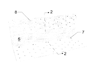
Fig. 1 schematically shows a front perspective view of the connector piece.
Fig. 2 shows an enlarged section of views along line 2-2 of Figs. 1, 3 and 4
of the connector piece
connected to the wooden parts 6, i.e. a wall and a floor.
Fig. 3 shows a front view of the connector piece.
Fig. 4 shows a top view of the connector piece.
DETAILED DESCRIPTION
As shown in Figure 2, which is a section taken along the line 2-2 of Figure 1
the connector piece 1
is composed of a metal plate 5, preferably made of steel, with a thickness
that preferably ranges
from 3 mm to 6 mm, and is advantageously 4 mm, folded at an angle of
substantially 90 +-5" to
form an angle section.
The plate 5 is divided by folding axis into a vertical part of the plate 3 and
a horizontal part 4. The
vertical side 3 of the connector piece is formed with a series of first holes
8 whose diameter d
preferably ranges from 4 mm to 6 mm, and is advantageously 5 mm; the
horizontal side, e.g. In
one embodiment, is formed with 35 holes 8 whose diameter d ranges from 4 mm to
6 mm, and is
advantageously 5 mm. The horizontal side of the connector piece, near the 90'
folding axis is
formed with a second series of holes having a greater diameter n, preferably
ranging from 9 mm to
15 mm, and advantageously 12 mm. The first holes 8 with the diameter d are
adapted to receive
smooth or grooved nails, screws or similar, whereas the second holes 7 with
the diameter n are
adapted to receive fully threaded screws, that form an angle a ranging from 60
to 85"with respect
Date Regue/Date Received 2023-01-19
6
to the horizontal plane.
Figure 3 shows the distance b of the holes 8 from the upper edge and the same
distance b
between the holes, which may be, for example, 10 mm. The distance c of the
holes 8 from the
lower edge is, for example, 60 mm. The distance of the holes 8 from the left
and right edges is
advantageously 11 mm. In a preferred embodiment, the holes 8 in the vertical
direction are offset
by a distance f, advantageously 5 mm. The vertical rows of holes 8 are
arranged with a center-to-
center distance g, advantageously 19 mm. The distance h between the holes 8 in
the horizontal
direction is preferably 38 mm.Fig. 4 shows, according to a preferred example,
the distance of the
center of the holes 7 from the outer edge of the vertical side, which in this
example is about 13 mm.
The distance j between the holes 7 and the holes 8 is advantageously 20 mm.
The holes 8 of the
row on the horizontal side of the element are offset by a distance k,
advantageously 5 mm. The
minimum distance between the rows of the holes 8 may be, for example, the
distance I of 7 mm.
The distance m of the holes 8 from the opposite edge of the vertical side of
the connector piece
may be 10 mm. The distance of the holes 7 from the left and right edges is
advantageously at least
or exactly 27 mm. The distance p between the holes 7 in the horizontal
direction is advantageously
at least or exactly 55 mm. The distance q of the holes 8 from left edge is for
example 14 mm, and
the distance s from the right edge is for example 13 mm. The vertical rows of
holes 8 are offset in
the horizontal direction by a distance r, for example 19 mm.
Advantageously, the connection system formed by a connection consisting of a
connector piece of
the invention which connects a first wooden construction part 6 with a second
wooden construction
part. The two elements form a substantially right angle. The connector piece
is fastened with a first
series of fully threaded screws, which fit into the holes 7 at an angle a
ranging from 60 to 85
formed by the screw and the plate with the holes, advantageously about 75 .
These holes are
arranged substantially adjacent to the folding line at a distance of not more
than 25mm,
Date Regue/Date Received 2023-01-19
7
advantageously 5 mm. The connection is secured with a second series of nails
and/or screws in
the holes 8. These second screws/nails have a smaller diameter than the first
series of fully
threaded screws, which and fit into the holes substantially perpendicularly to
their respective plate
and into the two wooden construction parts. Advantageously the fully threaded
screws do not
require a washer/ring to be interposed between the plate and their head.
It will be finally appreciated that the system and connector as described
heretofore are susceptible
of additions, changes or variants that would be obvious to the skilled person,
without departing
from the scope of the invention as defined by the appended claims.
List of references
1 connector piece
2 section line, 2-2
3 lower plate part
4 upper plate part
metal plate
6 wooden construction part
7 hole
8 hole
9 fully threaded screws
a angle
b,p,h,g,r,k,l,f distance between holes
e,o,q,s distance of holes from edge
I,c distance of holes from folding axis
j distance between first and second holes
d,n diameter of holes
Date Regue/Date Received 2023-01-19