Note: Descriptions are shown in the official language in which they were submitted.
APPARATUS AND METHOD FOR CLEANING MACHINES
TECHNICAL FIELD
[0002] The present disclosure may relate to a cleaning apparatus which is used
in industiy for
the purposes of cleaning large machine and motor parts, such as engine blocks.
Related
methods may also be described.
BACKGROUND
[0003] When repairing or reconditioning a machine, it may be required to clean
parts of that
machine. For instance, when reconditioning engines, engine parts may often be
covered in
grease, oil, and/or exhaust debris and thus may require cleaning to ensure the
engine is able to
operate as efficiently as possible once re-assembled. Generally, cleaning may
be done in a
chemical bath and/or in specially-designed cleaning equipment.
[0004] The use of a chemical bath, while effective, may take a long time to
completely clean
the part. Chemical baths may typically have a large volume of one or more
chemicals
contained in a vessel Nvhich is able to be agitated. The part to be cleaned
may then be
submerged in the chemical(s) and may sit in the bath for a significant amount
of time in order
to allow the chemical to clean the product. Chemical baths may be a very slow
way of
cleaning a part and also may present significant safety and environmental
issues due to the
nature of the chemical(s) (typically a caustic soda).
[0005] Cleaning equipment generally may comprise a housing having an opening
at its upper
face which is controlled by a closure. The interior of the housing may define
a washing
chamber which may accommodate a basket intended to receive machine parts and
the like
and which may be driven to rotate about its central axis within the housing.
The washing
chamber may be associated with a suitable spray system intended to direct a
washing solution
on to the parts being carried by the basket. Generally, the basket may be
rotated while the
spray system may remain fixed.
[0006] Cleaning equipment may be designed to suit particularly-sized parts.
For example, a
size of the housing, the design of the basket, and/or the associated spray
system may be
1
Date recue/Date received 2023-04-05
CA 03049934 2019-07-11
WO 2017/203357
PCT/1B2017/000714
tailored to dimensions of parts the cleaning equipment may be used to clean.
Current
cleaning equipment may fall short for larger parts.
[0007] Due to size, cleaning equipment designed for large parts may lack
portability and may
take up a large area of floor space. The need for a large floor space may also
be required to
allow the part to be loaded into and unloaded from the cleaning equipment.
Logically, in
order to load and unload the part into the cleaning equipment, the opening of
the cleaning
equipment may need to be suitably sized. This opening may generally be closed
by doors
that may swing open and thus may need room to open and be positioned so as not
to hinder
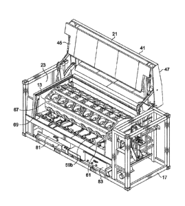
the loading and unloading of the parts. This may increase the amount of floor
space required
to accommodate the cleaning equipment.
[0008] Due to the cleaning equipment's lack of portability, operators who need
parts cleaned
on a regular but perhaps not full-time basis may need to transport the parts
to a location
where there is suitable cleaning equipment. Alternatively, operators may rely
on a process of
cleaning which may be substandard. These delays in the repair/reconditioning
of the part
caused by the cleaning process may add considerable expense to the process.
[0009] Further, the position of the opening and the operation of the doors of
cleaning
equipment may make it difficult to load and unload a large part using an
overhead crane.
Such loading may require an operator to assist in manoeuvring the part into
and out of the
cleaning equipment, which may create an unsafe work environment.
[0010] As machinery, such as trucks and trains, become larger and more
powerful, their
engines and other parts may also increase in size and weight. For instance, an
engine block
of a V12 or V16 locomotive engine may be too large to be cleaned in current
cleaning
equipment. Due to the weight and shape of these parts, rotating baskets in
available cleaning
equipment may not readily support the load. Furthermore, the closure may make
it very
difficult to load and unload the part. Another difficulty may include the
spray system of the
cleaning equipment being unable to adequately clean the part's interior
cavities.
[0011] Current cleaning techniques may not effectively clean parts of large
size. In some
attempts, a cleaning machine without a rotating basket may be utilized to
clean the engine
block, whereby the engine block may be placed vertically in the cleaning
machine. However,
and setting aside difficulties in loading and unloading the part, the engine
part may be prone
to distortion as a result of being in a vertical orientation for such a period
of time.
Furthermore, this method may not facilitate the cleaning of the cavities of
the engine block.
[0012] In relation to chemical baths, the engine block may be required to sit
in a bath for 2-3
days and may require at least 20000 liters of chemical, which may be
prohibitively time
2
CA 03049934 2019-07-11
WO 2017/203357
PCT/1B2017/000714
consuming and expensive. Another option may be to manually clean the part.
This method
of cleaning not only may provide a substandard level of cleaning, but also may
require a
significant amount of time (e.g., at least 200 hours) as well as a large
volume of solvent.
[0013] The preceding discussion of the background art may be intended to
facilitate an
understanding of the present disclosure only. The
discussion may not be an
acknowledgement or admission that any of the material referred to is or was
part of the
common general knowledge as at the priority date of the application.
SUMMARY
[0014] In one embodiment of the present disclosure, a cleaning apparatus may
be described
which may ameliorate, mitigate, and/or overcome at least one disadvantage of
the prior art.
At the very least, embodiments described herein may provide the public with a
practical
choice for cleaning large parts of machinery, particularly engines.
[0015] Throughout the specification the terms `Van" and/or "parts" may be used
to describe
machinery and/or machinery parts and can include engine blocks.
[0016] The present disclosure may provide a cleaning apparatus for cleaning
parts. The
cleaning apparatus may comprise a housing defining a washing chamber. The
washing
chamber may have an opening through which parts may be loaded/unloaded into
the washing
chamber. The cleaning apparatus may also comprise a support cradle adapted to
support
components to be cleaned. The support cradle may be located in the washing
chamber. The
cleaning apparatus may also comprise a spray system adapted to direct a
washing solution to
clean the part in the washing chamber. The cleaning apparatus may also
comprise a closure
which may provide controlled access to the washing chamber through the
opening. The
closure may be movable between a closed position to sealingly close the
opening and an open
position to allow for loading and unloading of parts into the washing chamber.
When in an
open position, the closure may be supported in a position away from the
opening such that
the closure does not provide an obstruction to the opening.
[00171 In contrast to the prior art, the closure may open in a manner which
does not
substantially increase the footprint of the cleaning apparatus. When in an
open position, the
closure may consume a minimum of plan area in the work space so as to not
encroach upon
the working space in front of or to the sides of the cleaning apparatus.
[0018] In some embodiments, the housing may comprise a frame having panels
secured
thereto. The opening may be located in a portion of the upper surface above
the washing
chamber. The opening may extend from the opening in the upper surface into a
sidewall
3
CA 03049934 2019-07-11
WO 2017/203357
PCT/1B2017/000714
adjacent the washing chamber. Preferably the opening extends over a large
portion of the
upper surface and a large portion of the sidewall. Preferably the opening in
the upper surface
extends across the washing chamber. In this configuration the opening allows
for loading
and unloading through the upper surface of the housing and/or the side wall.
As the opening
extends from the upper surface into the sidewall, the part may be enabled to
be
moved/adjusted in a horizontal direction when unloading/loading.
[00191 The closure may comprise a lid comprising a first panel and a second
panel. The first
panel may be hingedly connected to the second panel. When the closure is in
the closed
position the first panel may be located over the opening in the sidewall, and
the second panel
may be located over the opening in the upper surface. Preferably, when the
closure is in the
open position, the lid may be in a collapsed configuration wherein the first
panel and second
panel are located side by side. The first panel may be received within the
second panel.
Preferably, when in the collapsed configuration, the first panel and second
panel may be in a
substantial vertical orientation. Preferably, when in the collapsed
configuration, the first
panel and the second panel may be positioned away from the opening such that
they do not
obstruct the opening when unloading/loading parts into the washing chamber.
This may
enable parts to be loaded/unloaded vertically, and may allow for easier
positioning and
maneuvering of parts when using cranes. Furthermore, as the movement of the
lid is
predominantly in the space above the footprint of the housing, the cleaning
apparatus may be
positioned in a smaller area when compared to prior art as there is no need to
accommodate
doors which swing open.
[0020] As the lid opens upwardly, the cleaning machine may not require as much
floor space
when compared to the prior art. This may be achieved without compromising an
operator's
requirement to access the washing chamber as the operator may access the
washing chamber
through the opening in the sidewall.
[0021] In some embodiments, the closure may comprise a linkage system which
may move
the lid between the open position and the closed position. The linkage system
may be located
outside the washing chamber. The linkage system may operatively engage each
side of the
lid. The linkage system may cause the first panel of the lid to rotate
inwardly towards the
second panel as the closure moves from the closed position to the open
position. In some
embodiments, the angle of the first panel relative to the second panel may
remain fixed
during a first stage of the closure moving towards the open position. The
first stage may be
defined by commencement of the movement of the closure from the closed
position to the
second position, and may terminate once the closure has moved sufficiently
away from the
4
CA 03049934 2019-07-11
WO 2017/203357
PCT/1B2017/000714
housing such that the first panel may rotate towards the second panel without
hitting the
housing or the part to be cleaned.
[0022] In some embodiments, the linkage system may cause the lid to first move
upwardly as
the lid starts to move from the closed position to the open position. When the
lid is in the
closed position, the linkage system may be predominantly located within the
housing but
external to the washing chamber.
[0023] The linkage system may also comprise a plurality of linkage arms and an
actuator at
each end of the lid. The actuator may cause movement of the plurality of
linkage arms in
order to move the lid,
[0024] The support cradle may transfer loads thereon directly to the floor. As
the loads are
distributed directly to the floor, the housing of the cleaning apparatus may
not need to be
designed to support such a load. This may significantly reduce the weight of
the housing.
Additionally, the support cradle may be adjustable.
[0025] In an embodiment wherein the part to be washed is an engine block, the
support
cradle may support the engine block in a substantially horizontal orientation
or at a small
angle relative thereto. The small angle may be less than approximately 5
degrees. By
supporting the engine block at a slight angle to its horizontal orientation,
the washing solution
may be better able to drain away,
[0026] The support cradle may also comprise a plurality of pedestals. Each of
the pedestals
may directly engage the engine block. The plurality of pedestals may be in the
form of a first
pair of pedestals and a second pair of pedestals. There may be additional
pairs of pedestals as
required. These variations are understood to be within the scope of the
present disclosure.
[0027] The first pair of pedestals may include a projection extending upwardly
therefrom
such that upon loading the engine block into the washing chamber an end of the
engine block
is located relative to the projection and is supported upon the first
pedestal. When the engine
block is that of a v12 engine, the second pedestal may be positioned such that
the other end of
the engine block aligns with the second pair of pedestals. When the engine
block is that of a
v16 engine, the second pedestal may be positioned such that a portion of the
engine block
overhangs the second pedestal. The pedestals may support the engine block at
the same
position the engine is designed to be mounted when in use. The position of the
engine block
on the pedestal ensures the spray system is able to properly align with the
engine block.
[0028] The top of the pedestals may comprise a support runner thereon. The
support runners
may provide a surface to assist in centering the block within the washing
chamber. The
CA 03049934 2019-07-11
WO 2017/203357
PCT/IB2017/000714
support runners may be dimensioned such that the engine block, when supported
thereon, is
at a slight angle to the horizontal.
[0029] The washing chamber may include a plurality of guides to guide the part
into the
washing chamber and on to the support cradle as the part is being loaded into
the washing
chamber.
[0030] The spray system may comprise a plurality of spray arrays arranged to
clean the part.
Each spray array may provide a plurality of spray heads. In one aspect, the
spray array may
be in the form of a spray bar which supports the plurality of spray heads. The
spray bar may
rotate between a first angular position and a second angular position.
[0031] In another aspect, the spray array may move and oscillate a plurality
of spray arms.
Each spray arm may support the spray head at an end thereof. The spray head
may rotate
independently or in tandem with other spray heads. Each head may comprise
three nozzles
wherein each nozzle is orientated at different angles. Each spray arm may be
individually
controlled and adjusted. One or more spray arms in an array may be adjusted so
as not to
deliver any fluid to the part.
[0032] In another aspect of the present disclosure, the plurality of spray
arrays may include a
combination of the spray arrays as herein before described. The spray head may
also deliver
recycled water to the part. The recycled water may have particles therein up
to
approximately 3mm in diameter. The particles in the washing solution and/or
recycled water
may include abrasives if helpful for the cleaning process.
[0033] In some embodiments, each spray head may comprise one or more brakes to
slow
down rotation of the head. This brake may be in the form of a magnetic brake.
Slowing
down the rotation of the spray head may result in better spray dwelling which
may increase
the efficiency of the cleaning process.
[0034] Further, each spray head and/or nozzle may be operated independently
and/or
positioned independently. For example, one or more spray heads and/or nozzles
may be
turned off to increase pressure to other spray heads and/or nozzles, depending
on
requirements of a particular cleaning operation.
[0035] One or more spray arrays may be configured to clean a cavity within the
part. In
some embodiments, the spray arrays may be configured to clean inner surfaces
of the cavity.
The one or more spray arrays may be configured to move the spray arms from a
non-spray
position, to a first spray position wherein at least the head of each spray
arm is located at a
first position within the cavity. The one or more spray arrays may be
configured to move the
spray arms to a second spray position wherein at least the head of each spray
arm is located at
6
CA 03049934 2019-07-11
WO 2017/203357
PCT/1B2017/000714
a second position within the cavity. The cavity may comprise a first cavity
portion wherein
the first position lies, and a second cavity portion wherein the second
position lies. The spray
system may configure the spray arms at further positions within the cavity as
may be
required. These variations are understood to be within the scope of the
present disclosure.
[0036] One or more further spray arrays may be configured to move the spray
heads at
multiple positions relative to an opening of a recess or a cavity such that
head is able to direct
washing solution to all internal surfaces of the recess/cavity. The one or
more further spray
arrays may be mounted in the lid.
[0037] The spray system may be pneumatically operated whereupon lack of
pressure results
in the spray system returning to a non-spray, retracted position. In the
retracted position the
spray arrays are positioned such that the part may be loaded/unloaded into the
washing
chamber. Each spray array of the spray system may comprise a plurality of
bumpers which
may be adapted to protect the spray array as well as the part should the spray
array engage the
part.
[0038] The spray system may also comprise one or more actuators to operate the
spray
arrays. The actuators may actuate the spray arrays in a manner whereby, should
a part of the
spray array engage the part, the actuator may not exert excessive force
thereon. In this regard
the actuators may balance the movement of the spray array with that of
engaging an obstacle.
This may not only protect the part but also may minimize the risk of breaking
a spray arm
and/or spray array. Additionally, the spray arms may be removed, replaced,
and/or
repositioned. This may allow a spray array to be tailored to clean different
parts, such as
differently-sized engine blocks.
[0039] In some embodiments, the cleaning apparatus may further comprise a
fluid supply
system. The fluid supply system may comprise a filtration system for treating
the washing
solution and a reservoir for holding the washing solution. The filtration
system may treat the
washing solution so that it may be recycled and be fed to the spray arrays
multiple times
during a wash cycle. The filtration system may comprise at least one screen, a
settling
reservoir/overflow region, and/or a flotation reservoir/underflow region. The
filtration
system may also comprise an outlet wherein the outlet is located to draw fluid
from a mid-
point (e.g., a height) from the filtration system. The outlet may be in fluid
communication
with the reservoir.
[0040] The filtration system may be in the form of a tray which moves from an
in-use
position to an extended position wherein the tray may be serviced by an
operator. As the tray
7
CA 03049934 2019-07-11
WO 2017/203357
PCT/1B2017/000714
slides out of the housing the operator may not be required to enter the
housing in order to
clean and service the filtration system.
[0041] In some embodiments, the reservoir may store the washing solution
and/or may
provide a heating unit to heat the fluid for cleaning. The reservoir may have
a flow control
device connected to an external supply. The flow control device may deliver
fluid to the
reservoir in order to fill the reservoir prior to and/or during a cleaning
cycle.
[0042] The fluid supply system may also comprise a pump for circulating fluid
through the
spray system. The pump may be located within the housing but external to the
washing
chamber, or in another location. For example, the pump may be slidably
received in the
housing for ease of servicing.
[0043] Again, the present disclosure may provide a cleaning apparatus for
cleaning parts.
The cleaning apparatus may comprise a housing defining a washing chamber. The
washing
chamber may have an opening through which parts may be loaded/unloaded into
and out of
the washing chamber. The cleaning apparatus may also comprise a support cradle
adapted to
support components to be cleaned. The support cradle may be located in the
washing
chamber. The cleaning apparatus may also comprise a spray system adapted to
direct a
washing solution to clean the part in the washing chamber. The cleaning
apparatus may also
comprise a fluid supply system comprising a filtration system and a reservoir
wherein the
filtration system treats the washing solution before it passes into the
reservoir. The treated
washing solution may be reused in the spray system. The cleaning apparatus may
also
comprise a closure which provides controlled access to the washing chamber
through the
opening. The closure may be movable between a closed position to sealingly
close the
opening, and an open position to allow for loading and unloading of parts into
and out of the
washing chamber. When in an open position, the closure may be supported in a
position
away from the opening such that the closure does not provide an obstruction to
the opening.
BRIEF DESCRIPTION OF THE DRAWINGS
[0044] Further features of the present disclosure may be more fully described
in the
following description of several non-limiting embodiments thereof This
description may be
included solely for the purposes of exemplifying the present disclosure. It
may not be
understood as a restriction on the broad summary, disclosure, and/or
description of the
disclosure as set out above. The description may be made with reference to the
accompanying drawings.
8
CA 03049934 2019-07-11
WO 2017/203357
PCT/1B2017/000714
[0045] FIGURE 1 is a front perspective view of a cleaning apparatus according
to an
embodiment of the present disclosure, the cleaning apparatus is shown without
panels and
with a closure in a first position.
[0046] FIGURE 2 is a front perspective view of the cleaning apparatus shown in
FIGURE 1
with an engine block located therein, the cleaning apparatus is schematically
represented
without panels and a lid of the closure.
[0047] FIGURE 3 is a front perspective view of the cleaning apparatus shown in
FIGURE 1
having the closure in an open position and having an engine block located
therein.
[0048] FIGURE 4 is an end perspective view of FIGURE 3.
[0049] FIGURE 5 is a front view of FIGURE 3.
[0050] FIGURE 6 is a side view of FIGURE 3.
[0051] FIGURE 7 is a side view of the closure shown in FIGURE 1, the closure
is located in
an intermediary position between an open position and a closed position.
[0052] FIGURE 8 is a side view of a part of the engine block supported on a
support cradle
of the cleaning apparatus of FIGURE 1.
[0053] FIGURE 9 is a side perspective view of a spray system of the cleaning
apparatus
shown in FIGURE 1 with an engine block located therein.
[0054] FIGURE 10 is a cross sectional view of the spray system relative to a
first cavity of
and surrounding surfaces of the top of the engine block.
[0055] FIGURE 11 is a cross sectional view of the spray system relative to a
second cavity of
the engine block.
[0056] FIGURE 12 is a cross sectional view of the spray system relative to a
second cavity of
the engine block.
[0057] FIGURE 13 is a front perspective view of a filtration system of the
cleaning apparatus
shown in FIGURE 1 wherein the filtration system is in an open condition.
[0058] FIGURE 14 is a rear perspective view of FIGURE 13.
[0059] FIGURE 15 is a perspective view of an alternative filtration tank
having one side cut
away.
[0060] FIGURE 16 is a plan view of the filtration tank shown in FIGURE 15.
[0061] FIGURE 17 is a front perspective view of a cleaning apparatus according
to a second
embodiment of the present disclosure having an engine block located therein,
and a lid of the
closure in an open position.
[0062] FIGURE 18 is a perspective view of a spray head.
[0063] FIGURE 19 is a side view of the spray head of FIGURE 18.
9
CA 03049934 2019-07-11
WO 2017/203357
PCT/1B2017/000714
[0064] FIGURE 20 is a front view of the spray head of FIGURE 18.
[0065] FIGURE 21 is a cross-sectional view of the spray head of FIGURE 18.
[0066] In the drawings like structures are referred to by like numerals
throughout the several
views. The drawings shown are not necessarily to scale, with emphasis instead
generally
being placed upon illustrating the principles of the present disclosure.
DESCRIPTION OF EMBODIMENTS
[0067] The present disclosure may be suited to clean large machines and
machine parts and
obviates the need to manually clean the part, or to use expensive and
dangerous chemical
baths. While other specialized cleaning equipment may be available for
cleaning machine
parts, these may all be based on rotation of a basket for effective cleaning.
Large, heavy parts
may not be cleaned in this type of equipment as the part would be too heavy to
be
accommodated by a rotating basket.
[0068] FIGURES 1 to 14 may show a cleaning apparatus 11 according to a first
embodiment
of the present disclosure. In this embodiment, the cleaning apparatus 11 may
be particularly
suited to clean a part in the form of an engine block 13 from a V12 or V16
engine. It may be
noted that the cleaning apparatus 11 of the present disclosure may be designed
to clean other
large parts and that such a design is considered to be within the scope of the
present
disclosure. To date there may be no comparable cleaning option to clean this
size of part
when considering the cleaning apparatuses of the prior art.
[0069] As shown in FIGURES 1-6, the cleaning apparatus 11 may comprise a
housing 15. In
this embodiment, the housing 15 may be similar in dimensions to a sea/shipping
container.
This may enable the cleaning apparatus 11 to be readily stored and transported
using standard
equipment. The housing 15 may house substantially all components of the
cleaning
apparatus 11. The housing may comprise a frame 17 to which panels (not shown)
may be
secured. The frame 17 and associated panels may provide the required strength
and rigidity
to enable the cleaning apparatus 11 to be transported.
[0070] As shown in FIGURE 2, a washing chamber 19 may be defined within an
interior of
the housing 15. The washing chamber 19 may receive the engine block 13 and may
provide a
substantially sealed chamber during a washing cycle to contain washing
solution within the
housing 15.
[0071] The cleaning apparatus 11 may further comprise a closure 21 for closing
an opening
23 in the housing 15. The opening 23 may be sufficient in size to allow for
unobstructed
loading and unloading of the engine block 13 into/from the washing chamber.
The opening
CA 03049934 2019-07-11
WO 2017/203357
PCT/1B2017/000714
23 may be defined in a portion of an upper surface 25 of the housing 15 and
may extend
down an adjoining sidewall 27. As noted in FIGURES 1 and 2, the frame 17 may
not extend
across a front upper edge of the washing chamber 19 as this may cut across the
opening 23.
[0072] FIGURE 3 shows that the opening 23 in the upper surface 25 may be
located directly
above the washing chamber 19. This positioning may enable the engine block 13
to be
loaded vertically (e.g., from above) into the washing chamber 19 using a crane
(not shown).
This also may allow the engine block 13 to be lowered from above and into the
washing
chamber 19 in a generally horizontal orientation ready for cleaning, thereby
negating the need
to maneuver the engine block 13 within the washing chamber 19 before it can be
cleaned.
Additionally, as the sidewall 27 may also provide part of the opening 23, the
engine block 13
may be freely moved in/loaded from a lateral direction, such as may be
required when using a
forklift.
[0073] As shown in FIGURES 4-6, the cleaning apparatus 11 may also comprise a
support
cradle 29 for supporting the engine block 13 when positioned within the
washing chamber
19. While the support cradle 29 may be secured relative to the housing 15, the
support cradle
29 may be configured such that the load experienced by the support cradle 29,
including any
shock load as may occur when loading an engine block 13 thereon, may be
distributed
through the floor upon which the cleaning apparatus 11 sits. As a result, the
cleaning
apparatus 11 may not need to be engineered to take the load of the engine
block 13, allowing
the housing 15 to be made from less material, reducing cost and weight. The
floor may have
additional footings poured where the cleaning apparatus 11 may be positioned
to assist in
distributing the load within the floor.
[0074] As shown in FIGURE 8, the support cradle 29 may comprise two (or
multiple) pair
of pedestals 31, 33. Each pair of pedestals 31, 33 may be located relative to
the washing
chamber 19 such that the engine block 13 may be supported on its safest, flat
load bearing
surface. The first pair of pedestals 31 may be designed to receive a first end
35 of the engine
block 13. To assist in locating the engine block 13 thereon, the first pair of
pedestals 31 may
have an upwardly extending projection 37. As the engine block 13 is being
lowered into the
washing chamber 19, the first end 35 of the engine block 13 may abut the
projection 37 so as
to locate the engine block 13 relative to the support cradle 29.
[0075] The second pair of pedestals 33 of the support cradle 29 may support
the engine block
13 such that the center of gravity of the engine block 13 is located between
the two pair of
pedestals 31, 33. When the cleaning apparatus 11 is configured to clean an
engine block for a
11
CA 03049934 2019-07-11
WO 2017/203357
PCT/1B2017/000714
V12 engine, for example, the second pair of pedestals 33 may be located at a
second end of
the engine block 13.
[0076] Each pair of pedestals 31, 33 may have a support runner 39 along the
top. The
support runners 39 may be configured to centrally locate the engine block 13
relative to its
longitudinal axis. The support runners 39 may each be formed from steel and
may have a
plastic strip thereon for protecting the engine block 13. The plastic may have
high impact
resistant characteristics (e.g., Polytetrafluoroethylene (PTFE) and/or
Polyoxymethylene
(POM)). The support runners 39 may have different thicknesses such that when
the engine
block 13 is supported thereon, the engine block 13 may be angled relative to
the horizon by
approximately 1 degree. This may assist in drainage of the washing solution,
preventing
pooling within the engine block 13.
[0077] Once the engine block 13 is loaded in the washing chamber 19, the
opening 23 may
be closed by the closure 21. As shown in FIGURES 3-7, the closure 21 may
comprise a lid
41, which may be movable from a closed position to an open position by a
linkage system 43
(and vice versa).
[0078] As seen in FIGURES 3, 4, and 7, the lid 41 may comprise a first panel
45 which is
hingedly connected to a second panel 47. When the closure 21 is in the closed
position, the
first panel 45 may close the portion of the opening 23 in the sidewall 27 of
the housing 15,
while the second panel 47 may close the portion of the opening 23 in the upper
surface 25.
[0079] When the closure 21 is in the open position as seen in FIGURES 3-6, the
first panel
45 and the second panel 47 may be in a vertical orientation in a side by side
relationship.
When in this position, the lid 41 may be in a collapsed arrangement above the
housing 15 and
may be spaced away from the opening 23. In this arrangement, the lid 41 may
not encumber
the loading and unloading of the engine block 13 relative to the washing
chamber 19.
Furthermore, as the open lid 41 is in the space above the housing 15, the
footprint of the
cleaning apparatus 11 may be minimized as it does not have doors which open
outwardly
from the side of the housing 15. Furthermore, as the opening 23 also extends
along the
sidewall 27, operators may be readily able to access the washing chamber 19 to
inspect the
engine block 13 and to conduct maintenance on the washing chamber 19.
[0080] When the lid 41 is in the closed position, the linkage system 43 may be
located within
the housing 15 yet external to the washing chamber 19. As shown in FIGURES 3-
7, the
linkage system 43 may comprise a set of linkage arms 49 located at opposed
ends of the lid
41. Each set of linkage arms 49 may be operatively connected to an actuator 51
for
movement of the lid 41 between the open position and the closed position. The
actuator 51
12
CA 03049934 2019-07-11
WO 2017/203357
PCT/1B2017/000714
may cause movement of the plurality of linkage arms 49 in order to move the
lid 41. In the
event the cleaning apparatus 11 malfunctions or fails, the actuator 51 may
cease movement
and may hold the lid 41 in the position it was in when the cleaning apparatus
malfunctioned.
[0081] As seen in FIGURE 7, each set of linkage arms 49 may comprise linkage
arms 49c,
49d and 49e. These may operate within the confines of the housing 15 and
eliminate the need
for pivot points extending outside the housing 15.
[0082] In the initial stage of moving the lid 41 from the closed position to
the open position,
linkage arm 49d may cause the lid 41 to first move in an upward direction away
from the
opening 23. As the lid 41 approaches the open position, linkage arm 49f may
cause the lid 41
to be held in a vertical orientation rearwardly from the opening 23 as seen in
FIGURES 3-6.
[0083] As the lid moves from the closed position to the open position, the
first panel 45 may
be caused to move towards the second panel 47. Linkage arm 49g may cause the
first panel
to rotate about an axis extending along an edge portion 55 where the first
panel 45 is
connected to the second panel 47. However, linkage arm 49g may only cause the
first panel
45 to rotate inwardly towards the second panel 47 once the first panel 45 is
sufficiently clear
of the housing 15. This may ensure that the lid 41 is able to freely collapse
as it moves to the
open position without hitting the housing 15 (see FIGURE 6).
[0084] In some embodiments, the washing chamber 19 may comprise a series of
guards (not
shown) located around the opening 23. The guards may protect seals (not
pictured) located
between the lid 41 and the opening 23 to minimize the risk of washing solution
leaking from
the housing 15 during operation.
[0085] Referring now to FIGURE 9, the cleaning apparatus 11 may additionally
include a
spray system 57 which sprays a washing solution onto the engine block 13
during cleaning
operations. A spray array 59 (e.g., spray array 59a, spray array 59b) may be
supported on an
underside of the second panel 47 of the lid 41 and move with the lid 41. This
may ensure the
spray arrays 59a do not affect the loading and unloading of the engine block
13.
[0086] The engine block 13 may include two main regions which require
cleaning. These
two regions may each require a differently configured spray array to provide
adequate
cleaning. One region may be the top of the engine block 13 which has a first
set of cavities
67 and surfaces defined in the upper portion of the engine block 13. This
first region
provides the valve train sections. The second region may incorporate a second
set of cavities
69 defined in the lower portion of the engine block 13.
[0087] The spray system 57 of the present embodiment may comprise a number of
spray
arrays 59 (e.g., spray arrays 59a of FIGURE 10, 59b of FIGURES 3 and 9-11)
that
13
CA 03049934 2019-07-11
WO 2017/203357
PCT/1B2017/000714
corresponds to a number of cavities 67, 69 of the engine block. For example,
in a V12
engine, the spray system 57 may include six spray arrays 59. Of these six
spray arrays 59,
four spray arrays 59a may be configured to clean the upper region of the
engine block 13
including the cavities in the top of the engine block 13 (e.g., cavities 67),
while the remaining
two spray arrays 59b may be configured to clean cavities in either side of the
engine block 13
(e.g., cavities 69). Each spray array 59 comprises a plurality of spray heads
63 (e.g., spray
heads 63a and 63b) as seen in FIGURES 3, 4, and 9-12 and as described in more
detail with
reference to FIGURES 18-21.
[0088] As the engine block 13 may be relatively symmetrical, the below
disclosure relates to
cleaning operations performed to one side of the engine block 13 only.
However, it is to be
understood that a similar configuration may apply to the other side of the
engine block 13.
[0089] Consider a cavity 67a of the first set of cavities 67 located in the
top of the engine
block 13 as shown in FIGURE 10. In order to clean the inner surface of the
cavity 67a, spray
may be delivered relative to a cavity opening 71 from different
locations/angles. To
efficiently achieve this result, the spray system 57 may allocate two spray
arrays 59a to the
first set of cavities 67, and each spray array 59a may provide a spray head 63
to a
corresponding cavity 67a. During a cleaning cycle, two spray heads 63a may be
positioned
relative to each cavity opening 71 so as to be directed toward the cavity 67a
in an angular
spaced relation to each other.
[0090] To also clean the surfaces surrounding each cavity 67a, as well as to
improve the
cleaning action of the spray heads 63a, each spray array 59a may comprise a
rotating spray
bar (e.g., spray arm 61 and/or another element) upon which the spray heads 63a
may be
mounted. The spray bar may be able to rotate approximately 55 degrees about
its central axis
causing a line of spray from the spray head 63a to sweep both an inner surface
of the cavity
67a and surrounding surfaces.
[0091] Consider a cavity 69a of the second set of cavities 69 located in the
side of the engine
block 13. As shown in FIGURES 11 and 12, cavity 69a may comprise two distinct
sub-
cavities and spray array 59b may be configured to clean the inner surface of
each of the sub-
cavities.
[0092] Spray array 59b may comprise eight spray arms 61, each having a spray
head 63b at
an end thereof Each spray arm 61 of the spray array 59b may be adapted to
position the
spray head 63b in the cavity 69a at a first position and a second position,
the first position
being located within one of the sub-cavities (FIGURE 11) and the second
position being
14
CA 03049934 2019-07-11
WO 2017/203357
PCT/1B2017/000714
located within the other sub-cavity (FIGURE 12). With this arrangement the
spray head 63b
may clean the entire inner surface of the cavity 69a.
[0093] During the cleaning cycle of the cavity 69a, a portion of one of the
spray arms 61 may
enter the cavity 69a to locate the spray head 63b at the first position. In
this position, the
spray head 63b may be able to clean the first sub-cavity of the cavity 69a.
Once this is
complete, the spray array 59b may cause the spray arm 61 to move further
within the cavity
69a such that the spray head 63b may be located at the second position. In
this position, the
spray head 63b may be able to clean the second sub-cavity of the cavity 69a.
[0094] In some embodiments, and as shown in FIGURES 18-21, the spray head 63
of the
spray array 59 may be a rotating spray head and may comprise three nozzles 65
angularly
orientated with respect to each other. The spray head 63 may include flat
spray nozzles 65.
Each spray head 63 may comprise a magnetic brake 66 therein for slowing down
the rotation
of the spray head 63 and/or each individual nozzle 65. This may increase the
efficiency of
the cleaning process as the spray has a longer dwell. In some embodiments,
each spray head
63 and/or each individual nozzle 65 may be independently rotatable.
[0095] During operation, the spray arrays 59 may be movable from a retracted
position,
wherein the engine block 13 may be loaded/unloaded from the washing chamber
19, to a
cleaning position for cleaning the engine block 13. Additionally, each spray
array 59 may be
pneumatically controlled using an actuator mechanism 75 whereupon malfunction
of the
cleaning apparatus 11 may cause the spray array 59 to return to its retracted
position. Each
spray arm 61 may also be fitted with a bumper 73, which may minimize damage of
the
engine block 13 and the spray arm 61 should the spray array 59b cause the
spray arm 61 to
engage the engine block 13 (or another rigid obstacle).
[0096] In some embodiments, each spray array 59 may comprise eight spray heads
63. When
the engine block 13 is from a V12 engine, only six spray heads may be required
on each
spray array 59. When this is the case, any spray heads 63 not required may be
removed from
the spray array 13 and the associated hole in the spray array 59 may be
plugged.
[0097] The cleaning apparatus 11 may also comprise a fluid supply system 79.
Shown in
FIGURES 1, 3, 5, 9, and 13-14, the fluid supply system 79 may comprise a
filtration system
81 for treating washing solution, a reservoir 83 for holding washing solution,
and/or a pump
85 for circulating washing solution through the cleaning apparatus 11.
[0098] As seen in FIGURES 13 and 14, the filtration system 81 may be in the
form of a
filtration tank 87 which may be slidably received in the housing 15 such that
it may be
positioned under the washing chamber 19. The filtration system 81 may include
a screen (not
CA 03049934 2019-07-11
WO 2017/203357
PCT/1B2017/000714
shown) to first filter the washing solution as it leaves the washing chamber
19. The washing
solution then may enter an overflow region 89 of the filtration tank 87 where
heavy particles
may settle to the bottom. When the fluid level in the overflow region 89
reaches the height of
a weir wall 91, the liquid may spill over into the underflow region 93. This
region may allow
the separation of oils and other particles which float to the top.
[00991 Shown in FIGURE 14, the underflow region 93 may have a pipe 95 to
provide an
outlet 97 for allowing the fluid to exit the filtration tank 87 and pass
through hose 99 which
leads into the reservoir 83. The outlet 97 may be positioned such that the
fluid is taken from
the underflow region 93 from a position above the bottom of the underflow
region 93 and
below the surface of the fluid therein (e.g., when the fluid is close to the
top of the underflow
region 93). As the fluid is not taken from the top of the underflow region 93,
any oil or other
floating particles may remain at the surface of the fluid in the filtration
tank 87. In some
embodiments, the outlet 97 may be belled outwardly to maximize the flow while
minimizing
entrance losses in the fluid path.
[0100] In some embodiments, the underflow region 93 may be in the form of a U-
shaped
channel 92 as shown in FIGURES 13-14. The channel 92 may comprise a first
passage 94
adjacent to the weir wall 91 and a second passage 96 in which the outlet 97 is
positioned.
The first passage 94 receives the fluid as it flows over the weir wall 91 and
guides the fluid to
the second passage 96.
[0101] An alternative filtration tank 187 is shown in FIGURES 15 and 16. In
this alternative,
the second passage 96 may include a barrier 198 extending therein which is
upstream from
the outlet 97. The barrier 198 may extend vertically downward from the top of
the second
passage 96 and may terminate before the bottom of the second passage 96. The
bottom of the
barrier 198 may be shaped to limit mixing of the fluid. While the barrier 198
may allow fluid
to flow thereunder, it may prevent the top layer of fluid from flowing past
the barrier 198 and
towards the outlet 97. As a result, any oil and any floating particles carried
in the fluid may
be retained by the barrier 198 and thus prevented from flowing towards the
outlet 97, thereby
improving the quality of the fluid which passes to the reservoir 83.
[0102] The reservoir 83 may be connected to the pump 85 and may supply washing
solution
to the spray system 57. The reservoir 83 may additionally include a heating
unit 99 for
heating the washing solution.
[0103] Each of the filtration tank 87 and reservoir 83 may have a drainage
outlet 101. The
drainage outlets may be connected to waste and the contents of the filtration
tank 87 and
reservoir 83 may be drained. Once the filtration tank 87 and reservoir 83 are
drained, they
16
CA 03049934 2019-07-11
WO 2017/203357
PCT/1B2017/000714
may be slidably extended out from the housing 15 allowing an operator to clean
and/or
service the filtration tank 87 and reservoir 83. Once clean/serviced, they may
be pushed back
into the housing 15 ready for the next cleaning cycle.
[0104] The pump 85 may be housed in the housing 15 and external to the washing
chamber
19. The pump 85 may be slidably received in the housing 15 such that it may be
readily
positioned outside the housing 15 for ease of access when servicing or
replacing the pump 85.
[0105] A cleaning apparatus 211 according to a second embodiment of the
present disclosure
is illustrated in FIGURE 17. For convenience, features of the cleaning
apparatus 211 that are
similar or correspond to features of the cleaning apparatus 11 of the first
embodiment have
been referenced with the same reference numerals,
[0106] The cleaning apparatus 211 of this embodiment is similar to that of the
first
embodiment (i.e., cleaning apparatus 11). However, in this second embodiment,
a second
panel 247 of a lid 241 may be located behind the housing 215. Furthermore, a
first panel 245
may rotate outwardly relative to the second panel 247.
[0107] Referring now to FIGURES 18-21, each spray head 63 may be rotatable.
The rotating
spray head 63 according to the present disclosure may utilize a design that
addresses several
disadvantages of the present art. For example, the spray head 63 according to
the present
disclosure may be well-suited for use with dirty water or re-used cleaning
fluid. Currently
available spray heads are not recommended for use with dirty water and/or or
re-used
cleaning fluid.
[0108] Additionally, many existing "tank cleaning" rotating spray heads often
rotate very
rapidly. The speed at which the spray heads rotate may have a direct inverse
correlation to
the spray impact on the surface to be cleaned. That is, the faster the spray
heads rotate, the
lower the spray impact on the surface to be cleaned the spray has. This occurs
because, while
rotating, the spray nozzle recedes from the surface at a considerable rate
that may reduce a
relative velocity of the spray relative to the surface. High rotational speed
may also reduce a
dwell time of spray impacts on the surface. Increased dwell time can
significantly improve
cleaning efficacy.
[0109] Advantageously, the spray head 63 according to the present disclosure
is designed to
rotate at a substantially low speed governed by the friction imposed by seals
76 and/or by the
addition of a non-contact magnetic brake 66 not used by any other spray heads
in the market.
As such, the spray head 63 is able to be operated at relatively lower speeds,
thus maximizing
the cleaning effectiveness of the spray head.
17
CA 03049934 2019-07-11
WO 2017/203357
PCT/1B2017/000714
[0110] Further, some existing slow-rotation tank cleaning spray heads may rely
on a turbine
and gear system to produce its slow rotation. Advantageously, the spray head
63 according
to the present disclosure avoids the use of turbines, gears, and other
expensive and
complicated equipment for creating and controlling rotational speed. This may
enable the
spray heads 63 of the present disclosure to also avoid pressure drops ahead of
the nozzles 65
created by turbines, which would reduce the pressure and exit velocity of the
spray and thus
result in a loss of cleaning efficacy. Additionally, the spray heads 63 and
nozzles 65 of the
present disclosure may avoid wear associated with drive mechanisms as well as
jamming and
damage caused by dirty water typical of known spray heads.
[0111] Because the spray heads 63 of the present disclosure rely upon piston
seals 76 instead
of bearings (e.g., spindle bearings) for controlling rotation operations,
reused cleaning fluid,
dirty water, and/or particles below a permissible size may not affect the
rotation because
there are no tight spaces, crevices, roller elements or narrow clearances in
the spray head 63
design. The utilization of piston seals 76 in the spray heads 63 may provide
an advantage
over existing spray heads because the spray heads 63 can be used in closed
cycle cleaning
equipment that reuses cleaning fluid many times before being removed as waste.
[0112] Many tank cleaning spray heads have numerous jet orifices to ensure
spray coverage.
The spray head 63 according to the present disclosure however creates maximal
coverage
using three high-impact spray nozzles 65 as shown in FIGURES 18-21 not found
on existing
rotating spray heads. Typical three-nozzle designs of other spray heads use
"v"-type nozzles
or other nozzle types, but do not use a high-impact deflection-type nozzle 65,
which offers
the highest exit velocity possible, as utilized in the present disclosure and
shown in
FIGURES 18-21. Thus, the nozzles 65 of the present disclosure may gain an
advantage of
being more efficient than other spray head nozzles in the way they utilize
available pumping
capacity (e.g., pressure and flow rate) to produce cleaning outcomes.
[0113] The rotating spray head 63 of the present disclosure may be fitted to
an end of a spray
arm 61 or otherwise operatively coupled to the spray array 59. A fluid
delivery hose may
also be attached so as to provide cleaning fluid. During operation, the spray
heads 63 may be
introduced into a substantially enclosed space (e.g., cavities 67, 69 of
engine block 13), the
interior surfaces of which may require cleaning using high pressure spray of a
heated wash
fluid. Typically, the cavities 67, 69 may be accessed through side, top,
and/or bottom access
openings (e.g., cavity opening 71) somewhat larger than the spray head 63
itself. In some
embodiments, the spray head 63 may spray every surface within the enclosed
space that is
18
CA 03049934 2019-07-11
WO 2017/203357
PCT/1B2017/000714
within a direct line of sight to the spray head 63 (except perhaps for an area
directly behind
the spray head 63).
[0114] When spraying, a sphere of spray coverage is produced by the spray head
63 using
three flat spray nozzles 65. In some embodiments, each nozzle 65 may have an
approximately 50 degree spray pattern. The flat spray nozzles 65 may be
arranged in a plane
at three different angles so that the combined spray pattern is an arc of
approximately 150
degrees. The arc may then be rotated or revolved during spraying so that it
produces an arc
of coverage of approximately 300 degrees. The area (e.g., an approximately 60
degree arc)
directly behind the spray head 63 may not be sprayed in order to use available
pressure
delivery more effectively. Additionally, washing its own support arm 61 is not
typically a
requirement of cleaning operations, and thus spraying fluid into the openings
through which
the spray head 63 is introduced may be unnecessary and wasteful.
[0115] As seen in FIGURES 18-21, the three nozzles 65 in a plane that produce
the
approximately 150 degree arc may be further divided into two parts. In this
embodiment, the
forward directed and more rearward directed nozzles 65 are together on one
side of the plane
while a more radially directed nozzle (e.g., a center one) may be positioned
on an opposing
side of the plane. This orientation of nozzles 65 may produce an improved
balance of weight
and balance of torque, and thus may result in a spray head 63 that is less
crowded and easier
to both manufacture and assemble. The improved torque balance of the spray
head 63, for
instance, may reduce stress on the seals 76 which may act as the spray head 63
bearings.
This may contribute to the ability of the spray head 63 to dispense fluid with
conventional
bearings and thus may allow the cleaning apparatus 11 to operate with dirty
water and/or
reused cleaning fluid. As the two half planes are rotated during operation,
the resulting
approximately 300 degree arc of spray coverage may be unaffected by the
arrangement of the
nozzles 65 on opposite sides of the spray head 63.
[0116] Seen in FIGURE 21, the three nozzles 65 may be fed by radial passages
64 in the
head which may emanate from a central cavity 68 within the spray head 63 body
(and/or
other rotating element) that substantially evenly distributes wash fluid. The
central cavity 68
in turn may be fed by a number of openings in the central spindle 70 (and/or
other stationary
element). To prevent pulsing or uneven flow distribution as the spray head 63
rotates, an odd
number of spindle openings may be preferred (three are used in one
embodiment). They may
further be located in an axially offset position relative to the nozzle
passages to produce an
even more uniform flow. The radial height or clearance of the internal
cavities 64, 68 may be
19
CA 03049934 2019-07-11
WO 2017/203357
PCT/1B2017/000714
designed to be slightly greater than a throat diameter of the nozzles 65 in
order to minimize
the possibility of particles becoming lodged inside the cavity.
[0117] Fluid may be introduced into the spray head 63 through the central
cavity 68 of the
central spindle 70 (e.g., stationary element) which may be provided with
threads for hose
fittings and/or other features for connecting to a pressurized wash fluid
supply 71. In some
embodiments, and in order to minimize pressure losses, the cross-sectional
area of the central
cavity 68 of the spindle 70 may be at least twice a total cross-sectional area
of the throats of
the three nozzles 65 combined. Radial passages 64 provided in the spray head
63 for
conducting the fluid out of the central cavity 68 and through the nozzles 65
may likewise be
larger in total cross sectional area than the throats of the nozzles 65.
[0118] In one embodiment, the nozzle throat diameter (e.g., particle passing
size) may be
approximately 3 mm. Since this may be the smallest passing diameter or fluid
space
dimension in the entire spray head 63, it may be considered safe to allow
particles as large as
approximately 1.5 mm to be present in the wash fluid. In some embodiments,
however, the
fluid may actually be screened to approximately 0.5 mm.
[0119] The rotating spray head 63 may be positioned and/or held on the spindle
70 between a
polymer washer 72 (e.g., a machined POM acetyl washer, but other appropriate
plastics may
be used) on one end and a bolt and washer 74 on the other end. This bolt 74
may also double
as a plug for the central cavity 68 of the spindle 70, and when removed, the
bolt 74 may
facilitate cleaning of the spindle 70. The polymer washers 72 may minimize
galvanic
corrosion by eliminating direct bronze-to-steel wet contact.
[0120] The central cavity 68 may be sealed between the rotating head 63 and
the stationary
spindle 70 using appropriately-sized rotary piston seals 76, which may be
constructed from a
suitable polymer material compatible with the wash fluid to be used and with
the
temperatures to be used (in one application, up to 90 degrees C). In
communication with the
sealed central cavity 68 may be no crevices and/or clearances with any
dimension smaller
than the throat diameter of the nozzles 65. This may ensure that no particle
can become
trapped within the cavity and interfere with the rotation of the spray head 63
through wedging
and/or jamming any precision clearances, or interfere with the fluid flow
through the spray
head 63. Surfaces on the inside of the rotating head in contact with the seals
76 may be
polished to a specified surface finish to minimize wear of the seals 76.
[0121] The spray head 63 may be constructed to have a defined service life,
which may be
limited by the inevitable gradual erosion of the spray nozzles 65 and/or by
wear of the seals
76. When the cleaning effectiveness falls below minimum requirements, the
spray head 63
CA 03049934 2019-07-11
WO 2017/203357
PCT/1B2017/000714
may be removed from service and disassembled. It may be cleaned and re-
assembled using
new nozzles 65 and/or seals 76, and returned to service. The spray head 63 may
be designed
to be easily and readily disassembled and re-assembled in order to minimize
the time and
labour required for refurbishment. The spray head 63 design may include a
purpose-made
seal insertion tool and specific features on the spindle 70 provided to
simplify the task of seal
replacement. For example, these features may include radiusing and/or
chamfering of
specific edges.
[0122] The rotation of the spray head 63 may be produced by reaction forces
resulting from
the deflection of the spray nozzles 65. These nozzles 65 may operate by
forming a round jet
and allowing the jet to impact a curved machined surface at a slight angle
that is formed
integrally to the nozzle 65. The force of the glancing impact may flatten the
spray into a flat
pattern with a defined angle of spread. A by-product of deflecting and
flattening the spray jet
is that there is a slight transverse force generated by the angle of
deflection. The spray head
63 may utilize this collateral force to create a torque on the spray head 63
sufficient to
overcome the friction of the seals 76 and thus may rotate.
[0123] Because seal friction may vary, the speed of rotation of the spray head
63 cannot be
precisely specified. For most purposes, the speed of rotation may not need to
be specified
within a narrow margin. It may only need to be limited to speeds that equate
to tangential
nozzle speeds that are much less than the exit velocity of the spray. For
example, at
approximately 100 psi, a theoretical maximum spray velocity may be
approximately 37 m/s.
A nozzle tip speed of approximately 37 m/s may result from rotational speed of
approximately 5800 RPM. Thus if the rotational speed is restrained to less
than
approximately 100 RPM or approximately <2% of the maximum rotational speed,
there may
be no measurable loss of cleaning efficacy.
[0124] The spray head may implement speed control using a magnetic or eddy
current brake
(e.g., magnetic brake 66). Because the body of the spray head 63 may be bronze
(e.g.,
gunmetal bronze 83600A or LG2, 5% Sn, 5% Zn which may have desired
machinability and
corrosion resistance properties), the spray head 63 may be both conductive and
non-magnetic
and thus ideally suited for magnetic braking. Aluminum and/or other materials
may also be
utilized.
[0125] At zero and/or low rotational speeds, one or more magnetic brakes 66 of
the spray
head 63 may have zero or little effect, as the braking force may be lower than
the seal
friction. However, as the rotational speed of the spray head 63 increases,
magnetic resistance
may increase proportionally. In some embodiments, the magnetic brake 66 may
produce a
21
CA 03049934 2019-07-11
WO 2017/203357
PCT/1B2017/000714
near-perfect viscous frictional force that effectively limits the top
rotational speed of the
spray head 63. The maximum theoretical top rotational speed of the spray head
63 may be
fixed by the fluid pressure, the strength and number of magnetic elements,
and/or the
adjustable gap between the magnets (e.g., magnetic brake 66) and the bronze
body of the
spray head. A typical setup may limit the rotational speed of the spray head
63 to
approximately 50 RPM.
[0126] Modifications and variations such as would be apparent to the skilled
addressee are
considered to fall within the scope of the present disclosure. The present
disclosure is not to
be limited in scope by any of the specific embodiments described herein. These
embodiments are intended for the purpose of exemplification only. Functionally
equivalent
products, formulations and methods are clearly within the scope of the
disclosure as
described herein.
[0127] While the present disclosure has been shown and described with
reference to certain
exemplary embodiments thereof, it will be understood by those skilled in the
art that various
changes in form and details may be made therein without departing from the
spirit and scope
of the disclosure as defined by the appended claims. Reference to positional
descriptions,
such as lower and upper, are to be taken in context of the embodiments
depicted in the
figures, and are not to be taken as limiting the disclosure to the literal
interpretation of the
term but rather as would be understood by the skilled addressee.
[0128] Example embodiments are provided so that this disclosure will be
thorough, and will
fully convey the scope to those who are skilled in the art. Numerous specific
details are set
forth such as examples of specific components, devices, and methods, to
provide a thorough
understanding of embodiments of the present disclosure. It will be apparent to
those skilled
in the art that specific details need not be employed, that example
embodiments may be
embodied in many different forms and that neither should be construed to limit
the scope of
the disclosure. In some example embodiments, well-known processes, well-known
device
structures, and well-known technologies are not described in detail.
[0129] The terminology used herein is for the purpose of describing particular
example
embodiments only and is not intended to be limiting. As used herein, the
singular forms "a",
"an" and "the" may be intended to include the plural forms as well, unless the
context clearly
indicates otherwise. The terms "comprise", "comprises," "comprising,"
"including," and
"having," or variations thereof are inclusive and therefore specify the
presence of stated
features, integers, steps, operations, elements, and/or components, but do not
preclude the
22
CA 03049934 2019-07-11
WO 2017/203357
PCT/1B2017/000714
presence or addition of one or more other features, integers, steps,
operations, elements,
components, and/or groups thereof.
[0130] Although the terms first, second, third, etc. may be used herein to
describe various
elements, components, regions, layers and/or sections, these elements,
components, regions,
layers and/or sections should not be limited by these terms. These terms may
be only used to
distinguish one element, component, region, layer or section from another
region, layer or
section. Terms such as "first," "second," and other numerical terms when used
herein do not
imply a sequence or order unless clearly indicated by the context. Thus, a
first element,
component, region, layer or section discussed below could be termed a second
element,
component, region, layer or section without departing from the teachings of
the example
embodiments.
[0131] Spatially relative terms, such as "inner," "outer," "beneath", "below",
"lower",
"above", "upper" and the like, may be used herein for ease of description to
describe one
element or feature's relationship to another element(s) or feature(s) as
illustrated in the
figures. Spatially relative terms may be intended to encompass different
orientations of the
device in use or operation in addition to the orientation depicted in the
figures. For example,
if the device in the figures is turned over, elements described as "below" or
"beneath" other
elements or features would then be oriented "above" the other elements or
features. Thus, the
example term "below" can encompass both an orientation of above and below. The
device
may be otherwise oriented (rotated 90 degrees or at other orientations) and
the spatially
relative descriptors used herein interpreted accordingly.
23