Note: Descriptions are shown in the official language in which they were submitted.
CA 03050017 2019-07-12
WO 2018/129627 PCT/CA2018/050034
1
APPARATUSES, SYSTEMS, AND METHODS FOR IMPROVING DOWNHOLE
SEPARATION OF GASES FROM LIQUIDS WHILE PRODUCING RESERVOIR
FLUID
FIELD
[0001] The present disclosure relates to mitigating downhole pump gas
interference
during hydrocarbon production.
BACKGROUND
[0002] Downhole pump gas interference is a problem encountered while
producing
wells, especially wells with horizontal sections. In producing reservoir
fluids containing a
significant fraction of gaseous material, the presence of such gaseous
material hinders production
by contributing to sluggish flow.
SUMMARY
[0003] In one aspect, there is provided a reservoir fluid conduction
assembly for
disposition within a wellbore string, that is lining a wellbore that is
extending into a subterranean
formation, such that an intermediate wellbore space is defined within a space
that is disposed
between the wellbore string and the assembly, wherein the assembly includes:
a reservoir fluid-supplying conductor for conducting reservoir fluid that is
being received
from a downhole wellbore space of the wellbore;
a flow diverter body including (a) a diverter body-defined reservoir fluid
conductor for
conducting reservoir fluid, that is supplied from the reservoir fluid-
supplying conductor, to a
reservoir fluid separation space of an uphole wellbore space of the wellbore,
the uphole wellbore
space being disposed uphole relative to the downhole wellbore space, and (b) a
diverter body-
defined gas-depleted reservoir fluid conductor for receiving gas-depleted
reservoir fluid and
conducting the received gas-depleted reservoir fluid for effecting supplying
of the gas-depleted
reservoir fluid to a gas-depleted reservoir fluid-producing conductor;
CA 03050017 2019-07-12
WO 2018/129627 PCT/CA2018/050034
2
a sealed interface effector for co-operating with the wellbore string for
establishing a
sealed interface a sealed interface for preventing, or substantially
preventing, bypassing of the
diverter body-defined gas-depleted reservoir fluid conductor by the separated
gas-depleted
reservoir fluid; and
an anchor for coupling the assembly to the wellbore string;
wherein:
the flow diverter body, the sealed interface effector, the reservoir fluid-
supplying
conductor, and the anchor are co-operatively configured such that, while the
assembly is
coupled to the wellbore string by the anchor, and disposed within the wellbore
string such
that the sealed interface is defined, and the reservoir fluid-supplying
conductor is
receiving reservoir fluid from the downhole wellb ore space that has been
received within
the downhole wellbore space from the subterranean formation:
the reservoir fluid is conducted to the diverter body-defined reservoir fluid
conductor via the reservoir fluid-supplying conductor;
the reservoir fluid is conducted by the diverter body-defined reservoir
fluid conductor and discharged to a reservoir fluid separation space of the
uphole
wellbore space;
within the reservoir fluid separation space, a gas-depleted reservoir fluid
and a gaseous material are separated from the discharged reservoir fluid, in
response to at least buoyancy forces, such that the gas-depleted reservoir
fluid and
the separated gaseous material are obtained;
the separated gas-depleted reservoir fluid is conducted to the diverter
body-defined gas-depleted reservoir fluid conductor, via the intermediate
wellbore space, for conduction to the surface via a gas-depleted reservoir
fluid
producing conductor; and
the separated gaseous material is conducted to the surface via the
intermediate wellbore space, and there is an absence, or substantial absence,
of
CA 03050017 2019-07-12
WO 2018/129627 PCT/CA2018/050034
3
opposition to conduction of the separated gaseous material to the surface, via
the
intermediate wellbore space, by the anchor;
and
the reservoir fluid separation space defines a separation-facilitating space
portion
of the intermediate wellbore space.
[0004] In another aspect, there is provided a reservoir fluid conduction
assembly for
disposition within a wellbore string, that is lining a wellbore that is
extending into a subterranean
formation, wherein the assembly includes:
a reservoir fluid-supplying conductor for conducting reservoir fluid that is
being received
from the subterranean formation;
a gas separator, fluidly coupled to the reservoir fluid-supplying conductor
for receiving
the reservoir fluid conducted by the reservoir fluid-supplying conductor, and
effecting separation
of gaseous material from the reservoir fluid such that a gaseous-depleted
reservoir fluid and a
gaseous material are obtained; and
an anchor for coupling the assembly to the wellbore string;
wherein:
the gas separator, the reservoir fluid-supplying conductor, and the anchor are
co-
operatively configured such that, while the assembly is coupled to the
wellbore string by
the anchor, and the reservoir fluid-supplying conductor is receiving reservoir
fluid from
the downhole wellbore space that has been received within the downhole
wellbore space
from the subterranean formation:
the reservoir fluid is conducted to the separator via the reservoir fluid-
supplying conductor;
a gas-depleted reservoir fluid and a gaseous material are separated from
the discharged reservoir fluid by the separator; and
CA 03050017 2019-07-12
WO 2018/129627 PCT/CA2018/050034
4
the separated gaseous material is conducted to the surface via the
wellbore, wherein there is an absence, or substantial absence, of opposition
to
flow of the separated gaseous material to the surface, via the wellbore, by
the
anchor.
[0005] In another aspect, there is provided a reservoir fluid production
system for
producing reservoir fluid from a subterranean formation, comprising:
a wellbore;
a wellbore string that is lining the wellbore;
wherein:
the wellbore includes a wellbore space; and
the wellbore space includes a downhole wellbore space and an uphole wellbore
space, wherein the uphole wellbore space is disposed uphole relative to the
downhole
wellbore space;
and
a reservoir fluid conduction assembly disposed within wellbore string and
including:
a reservoir fluid-supplying conductor for receiving reservoir fluid from the
downhole wellbore space;
a gas-depleted reservoir fluid conductor for receiving a gas-depleted
reservoir
fluid;
an anchor for coupling the assembly to the wellbore string;
wherein:
the wellbore string and the assembly are co-operatively configured such that,
while the downhole wellbore space is receiving reservoir fluid from the
subterranean
formation:
CA 03050017 2019-07-12
WO 2018/129627 PCT/CA2018/050034
the reservoir fluid is conducted by the reservoir fluid-supplying conductor
to a reservoir fluid separation space of the uphole wellbore space with effect
that a
gas-depleted reservoir fluid and a gaseous material are separated from the
reservoir fluid within the reservoir fluid separation space, in response to at
least
buoyancy forces, such that the gas-depleted reservoir fluid and the gaseous
material are obtained;
the gas-depleted reservoir material is conducted to the gas-depleted
reservoir fluid conductor with effect that the gas-depleted reservoir fluid is
conducted through the gas-depleted reservoir fluid conductor to the surface;
and
the separated gaseous material is conducted to the surface via the
intermediate wellbore space, and there is an absence, or substantial absence,
of
opposition to conduction of the separated gaseous material to the surface, via
the
intermediate wellbore space, by the anchor.
[0006] In another aspect, there is provided a system including a
reservoir fluid
conduction assembly disposed within a wellbore string, that is lining a
wellbore that is extending
into a subterranean formation, such that an intermediate wellbore space is
defined within a space
that is disposed between the wellbore string and the assembly, wherein the
assembly includes:
a reservoir fluid-supplying conductor for conducting reservoir fluid that is
being received
from a downhole wellbore space of the wellbore;
a flow diverter body including (a) a diverter body-defined reservoir fluid
conductor for
conducting reservoir fluid, that is supplied from the reservoir fluid-
supplying conductor, to a
reservoir fluid separation space of an uphole wellbore space of the wellbore,
the uphole wellbore
space being disposed uphole relative to the downhole wellbore space, and (b) a
diverter body-
defined gas-depleted reservoir fluid conductor for receiving gas-depleted
reservoir fluid and
conducting the received gas-depleted reservoir fluid for effecting supplying
of the gas-depleted
reservoir fluid to a gas-depleted reservoir fluid-producing conductor; and
a sealed interface for preventing, or substantially preventing, bypassing of
the diverter
body-defined reservoir fluid conductor by the separated gas-depleted reservoir
fluid;
CA 03050017 2019-07-12
WO 2018/129627 PCT/CA2018/050034
6
wherein:
the flow diverter body, the sealed interface effector, and the reservoir fluid-
supplying conductor are co-operatively configured such that, while the
reservoir fluid-
supplying conductor is receiving reservoir fluid from the downhole wellbore
space that
has been received within the downhole wellbore space from the subterranean
formation:
the reservoir fluid is conducted to the diverter body-defined reservoir fluid
conductor via the reservoir fluid-supplying conductor;
the reservoir fluid is conducted by the diverter body-defined reservoir
fluid conductor and discharged to a reservoir fluid separation space of the
uphole
wellbore space;
within the reservoir fluid separation space, a gas-depleted reservoir fluid is
separated from the discharged reservoir fluid, in response to at least
buoyancy
forces; and
the separated gas-depleted reservoir fluid is conducted to the diverter
body-defined gas-depleted reservoir fluid-diverting conductor, via the
intermediate wellbore space, for conduction to the surface via a gas-depleted
reservoir fluid producing conductor;
the reservoir fluid separation space defines a separation-facilitating space
portion
of the intermediate wellbore space;
the reservoir fluid-suppling conductor includes:
a vertical section-disposed portion having a central longitudinal axis that is
less than 20 degrees relative to the vertical;
a horizontal-section disposed portion having a central longitudinal axis
that is between 70 and 110 degrees relative to the vertical; and
CA 03050017 2019-07-12
WO 2018/129627 PCT/CA2018/050034
7
a transition section-disposed portion disposed between the vertical section-
disposed portion and the horizontal section-disposed portion
and
a cross-sectional area of the fluid passage of the transition section-disposed
portion is less than both of: (i) a cross-sectional area of the fluid passage
of the vertical
section-disposed portion, and (ii) a cross-sectional area of the fluid passage
of the
horizontal section-disposed portion.
[0007] In another aspect, there is provided a system including a
reservoir fluid-supplying
conductor, disposed within a wellbore, and including:
a conductor inlet for receiving reservoir fluid flow from the wellbore;
a vertical section-disposed portion having a central longitudinal axis that is
less
than 20 degrees relative to the vertical;
a horizontal section-disposed portion having a central longitudinal axis that
is
between 70 and 110 degrees relative to the vertical; and
a transition section-disposed portion that is disposed between the vertical
and
horizontal sections;
wherein a cross-sectional area of the fluid passage of the transition section-
disposed
portion is less than both of: (i) a cross-sectional area of the fluid passage
of the vertical section-
disposed portion, and (ii) a cross-sectional area of the fluid passage of the
horizontal section-
disposed portion.
[0008] In another aspect, there is provided a reservoir fluid conduction
assembly for
disposition within a wellbore string, that is lining a wellbore that is
extending into a subterranean
formation, such that an intermediate wellbore space is defined within a space
that is disposed
between the wellbore string and the assembly, wherein the assembly includes:
CA 03050017 2019-07-12
WO 2018/129627 PCT/CA2018/050034
8
a reservoir fluid-supplying conductor for conducting reservoir fluid that is
being received
from a downhole wellbore space of the wellbore;
a flow diverter body including (a) a diverter body-defined reservoir fluid
conductor for
conducting reservoir fluid, that is supplied from the reservoir fluid-
supplying conductor, to a
reservoir fluid separation space of an uphole wellbore space of the wellbore,
the uphole wellbore
space being disposed uphole relative to the downhole wellbore space, and (b) a
diverter body-
defined gas-depleted reservoir fluid conductor for receiving gas-depleted
reservoir fluid and
conducting the received gas-depleted reservoir fluid for effecting supplying
of the gas-depleted
reservoir fluid to a gas-depleted reservoir fluid-producing conductor; and
a sealed interface effector for co-operating with the wellbore string for
establishing a
sealed interface for preventing, or substantially preventing, bypassing of the
diverter body-
defined reservoir fluid conductor by the separated gas-depleted reservoir
fluid.
wherein:
the flow diverter body, the sealed interface effector, and the reservoir fluid-
supplying conductor are co-operatively configured such that, while the
assembly is
disposed within the wellbore string, such that the sealed interface is
defined, and the
reservoir fluid-supplying conductor is receiving reservoir fluid from the
downhole
wellbore space that has been received within the downhole wellbore space from
the
subterranean formation:
the reservoir fluid is conducted to the diverter body-defined reservoir
fluid conductor via the reservoir fluid-supplying conductor;
the reservoir fluid is conducted by the diverter body-defined reservoir
fluid conductor and discharged to a reservoir fluid separation space of
the uphole wellbore space;
within the reservoir fluid separation space, a gas-depleted reservoir fluid
is separated from the discharged reservoir fluid, in response to at least
buoyancy forces; and
CA 03050017 2019-07-12
WO 2018/129627 PCT/CA2018/050034
9
the separated gas-depleted reservoir fluid is conducted to the diverter
body-defined gas-depleted reservoir fluid conductor, via the
intermediate wellbore space, for conduction to the surface via a gas-
depleted reservoir fluid producing conductor;
the reservoir fluid separation space defines a separation-facilitating space
portion
of the intermediate wellbore space;
and
the reservoir fluid-supplying conductor includes a contoured section that is
contoured with effect that, while a reservoir fluid is being flowed through
the reservoir
fluid-supplying conductor, a swirl in the reservoir fluid flow is induced.
[0009] In another aspect, there is provided a reservoir fluid conduction
assembly for
disposition within a wellbore that is extending into a subterranean formation,
wherein the
assembly includes:
a reservoir fluid-supplying conductor for conducting reservoir fluid that is
being received
from the subterranean formation;
a gas separator, fluidly coupled to the reservoir fluid-supplying conductor
for receiving
the reservoir fluid conducted by the reservoir fluid-supplying conductor, and
effecting separation
of gaseous material from the reservoir fluid such that a gaseous-depleted
reservoir fluid is
obtained; and
wherein:
the gas separator and the reservoir fluid-supplying conductor are co-
operatively
configured such that, while the assembly is disposed within the wellbore, and
the
reservoir fluid-supplying conductor is receiving reservoir fluid from the
wellbore that has
been received within the wellbore from the subterranean formation:
the reservoir fluid is conducted to the gas separator via the reservoir fluid-
supplying conductor; and
CA 03050017 2019-07-12
WO 2018/129627 PCT/CA2018/050034
gaseous material is separated from the discharged reservoir fluid by the
separator such that a gas-depleted reservoir fluid is obtained;
and
the reservoir fluid-supplying conductor includes a contoured section that is
contoured
with effect that, while a reservoir fluid is being flowed through the
reservoir fluid-supplying
conductor, a swirl in the reservoir fluid flow is induced.
[0010] In another aspect, there is provided a reservoir fluid conduction
assembly,
disposed within a wellbore, wherein the reservoir fluid conduction assembly
comprises:
a reservoir fluid-supplying conductor for conducting reservoir fluid that is
being received from
the subterranean formation;
wherein:
the reservoir fluid-supplying conductor includes a contoured section that is
contoured
with effect that, while a reservoir fluid is being flowed through the
reservoir fluid-supplying
conductor, a swirl in the reservoir fluid flow is induced.
[0011] In another aspect, there is provided a reservoir fluid conduction
assembly for
disposition within a wellbore string, that is lining a wellbore that is
extending into a subterranean
formation, such that an intermediate wellbore space is defined within a space
that is disposed
between the wellbore string and the assembly, wherein the assembly includes:
a reservoir fluid-supplying conductor, for conducting reservoir fluid that is
being received
from a downhole wellbore space of the wellbore, and including a fluid
conductor subassembly
that includes:
a first tubing defining a conductor inlet;
a second tubing disposed within the first tubing such that an intermediate
subassembly space is defined between the first tubing and the second tubing;
and
CA 03050017 2019-07-12
WO 2018/129627 PCT/CA2018/050034
11
a subassembly sealed interface disposed within the intermediate subassembly
space between the first tubing and the second tubing;
a flow diverter body including (a) a diverter body-defined reservoir fluid
conductor for
conducting reservoir fluid, that is supplied from the reservoir fluid-
supplying conductor, to a
reservoir fluid separation space of an uphole wellbore space of the wellbore,
the uphole wellbore
space being disposed uphole relative to the downhole wellbore space, and (b) a
diverter body-
defined gas-depleted reservoir fluid conductor for receiving gas-depleted
reservoir fluid and
conducting the received gas-depleted reservoir fluid for effecting supplying
of the gas-depleted
reservoir fluid to a gas-depleted reservoir fluid-producing conductor; and
a sealed interface effector for co-operating with the wellbore string for
establishing a
sealed interface for preventing, or substantially preventing, bypassing of the
diverter body-
defined reservoir fluid conductor by the separated gas-depleted reservoir
fluid;
wherein:
the flow diverter body, the sealed interface effector, and the reservoir fluid-
supplying conductor are co-operatively configured such that, while the
assembly is
disposed within the wellbore string, such that the sealed interface is
defined, and the
reservoir fluid-supplying conductor is receiving reservoir fluid from the
downhole
wellbore space that is being received within the downhole wellbore space from
the
subterranean formation:
reservoir fluid is conducted, via the reservoir fluid-supplying conductor,
including via the second tubing, to the diverter body-defined reservoir fluid
conductor;
while the conducting of the reservoir fluid is being effected via the second
tubing, the subassembly sealed interface prevents, or substantially prevents,
the
reservoir fluid, being conducted by the second tubing, from bypassing the
diverter
body-defined reservoir fluid conductor;
CA 03050017 2019-07-12
WO 2018/129627 PCT/CA2018/050034
12
the reservoir fluid is conducted by the diverter body-defined reservoir
fluid conductor and discharged to a reservoir fluid separation space of the
uphole
wellbore space;
within the reservoir fluid separation space, a gas-depleted reservoir fluid is
separated from the discharged reservoir fluid, in response to at least
buoyancy
forces; and
the separated gas-depleted reservoir fluid is conducted to the diverter
body-defined gas-depleted reservoir fluid conductor, via the intermediate
wellbore space, for conduction to the surface via a gas-depleted reservoir
fluid
producing conductor;
the reservoir fluid separation space defines a separation-facilitating space
portion
of the intermediate wellbore space.
[0012] In another aspect, there is provided a reservoir fluid conduction
assembly for
disposition within a wellbore that is extending into a subterranean formation,
wherein the
assembly includes:
a reservoir fluid-supplying conductor, for conducting reservoir fluid that is
being received
from the subterranean formation via the wellbore, and including a fluid
conductor subassembly
that includes:
a first tubing defining a conductor inlet;
a second tubing disposed within the first tubing such that an intermediate
subassembly space is defined between the first tubing and the second tubing;
and
a subassembly sealed interface disposed within the intermediate subassembly
space between the first and second tubing;
and
CA 03050017 2019-07-12
WO 2018/129627 PCT/CA2018/050034
13
a gas separator, fluidly coupled to the reservoir fluid-supplying conductor
for receiving
the reservoir fluid conducted by the reservoir fluid-supplying conductor, and
effecting separation
of gaseous material from the reservoir fluid such that a gaseous-depleted
reservoir fluid is
obtained;
wherein:
the gas separator and the reservoir fluid-supplying conductor are co-
operatively
configured such that, while the assembly is disposed within the wellbore, and
the
reservoir fluid-supplying conductor is receiving reservoir fluid from the
wellbore that has
been received within the wellbore from the subterranean formation:
the reservoir fluid is conducted, via the reservoir fluid-supplying
conductor, including via the second tubing, to the separator;
while the conducting of the reservoir fluid is being effected via the second
tubing, the subassembly sealed interface prevents, or substantially prevents,
the
reservoir fluid, being conducted by the second tubing, from bypassing the
diverter
body-defined reservoir fluid conductor; and
gaseous material are separated from the discharged reservoir fluid by the
separator such that gas-depleted reservoir fluid is obtained.
[0013] In another aspect, there is provided a fluid production assembly
comprising a
plurality of fluid conductor modules connected end to end, wherein each one of
the fluid
conductor modules, independently, includes:
a first tubing;
a second tubing disposed within the first tubing such that an intermediate
space is defined
between the first tubing and the second tubing; and
a subassembly sealed interface disposed between the first tubing and the
second tubing.
[0014] In another aspect, there is provided a fluid conductor module
comprising:
CA 03050017 2019-07-12
WO 2018/129627 PCT/CA2018/050034
14
a first tubing;
a second tubing disposed within the first tubing such that an intermediate
space is defined
between the first tubing and the second tubing; and
a subassembly sealed interface disposed between the first tubing and the
second tubing.
BRIEF DESCRIPTION OF DRAWINGS
[0015] The preferred embodiments will now be described with reference to
the following
accompanying drawings:
[0016] Figure 1 is a schematic illustration of an embodiment of a system
including a
reservoir fluid production assembly disposed within a wellbore;
[0017] Figure 2 is a schematic illustration of a an embodiment of a flow
diverter of a
reservoir fluid production assembly;
[0018] Figure 3 is a schematic illustration of another embodiment of a
system including a
reservoir fluid production assembly, similar to the embodiment in Figure 1,
and additionally
including an anchor;
[0019] Figure 4 is a schematic illustration of an anchor of the system
illustrated in Figure
3;
[0020] Figure 5 is a schematic illustration of another embodiment of a
system including a
reservoir fluid production assembly disposed within a wellbore, similar to the
system illustrated
in Figure 1, and having a reservoir fluid-supplying conductor who cross-
sectional flow area is
variable along its central longitudinal axis;
[0021] Figure 6 is a schematic illustration of another embodiment of a
system including a
reservoir fluid production assembly disposed within a wellbore, similar to the
system illustrated
in Figure 1, and having a reservoir fluid-supplying conductor including
contoured portions;
[0022] Figure 7A is a sectional side elevation view of a section of the
reservoir fluid-
supplying conductor of the system illustrated in Figure 6; and
CA 03050017 2019-07-12
WO 2018/129627 PCT/CA2018/050034
[0023] Figure 7B is a sectional elevation view taken from one end of the
section
illustrated in Figure 7A;.
[0024] Figure 8 is a schematic illustration of another embodiment of a
system including a
reservoir fluid production assembly, similar to the embodiment in Figure 1,
and having a
reservoir fluid-supplying conductor that comprises fluid conductor modules;
[0025] Figure 9 is a side elevation view of the combination of a fluid
conductor module
and coupling that are integrated within the reservoir fluid-supplying
conductor illustrated in
Figure 8;
[0026] Figure 10 is sectional side elevation view of the combination of a
fluid conductor
module and coupling illustrated in Figure 9, taken along lines A-A;
[0027] Figure 11A is a side elevation view of an embodiment of a sealing
ring for
integration into the fluid conductor module illustrated in Figure 9;
[0028] Figure 11B is a view from one end of the sealing ring illustrated
in Figure 11A;
[0029] Figure 11C is a sectional elevation view, taken along lines C-C in
Figure 11B, of
the sealing ring illustrated in Figure 11A;
[0030] Figure 12A is a side elevation view of another embodiment of a
sealing ring for
integration into the fluid conductor module illustrated in Figure 9;
[0031] Figure 12B is a view from one end of the sealing ring illustrated
in Figure 12A;
[0032] Figure 12C is a sectional elevation view, taken along lines A-A in
Figure 12A, of
the sealing ring illustrated in Figure 12A;
[0033] Figure 12D is a section view elevation view, taken along lines B-B
in Figure 12C,
of the sealing ring illustrated in Figure 12A;
[0034] Figure 13 is a side elevation view of another embodiment of a
fluid conductor
module that are integratable within the reservoir fluid-supplying conductor
illustrated in Figure
8;
CA 03050017 2019-07-12
WO 2018/129627 PCT/CA2018/050034
16
[0035] Figure 13A is sectional side elevation view of the fluid conductor
module
illustrated in Figure 13A;
[0036] Figure 13B is an enlarged view of detail "B" in Figure 13A;
[0037] Figure 13C is a front elevation view of a hanger of the fluid
conductor module
illustrated in Figure 13A;
[0038] Figures 13D is a sectional side elevation of the hanger
illustrated in Figure 13C
taken along lines D-D;
[0039] Figure 13E is a front elevation view of a spacer of the fluid
conductor module
illustrated in Figure 13A;
[0040] Figures 13F is s side elevation of the spacer illustrated in
Figure 13E;
[0041] Figure 13G is a front elevation view of a sealing member of the
fluid conductor
module illustrated in Figure 13A;
[0042] Figures 13H is a sectional side elevation of the sealing member
illustrated in
Figure 13G taken along lines C-C;
[0043] Figure 13J is a front elevation view of a sealing member retainer
of the fluid
conductor module illustrated in Figure 13A;
[0044] Figures 13K is a sectional side elevation of the sealing member
retainer illustrated
in Figure 13J taken along lines E-E;
[0045] Figure 13L is a front elevation view of a centralizer of the fluid
conductor module
illustrated in Figure 13A; and
[0046] Figures 13M is a side elevation of the centralizer illustrated in
Figure 13L.
DETAILED DESCRIPTION
[0047] As used herein, the terms "up", "upward", "upper", or "uphole",
mean,
relativistically, in closer proximity to the surface 106 and further away from
the bottom of the
CA 03050017 2019-07-12
WO 2018/129627 PCT/CA2018/050034
17
wellbore, when measured along the longitudinal axis of the wellbore 102. The
terms "down",
"downward", "lower", or "downhole" mean, relativistically, further away from
the surface 106
and in closer proximity to the bottom of the wellbore 102, when measured along
the longitudinal
axis of the wellbore 102.
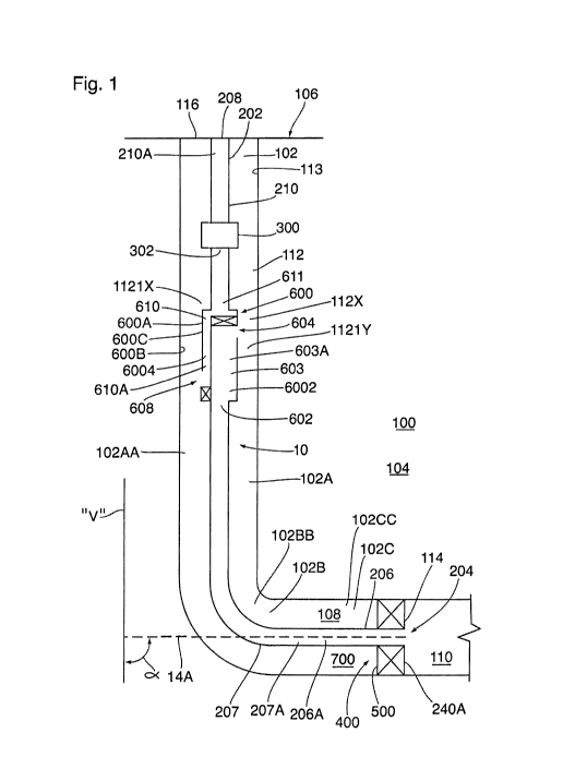
[0048] Referring to Figures 1 and 2, there are provided systems 8, with
associated
apparatuses, for producing hydrocarbons from a reservoir, such as an oil
reservoir, within a
subterranean formation 100, when reservoir pressure within the oil reservoir
is insufficient to
conduct hydrocarbons to the surface 106 through a wellbore 102.
[0049] The wellbore 102 can be straight, curved, or branched. The
wellbore 102 can
have various wellbore portions. A wellbore portion is an axial length of a
wellbore 102. A
wellbore portion can be characterized as "vertical" or "horizontal" even
though the actual axial
orientation can vary from true vertical or true horizontal, and even though
the axial path can tend
to "corkscrew" or otherwise vary. The term "horizontal", when used to describe
a wellbore
portion, refers to a horizontal or highly deviated wellbore portion as
understood in the art, such
as, for example, a wellbore portion having a longitudinal axis that is between
about 70 and about
110 degrees from vertical. The term "vertical", when used to describe a
wellbore portion, refers
to a vertical or highly deviated vertical portion as understood in the art,
such as, for example, a
wellbore portion having a longitudinal axis that is less than about 20 degrees
from the vertical.
[0050] "Reservoir fluid" is fluid that is contained within an oil
reservoir. Reservoir fluid
may be liquid material, gaseous material, or a mixture of liquid material and
gaseous material.
In some embodiments, for example, the reservoir fluid includes water and
hydrocarbons, such as
oil, natural gas condensates, or any combination thereof
[0051] Fluids may be injected into the oil reservoir through the wellbore
to effect
stimulation of the reservoir fluid. For example, such fluid injection is
effected during hydraulic
fracturing, water flooding, water disposal, gas floods, gas disposal
(including carbon dioxide
sequestration), steam-assisted gravity drainage ("SAGD") or cyclic steam
stimulation ("CSS").
In some embodiments, for example, the same wellbore is utilized for both
stimulation and
production operations, such as for hydraulically fractured formations or for
formations subjected
CA 03050017 2019-07-12
WO 2018/129627 PCT/CA2018/050034
18
to CSS. In some embodiments, for example, different wellbores are used, such
as for formations
subjected to SAGD, or formations subjected to waterflooding.
[0052] A wellbore string 113 is employed within the wellbore 102 for
stabilizing the
subterranean formation 100. In some embodiments, for example, the wellbore
string 113 also
contributes to effecting fluidic isolation of one zone within the subterranean
formation 100 from
another zone within the subterranean formation 100.
[0053] The fluid productive portion of the wellbore 102 may be completed
either as a
cased-hole completion or an open-hole completion.
[0054] A cased-hole completion involves running wellbore casing down into
the
wellbore through the production zone. In this respect, in the cased-hole
completion, the wellbore
string 113 includes wellbore casing.
[0055] The annular region between the deployed wellbore casing and the
oil reservoir
may be filled with cement for effecting zonal isolation (see below). The
cement is disposed
between the wellbore casing and the oil reservoir for the purpose of effecting
isolation, or
substantial isolation, of one or more zones of the oil reservoir from fluids
disposed in another
zone of the oil reservoir. Such fluids include reservoir fluid being produced
from another zone
of the oil reservoir (in some embodiments, for example, such reservoir fluid
being flowed
through a production tubing string disposed within and extending through the
wellbore casing to
the surface), or injected fluids such as water, gas (including carbon
dioxide), or stimulations
fluids such as fracturing fluid or acid. In this respect, in some embodiments,
for example, the
cement is provided for effecting sealing, or substantial sealing, of flow
communication between
one or more zones of the oil reservoir and one or more others zones of the oil
reservoir (for
example, such as a zone that is being produced). By effecting the sealing, or
substantial sealing,
of such flow communication, isolation, or substantial isolation, of one or
more zones of the oil
reservoir, from another subterranean zone (such as a producing formation), is
achieved. Such
isolation or substantial isolation is desirable, for example, for mitigating
contamination of a
water table within the oil reservoir by the reservoir fluid (e.g. oil, gas,
salt water, or combinations
thereof) being produced, or the above-described injected fluids.
CA 03050017 2019-07-12
WO 2018/129627 PCT/CA2018/050034
19
[0056] In some embodiments, for example, the cement is disposed as a
sheath within an
annular region between the wellbore casing and the oil reservoir. In some
embodiments, for
example, the cement is bonded to both of the production casing and the oil
reservoir.
[0057] In some embodiments, for example, the cement also provides one or
more of the
following functions: (a) strengthens and reinforces the structural integrity
of the wellbore, (b)
prevents, or substantially prevents, produced reservoir fluid of one zone from
being diluted by
water from other zones. (c) mitigates corrosion of the wellbore casing, (d) at
least contributes to
the support of the wellbore casing, and e) allows for segmentation for
stimulation and fluid
inflow control purposes.
[0058] The cement is introduced to an annular region between the wellbore
casing and
the oil reservoir after the subject wellbore casing has been run into the
wellbore. This operation
is known as "cementing".
[0059] In some embodiments, for example, the wellbore casing includes one
or more
casing strings, each of which is positioned within the well bore, having one
end extending from
the well head. In some embodiments, for example, each casing string is defined
by jointed
segments of pipe. The jointed segments of pipe typically have threaded
connections.
[0060] Typically, a wellbore contains multiple intervals of concentric
casing strings,
successively deployed within the previously run casing. With the exception of
a liner string,
casing strings typically run back up to the surface 106. Typically, casing
string sizes are
intentionally minimized to minimize costs during well construction. Generally,
smaller casing
sizes make production and artificial lofting more challenging.
[0061] For wells that are used for producing reservoir fluid, few of
these actually produce
through wellbore casing. This is because producing fluids can corrode steel or
form undesirable
deposits (for example, scales, asphaltenes or paraffin waxes) and the larger
diameter can make
flow unstable. In this respect, a production string is usually installed
inside the last casing string.
The production string is provided to conduct reservoir fluid, received within
the wellbore, to the
wellhead 116. In some embodiments, for example. the annular region between the
last casing
string and the production tubing string may be sealed at the bottom by a
packer.
CA 03050017 2019-07-12
WO 2018/129627 PCT/CA2018/050034
[0062] To facilitate flow communication between the reservoir and the
wellbore, the
wellbore casing may be perforated, or otherwise include per-existing ports
(which may be
selectively openable, such as, for example, by shifting a sleeve), to provide
a fluid passage for
enabling flow of reservoir fluid from the reservoir to the wellbore.
[0063] In some embodiments, for example, the wellbore casing is set short
of total depth.
Hanging off from the bottom of the wellbore casing, with a liner hanger or
packer, is a liner
string. The liner string can be made from the same material as the casing
string, but, unlike the
casing string, the liner string does not extend back to the wellhead 116.
Cement may be
provided within the annular region between the liner string and the oil
reservoir for effecting
zonal isolation (see below), but is not in all cases. In some embodiments, for
example, this liner
is perforated to effect flow communication between the reservoir and the
wellbore. In this
respect, in some embodiments, for example, the liner string can also be a
screen or is slotted. In
some embodiments, for example, the production tubing string may be engaged or
stung into the
liner string, thereby providing a fluid passage for conducting the produced
reservoir fluid to the
wellhead 116. In some embodiments, for example, no cemented liner is
installed, and this is
called an open hole completion or uncemented casing completion.
[0064] An open-hole completion is effected by drilling down to the top of
the producing
formation, and then lining the wellbore (such as, for example, with a wellbore
string 113). The
wellbore is then drilled through the producing formation, and the bottom of
the wellbore is left
open (i.e. uncased), to effect flow communication between the reservoir and
the wellbore. Open-
hole completion techniques include bare foot completions, pre-drilled and pre-
slotted liners, and
open-hole sand control techniques such as stand-alone screens, open hole
gravel packs and open
hole expandable screens. Packers and casing can segment the open hole into
separate intervals
and ported subs can be used to effect flow communication between the reservoir
and the
wellbore.
[0065] Referring to Figures 1 and 2, an assembly 10 is provided for
effecting production
of reservoir fluid from the reservoir 104 of the subterranean formation 100.
[0066] In some embodiments, for example, a wellbore fluid conductor 113,
such as, for
example, the wellbore string 113 (such as, for example, the casing 113), is
disposed within the
CA 03050017 2019-07-12
WO 2018/129627 PCT/CA2018/050034
21
wellbore 102. The assembly 10 is configured for disposition within the
wellbore fluid conductor
113, such that an intermediate wellbore passage 112 is defined within the
wellbore fluid
conductor 113, between the assembly 10 and the wellbore fluid conductor 113.
In some
embodiments, for example, the intermediate wellbore passage 112 is an annular
space disposed
between the assembly 10 and the wellbore string 113. In some embodiments, for
example, the
intermediate wellbore passage 112 is defined by the space that extends
outwardly, relative to the
central longitudinal axis of the assembly 10, from the assembly 10 to the
wellbore fluid
conductor 113. In some embodiments, for example, the intermediate wellbore
passage 112
extends longitudinally to the wellhead 116, between the assembly 10 and the
wellbore string 113.
[0067] The assembly 10 includes a production string 202 that is disposed
within the
wellbore 102. The production string 202 includes a pump 300
[0068] The pump 300 is provided to, through mechanical action, pressurize
and effect
conduction of the reservoir fluid from the reservoir 104, through the wellbore
102, and to the
surface 106, and thereby effect production of the reservoir fluid. It is
understood that the
reservoir fluid being conducted uphole through the wellbore 102, via the
production string 202,
may be additionally energized by supplemental means, including by gas-lift. In
some
embodiments, for example, the pump 300 is a sucker rod pump. Other suitable
pumps 300
include screw pumps, electrical submersible pumps, and jet pumps.
[0069] The system also includes a flow diverter 600. The flow diverter
600 is provided
for, amongst other things, mitigating gas lock within the pump 300. In some
embodiments, for
example, the flow diverter 600 is disposed within a vertical portion of the
wellbore 102 that
extends to the surface 106.
[0070] In some embodiments, the flow diverter 600 includes a wellbore
string
counterpart 600B and an assembly counterpart 600C. The wellbore string 113
defines the
wellbore string counterpart 600B, and the assembly 10 defines the assembly
counterpart 600C.
The flow diverter 600 defines: (i) a reservoir fluid-conducting passage 6002
for diverted
reservoir fluid, received within the downhole wellbore space from the
reservoir 104, to a
reservoir fluid separation space 112X of the wellbore 102, with effect that a
gas-depleted
reservoir fluid is separated from the reservoir fluid within the reservoir
fluid separation space
CA 03050017 2019-07-12
WO 2018/129627 PCT/CA2018/050034
22
112X in response to at least buoyancy forces; and (ii) a gas-depleted
reservoir fluid-conducting
passage 6004 for receiving the separated gas-depleted reservoir fluid while
the separated gas-
depleted reservoir fluid is flowing in a downhole direction, and diverting the
flow of the received
gas-depleted reservoir fluid such that the received gas-depleted reservoir
fluid is conducted by
the flow diverter 600 in the uphole direction to the pump 300.
[0071] As discussed above, the wellbore 102 is disposed in flow
communication (such as
through perforations provided within the installed casing or liner, or by
virtue of the open hole
configuration of the completion), or is selectively disposable into flow
communication (such as
by perforating the installed casing, or by actuating a valve to effect opening
of a port), with the
reservoir 104. When disposed in flow communication with the reservoir 104, the
wellbore 102 is
disposed for receiving reservoir fluid flow from the reservoir 104.
[0072] The production string inlet 204 is for receiving, via the
wellbore, the reservoir
fluid flow from the reservoir. In this respect, the reservoir fluid flow
enters the wellbore 102, as
described above, and is then conducted to the production string inlet 204. The
production string
202 includes a reservoir fluid-supplying conductor 206, disposed downhole
relative to the flow
diverter 600 for conducting the reservoir fluid (such as a reservoir fluid
flow), that is being
received by the production string inlet, such that the reservoir fluid, that
is received by the inlet
204, is conducted to the flow diverter 600 via the fluid-supplying conductor
206. The production
string 202 also includes a gas-depleted reservoir fluid-producing conductor
210, disposed uphole
relative to the flow diverter 600 for conducting a gas-depleted reservoir
fluid (such as a gas-
depleted reservoir fluid flow) from the flow diverter 600 to a production
string outlet 208,
located at the wellhead 116.
[0073] It is preferable to remove at least a fraction of the gaseous
material from the
reservoir fluid flow being conducted within the production string 202, prior
to the pump suction
302, in order to mitigate gas interference or gas lock conditions during pump
operation. The
flow diverter 600, is provided to, amongst other things, perform this
function. In this respect, the
flow diverter 600 is disposed downhole relative to the pump 300 and is fluidly
coupled to the
pump suction 302, such as, for example, by an intermediate fluid conductor
that forms part of the
CA 03050017 2019-07-12
WO 2018/129627 PCT/CA2018/050034
23
fluid-producing conductor 210, such as piping. Suitable exemplary flow
diverters are described
in International Application No. PCT/CA2015/000178, published on October 1,
2015.
[0074] In some embodiments, for example, the assembly counterpart 600C
includes a
fluid diverter body 600A.
[0075] In some embodiments, for example, the flow diverter body 600A is
configured
such that the depletion of gaseous material from the reservoir fluid material,
that is effected
while the assembly 10 is disposed within the wellbore 102, is effected
externally of the flow
diverter body 600A within the wellbore 102, such as, for example, within an
uphole wellbore
space 108 of the wellbore 102.
[0076] The flow diverter body 600A includes a reservoir fluid receiver
602 for receiving
the reservoir fluid (such as, for example, in the form of a reservoir fluid
flow) that is being
conducted (e.g. flowed), via the fluid-supplying conductor 206 of the
production string 202, from
the production string inlet 204. In some embodiments, for example, the fluid-
supplying
conductor 206 extends from the inlet 204 to the receiver 602. In this respect,
the fluid-supplying
conductor 206 is fluidly coupled to the inlet 204.
[0077] The flow diverter body 600A also includes a reservoir fluid
discharge
communicator 604 that is fluidly coupled to the reservoir fluid receiver 602
via a reservoir fluid-
conductor 603. In this respect, the reservoir fluid conductor 603 defines at
least a portion of the
reservoir fluid-conducting passage 6002.
[0078] The reservoir fluid conductor 603 defines one or more reservoir
fluid conductor
passages 603A. In some of the embodiments described below, for example, the
one or more
reservoir fluid-conducting passages 603A. The reservoir fluid discharge
communicator 604 is
configured for discharging reservoir fluid (such as, for example, in the form
of a flow) that is
received by the reservoir fluid receiver 602 and conducted to the reservoir
fluid discharge
communicator 604 via the reservoir fluid conductor 603. In some embodiments,
for example,
the reservoir fluid discharge communicator 604 is disposed at an opposite end
of the flow
diverter body 600A relative to the reservoir fluid receiver 602.
CA 03050017 2019-07-12
WO 2018/129627 PCT/CA2018/050034
24
[0079]
The flow diverter body 600A also includes a gas-depleted reservoir fluid
receiver
608 for receiving a gas-depleted reservoir fluid (such as, for example, in the
form of a flow),
after gaseous material has been separated from the reservoir fluid (for
example, a reservoir fluid
flow), that has been discharged from the reservoir fluid discharge
communicator 604, in response
to at least buoyancy forces. In this respect, the gas-depleted reservoir fluid
receiver 608 and the
reservoir fluid discharge communicator 604 are co-operatively configured such
that the gas-
depleted reservoir fluid receiver 608 is disposed for receiving a gas-depleted
reservoir fluid flow,
after gaseous material has been separated from the received reservoir fluid
flow that has been
discharged from the reservoir fluid discharge communicator 604, in response to
at least
buoyancy forces.
In some embodiments, for example, the reservoir fluid discharge
communicator 604 is disposed at an opposite end of the flow diverter body 600A
relative to the
gas-depleted reservoir fluid receiver 608.
[0080]
The flow diverter body 600A also includes a gas-depleted reservoir fluid
conductor 610 that defines a gas-depleted reservoir fluid-conducting passage
610A configured
for conducting the gas-depleted reservoir fluid (for example, a gas-depleted
reservoir fluid flow),
received by the receiver 608, to the gas-depleted reservoir fluid discharge
communicator 604. In
some embodiments, for example, the gas-depleted reservoir fluid discharge
communicator 611 is
disposed at an opposite end of the flow diverter body 600A relative to the gas-
depleted reservoir
fluid receiver 608. The gas-depleted reservoir fluid discharge communicator
611 is configured
for fluid coupling to the pump 300, wherein the fluid coupling is for
supplying the pump 300
with the gas-depleted reservoir fluid received by the receiver 610 and
conducted through at least
the gas-depleted reservoir fluid conductor 610. In this respect, the gas-
depleted reservoir fluid-
conducting passage 610A defines at least a portion of the gas-depleted
reservoir fluid-conducting
passage 6004.
[0081]
Referring to Figure 2, in some embodiments, for example, the reservoir fluid
discharge communicator 604 is oriented such that, a ray (see, for example ray
604A), that is
disposed along the central longitudinal axis of the reservoir fluid discharge
communicator, is
disposed in an uphole direction at an acute angle of less than 30 degrees
relative to the central
longitudinal axis of the wellbore portion within which the flow diverter body
600A is disposed.
CA 03050017 2019-07-12
WO 2018/129627 PCT/CA2018/050034
[0082] Again referring to Figure 2, in some embodiments, for example, the
reservoir
fluid discharge communicator 604 is oriented such that, a ray (see, for
example ray 604A), that is
disposed along the central longitudinal axis of the reservoir fluid discharge
communicator 604, is
disposed in an uphole direction at an acute angle of less than 30 degrees
relative to the vertical
(which includes disposition of the ray 604A along a vertical axis).
[0083] In some embodiments, for example, the flow diverter body 600A
includes the
reservoir fluid receiver 602 (such as, for example, in the form of one or more
ports), the reservoir
fluid discharge communicator 604 (such as, for example, in the form of one or
more ports), and
the reservoir fluid conductor 603 (such as, for example, in the form of one or
more fluid passages
603A, such as, for example, a network of fluid) for fluidly coupling the
receiver 602 and the
discharge communicator 604. The flow diverter body 600A also includes the gas-
depleted
reservoir fluid receiver 608 (such as, for example, in the form of one or more
ports), gas-depleted
reservoir fluid discharge communicator 611 (such as, for example, in the form
of one or more
ports), and the gas-depleted reservoir fluid conductor 610 (such as, for
example, in the form of a
fluid passage or a network of fluid passages) for fluidly coupling the
receiver 608 to the
discharge communicator 611.
[0084] The assembly counterpart 600C also includes a wellbore sealed
interface effector
400 configured for interacting with a wellbore feature for defining a wellbore
sealed interface
500 within the wellbore 102, between: (a) an uphole wellbore space 108 of the
wellbore 102, and
(b) a downhole wellbore space 110 of the wellbore 102, while the assembly 10
is disposed within
the wellbore 102.
[0085] In some embodiments, for example, the disposition of the sealed
interface 500 is
such that flow communication, via the intermediate wellbore passage 112,
between an uphole
wellbore space 108 and a downhole wellbore space 110 (and across the sealed
interface 500), is
prevented, or substantially prevented. In some embodiments, for example, the
disposition of the
sealed interface 500 is such that fluid flow, across the sealed interface 500,
in a downhole
direction, from the uphole wellbore space 108 to the downhole wellbore space
110, is prevented,
or substantially prevented.
CA 03050017 2019-07-12
WO 2018/129627 PCT/CA2018/050034
26
[0086] In such embodiments, for example, the disposition of the sealed
interface 500 is
effected by the combination of at least: (i) a sealed, or substantially
sealed, disposition of the
wellbore string 113 relative to a polished bore receptacle 114 (such as that
effected by a packer
240A disposed between the wellbore string 113 and the polished bore receptacle
114), and (ii) a
sealed, or substantially sealed, disposition of the fluid-supplying conductor
206 relative to the
polished bore receptacle 114. In this respect, the sealed interface 500
functions to prevent, or
substantially prevented, reservoir fluid flow, that is received within the
wellbore 102 (that is
lined with the wellbore string 113), from bypassing the reservoir fluid
receiver 602, and, as a
corollary, the reservoir fluid is directed to the reservoir fluid receiver 602
for receiving by the
reservoir fluid receiver 602. As well, the sealed interface 500 functions to
prevent, or
substantially prevented, gas-depleted reservoir fluid flow, that has been
separated from the
reservoir fluid discharged into the wellbore 102 from the discharge
communicator 604, from
bypassing the gas-depleted reservoir fluid receiver 608 and, as a corollary,
the gas-depleted
reservoir fluid is directed to the gas-depleted reservoir fluid receiver 608
for receiving by the
gas-depleted reservoir fluid receiver 608.
[0087] In some embodiments, for example, the sealed, or substantially
sealed, disposition
of the fluid-supplying conductor 206 relative to the polished bore receptacle
114 is effected by a
latch seal assembly. A suitable latch seal assembly is a WeatherfordTM Thread-
Latch Anchor
Seal AssemblyTM.
[0088] In some embodiments, for example, the sealed, or substantially
sealed, disposition
of the downhole fluid-supplying conductor 206 relative to the polished bore
receptacle 114 is
effected by one or more o-rings or seal-type Chevron rings. In this respect,
the sealing interface
effector 400 includes the o-rings, or includes the seal-type Chevron rings.
[0089] In some embodiments, for example, the sealed, or substantially
sealed, disposition
of the fluid-supplying conductor 206 relative to the polished bore receptacle
114 is disposed in
an interference fit with the polished bore receptacle. In some of these
embodiments, for
example, the fluid-supplying conductor 206 is landed or engaged or "stung"
within the polished
bore receptacle 114.
CA 03050017 2019-07-12
WO 2018/129627 PCT/CA2018/050034
27
[0090] The above-described disposition of the wellbore sealed interface
500 provide for
conditions which minimize solid debris accumulation in the joint between the
downhole fluid-
supplying conductor 206 and the polished bore receptacle 114 or in the joint
between the
polished bore receptacle 114 and the wellbore string 113. By providing for
conditions which
minimize solid debris accumulation within the joint, interference to movement
of the separator
relative to the liner, or the casing, as the case may be, which could be
effected by accumulated
solid debris, is mitigated.
[0091] Referring to Figure 1, in some embodiments, for example, the
sealed interface
500 is disposed within a section of the wellbore 102 whose axis 14A is
disposed at an angle "a"
of at least 60 degrees relative to the vertical "V". In some of these
embodiments, for example,
the sealed interface 500 is disposed within a section of the wellbore whose
axis is disposed at an
angle "a" of at least 85 degrees relative to the vertical "V". In this
respect, disposing the sealed
interface 500 within a wellbore section having such wellbore inclinations
minimizes solid debris
accumulation at the sealed interface 500.
[0092] In some embodiments, for example, the flow diverter body 600, the
sealed
interface effector 400, and the reservoir fluid conductor 206, are co-
operatively configured such
that, while the assembly 10 is disposed within the wellbore string 113 such
that the sealed
interface 500 is defined, and the reservoir fluid-supplying conductor 206 is
receiving reservoir
fluid from the downhole wellbore space 110 that has been received within the
downhole
wellbore space 110 from the subterranean formation 100:
the reservoir fluid is conducted to the reservoir fluid receiver 602 via the
reservoir fluid-
supplying conductor 206;
the reservoir fluid is conducted to the reservoir fluid discharge communicator
604 by the
reservoir fluid conductor 603 and discharged to the reservoir fluid separation
space 112X of the
uphole wellbore space 108;
within the reservoir fluid separation space 112X, a gas-depleted reservoir
fluid is
separated from the discharged reservoir fluid, in response to at least
buoyancy forces, such that
the gas-depleted reservoir fluid is obtained;
CA 03050017 2019-07-12
WO 2018/129627 PCT/CA2018/050034
28
the separated gas-depleted reservoir fluid is conducted to the gas-depleted
reservoir fluid
receiver 608 via the intermediate wellbore passage 112, and the received gas-
depleted reservoir
fluid is conducted from the gas-depleted reservoir fluid receiver 608 to the
pump 300 via at least
the conductor 610 and the gas-depleted reservoir fluid discharge communicator
611.
[0093] In this respect, in such embodiments, for example, at least a
portion of the space
within the intermediate wellbore space 112, between the reservoir fluid
discharge communicator
604 and the gas-depleted reservoir fluid receiver 608, defines at least a
portion of the gas-
depleted reservoir fluid-conducting passage 6004.
[0094] Once received by the pump 300, the gas-depleted reservoir fluid is
pressurized by
the pump 300 and conducted to the surface via the reservoir fluid-producing
conductor 210.
[0095] Also, the separation of gaseous material from the reservoir fluid
is with effect that
a liquid-depleted reservoir fluid is obtained and is conducted uphole (in the
gaseous phase, or at
least primarily in the gaseous phase with relatively small amounts of
entrained liquid) via the
intermediate wellbore passage 112 that is disposed between the assembly 10 and
the wellbore
string 113 (see above).
[0096] The reservoir fluid produced from the subterranean formation 100,
via the
wellbore 102, including the gas-depleted reservoir fluid, the liquid-depleted
reservoir material, or
both, may be discharged through the wellhead 116 to a collection facility,
such as a storage tank
within a battery.
[0097] In some embodiments, for example, the flow diverter body 600A is
configured
such that the gas-depleted reservoir fluid receiver 608 is disposed downhole
relative to (such as,
for example, vertically below) the reservoir fluid discharge communicator 604,
with effect that
the separated gas-depleted reservoir fluid is conducted in a downhole
direction to the gas-
depleted reservoir fluid receiver 608.
[0098] In some embodiments, for example, separation of gaseous material,
from the
reservoir fluid that is being discharged from the reservoir fluid discharge
communicator 604, is
effected within an uphole-disposed space 1121X of the intermediate wellbore
passage 112, the
uphole-disposed space 1121X being disposed uphole relative to the reservoir
fluid discharge
CA 03050017 2019-07-12
WO 2018/129627 PCT/CA2018/050034
29
communicator 604. In this respect, in some embodiments, for example, the
reservoir fluid
separation space 112X includes the uphole-disposed space 1121X.
[0099] In some embodiments, for example, a flow diverter body-defined
intermediate
wellbore passage portion 1121Y of the intermediate wellbore passage 112 is
disposed within a
space between the flow diverter body 600A and the wellbore string 113, and
effects flow
communication between the reservoir fluid discharge communicator 604 and the
gas-depleted
reservoir fluid receiver 608 for effecting conducting of the gas-depleted
reservoir fluid to the
gas-depleted reservoir fluid receiver 608. In this respect, in such
embodiments, for example, the
flow diverter body-defined intermediate wellbore passage portion 1121Y defines
at least a
portion of the gas-depleted reservoir fluid-conducting passage 6004.
[00100] In some embodiments, for example, the space between the flow
diverter body
600A and the wellbore string 113, within which the flow diverter body-defined
intermediate
wellbore passage portion 1121Y is disposed, is an annular space. In some
embodiments, for
example, the flow diverter body-defined intermediate space 1121Y is defined by
the entirety, or
the substantial entirety, of the space between the flow diverter body 600A and
the wellbore string
113. In some embodiments, for example, separation of gaseous material, from
the reservoir fluid
that is discharged from the reservoir fluid discharge communicator 604, is
effected within the
flow diverter body-defined intermediate wellbore passage portion 1121Y. In
this respect, in
some embodiments, for example, at least a portion of the reservoir fluid
separation space 112X is
co-located with at least a portion of the flow diverter body-defined
intermediate wellbore
passage portion 1121Y.
[00101] In some embodiments, for example, the separation of gaseous
material, from the
reservoir fluid that is being discharged from the reservoir fluid discharge
communicator 604, is
effected within both of the uphole-disposed space 1121X and the flow diverter
body-defined
intermediate wellbore passage portion 1121Y. In this respect, in some
embodiments, for
example, the reservoir fluid is discharged from the reservoir fluid discharge
communicator 604
into the uphole wellbore space 1121X, and, in response to at least buoyancy
forces, the gaseous
material is separated from the discharged reservoir fluid, while the reservoir
fluid is being
conducted downhole, from the uphole-disposed space 1121X, through the flow
diverter body-
CA 03050017 2019-07-12
WO 2018/129627 PCT/CA2018/050034
defined intermediate wellbore passage portion 1121Y, and to the gas-depleted
reservoir fluid
receiver 608. In this respect, in some embodiments, for example, the uphole-
disposed space
1121X is merged with the flow diverter body-defined intermediate wellbore
passage portion
1121Y
[00102] In some embodiments, for example, the reservoir fluid separation
space 112X
spans a continuous space extending from the assembly to the wellbore string
113, and the
continuous space extends outwardly relative to the central longitudinal axis
of the assembly 10.
[00103] In some embodiments, for example, the reservoir fluid separation
space 112X
spans a continuous space extending from the assembly to the wellbore string
113, and the
continuous space extends outwardly relative to the central longitudinal axis
of the wellbore 102.
[00104] In some embodiments, for example, the reservoir fluid separation
space 112X is
disposed within a vertical portion of the wellbore 102 that extends to the
surface 106.
[00105] In some embodiments, for example, the ratio of the minimum cross-
sectional flow
area of the reservoir fluid separation space 112X to the maximum cross-
sectional flow area of
the fluid passage 206A defined by the reservoir fluid-supplying conductor 206
is at least about
1.5.
[00106] In some embodiments, for example, the space, between: (a) the gas-
depleted
reservoir fluid receiver 608 of the flow diverter body 600A, and (b) the
sealed interface 500,
defines a sump 700 for collection of solid particulate that is entrained
within fluid being
discharged from the reservoir fluid discharge communicator 604 of the flow
diverter body 600A,
and the sump 700 has a volume of at least 0.1 m3. In some embodiments, for
example, the
volume is at least 0.5 m3. In some embodiments, for example, the volume is at
least 1.0 m3. In
some embodiments, for example, the volume is at least 3.0 m3.
[00107] By providing for the sump 700 having the above-described
volumetric space
characteristic, and/or the above-described minimum separation distance
characteristic, a suitable
space is provided for collecting relative large volumes of solid debris, from
the gas-depleted
reservoir fluid being flowed downwardly to the gas-depleted reservoir fluid
receiver 608, such
that interference by the accumulated solid debris with the production of oil
through the system is
CA 03050017 2019-07-12
WO 2018/129627 PCT/CA2018/050034
31
mitigated. This increases the run-time of the system before any maintenance is
required. As
well, because the solid debris is deposited over a larger area, the propensity
for the collected
solid debris to interfere with movement of the flow diverter body 600A within
the wellbore 102,
such as during maintenance (for example, a workover) is reduced.
[00108] As above-described, the reservoir fluid-producing conductor 210
extends from the
gas-depleted reservoir fluid discharge communicator 611 to the wellhead 116
for effecting flow
communication between the discharge communicator 611 and the earth's surface
106, such as,
for example, a collection facility located at the earth's surface 106, and
defines a fluid passage
210A. In some embodiments, for example, reservoir fluid-supplying conductor
206 defines a
fluid passage 206A. The cross-sectional flow area of the fluid passage 210A is
greater than the
cross-sectional flow area of the fluid passage 206A. In some embodiments, for
example, the
ratio of the cross-sectional flow area of the fluid passage 210A to the cross-
sectional flow area of
the fluid passage 206A is at least 1.1, such as, for example, at least 1.25,
such as, for example, at
least 1.5.
[00109] In some embodiments, for example, the reservoir fluid-supplying
conductor 206
includes a velocity string 207, and, in some embodiments, for example, the
entirety, or the
substantial entirety of the reservoir fluid-supplying conductor 206 is a
velocity string 207. In
some embodiments, for example, the velocity string 207 extends from the
production string inlet
204. In some embodiments, for example, at least 25% of the length of the fluid-
supplying
conductor 206, as measured along the central longitudinal axis of the fluid-
supplying conductor
206, is a velocity string 207. In some embodiments, for example, the length of
the velocity
string 207, measured along the central longitudinal axis of the velocity
string, is at least 20 feet.
In some embodiments, for example, the velocity string 207 includes a fluid
passage 207A, and
the cross-sectional area of the entirety of the fluid passage 207A is less
than the cross-sectional
area of the entirety of the fluid passage 210A of the fluid-producing
conductor 210. In this
respect, in some embodiments, for example, the maximum cross-sectional area of
the fluid
passage 207A is less than the minimum cross-sectional area of the fluid
passage 210A. In some
embodiments, for example, the maximum cross-sectional area of the fluid
passage 207A is less
than about 75% (such as, for example 50%) of the minimum cross-sectional area
of at least 75%
(such as, for example, at least 80%, such as, for example, at least 85%, such
as, for example, at
CA 03050017 2019-07-12
WO 2018/129627 PCT/CA2018/050034
32
least 90%, such as, for example, at least 95%) of the length of the fluid-
supplying conductor 206,
as measured along the central longitudinal axis of the fluid-supplying
conductor 206. In some
embodiments, for example, the length of the fluid-supplying conductor 206, as
measured along
the central longitudinal axis of the fluid-supplying conductor 206, is at
least 500 feet, such as, for
example, at least 750 feet, such as, for example at least 1000 feet.
[00110] In some embodiments, for example, the flow diverter 600 is
disposed uphole of a
horizontal section 102C of the wellbore 102, such as, in some embodiments, for
example, within
a vertical section 102A, or, in some embodiments, for example, within a
transition section 102B.
[00111] . In some embodiments, for example, the central longitudinal axis
of the passage
102CC of the horizontal section 102C is disposed along an axis that is between
about 70 and
about 110 degrees relative to the vertical "V", the central longitudinal axis
of the passage 102AA
of the vertical section 102A is disposed along an axis that is less than about
20 degrees from the
vertical "V", and the transition section 102B is disposed between the sections
102A and 102C.
In some embodiments, for example, the transition section 102B joins the
sections 102A and
102C. In some embodiments, for example, the vertical section 102A extends from
the transition
section 102B to the surface 106.
[00112] In some of these embodiments, for example, the reservoir fluid-
supplying
conductor 206 extends from the flow diverter 600, in a downhole direction,
into the horizontal
section 102C, such that the inlet 204 is disposed within the horizontal
section 102C.
[00113] Referring to Figures 3 and 4, an anchor 620 is mounted to the flow
diverter 600
for effecting coupling (such as, for example, anchoring) of the assembly 10 to
the wellbore
string. In some embodiments, for example, the anchor 620 is an industry
standard tubing anchor.
[00114] In some embodiments, for example, the anchor 620 is disposed such
that there is
an absence, or substantial absence, of opposition to flow of a gaseous
material, that has been
separated from the reservoir fluid within the reservoir fluid separation space
112X in response to
at least buoyancy forces, by the anchor 620.
[00115] In some embodiments, for example, the anchor 620 is disposed such
that fluid
communication, via one or more flowpaths 112A defined between the anchor 620
and the
CA 03050017 2019-07-12
WO 2018/129627 PCT/CA2018/050034
33
wellbore fluid conductor 114 (see Figure 3) is defined between the reservoir
fluid discharge
communicator 604 and the gas-depleted reservoir fluid inlet port 608.
[00116] Reservoir fluid that is being conducted through the transition
section 102B is
particularly susceptible to liquid loading because of the change in direction,
to the reservoir fluid
being conducted through the transition section 102B, that is urged by virtue
of the configuration
of transition section 102B. To mitigate liquid loading, the reservoir fluid-
supplying conductor
206 is configured such that the reservoir fluid is being conducted through the
transition section
102B at a sufficiently high speed. In this respect, and referring to Figure 5,
the reservoir fluid-
supplying conductor 206 includes a vertical section-disposed portion 2061,
that is disposed in the
vertical section 102A, a transition section-disposed portion 2062, that is
disposed in the
transition section 102B, and a horizontal-section disposed portion 2063, that
is disposed in the
horizontal section 102C, A cross-sectional area of the fluid passage 2062A of
the transition
section-disposed portion 2062 is less than both of: (i) a cross-sectional area
of the fluid passage
2061A of the vertical section-disposed portion 2061, and (ii) a cross-
sectional area of the fluid
passage 2063A of the horizontal section-disposed portion 2063. In some
embodiments, for
example, the central longitudinal axis of the fluid passage 2063A of the
horizontal section-
disposed portion 2063 is disposed along an axis that is between about 70 and
about 110 degrees
relative to the vertical "V", the central longitudinal axis of the fluid
passage 2063A of the
vertical section-disposed portion 2063 is disposed along an axis that is less
than about 20 degrees
from the vertical "V", and the transition-section disposed portion 2062 is
disposed between the
portions 2061 and 2063. In some embodiments, for example, the transition-
section disposed
portion 2062 joins the portions 2061 and 2063. In some embodiments, for
example, the vertical
section-disposed portion 2061 extends from the transition section-disposed
portion 2062 to the
surface 106.
[00117] In some embodiments, for example, the ratio of the minimum cross-
sectional area
of the fluid passage 2063A of the horizontal section-disposed portion 2063 to
the maximum
cross-sectional area of the fluid passage 2062A of the transition section-
disposed portion 2062 is
at least 1.1, such as, for example, at least 1.2, such as, for example at
least 1.25. In some
embodiments, for example, the ratio of the minimum cross-sectional area of the
fluid passage
2061A of the vertical section-disposed portion 2061 to the maximum cross-
sectional area of the
CA 03050017 2019-07-12
WO 2018/129627 PCT/CA2018/050034
34
fluid passage 2062A of the transition section-disposed portion 2062 is at
least 1.1, such as, for
example, at least 1.2, such as, for example at least 1.25. In some
embodiments, for example, the
ratio of the minimum cross-sectional area of the fluid passage 2063A of the
horizontal section-
disposed portion 2063 to the maximum cross-sectional area of the fluid passage
2062A of the
transition section-disposed portion 2062 is at least 1.1, such as, for
example, at least 1.2, such as,
for example at least 1.25, and also the ratio of the minimum cross-sectional
area of the fluid
passage 2061A of the vertical section-disposed-portion 2061 to the maximum
cross-sectional
area of the fluid passage 2062A of the transition section disposed portion
2062 is at least 1.1,
such as, for example, at least 1.2, such as, for example at least 1.25.
[00118] In some embodiments, for example, the transition section-disposed
portion 2062
extends along a curved path. In some embodiments, for example, the length of
the transition
section-disposed portion 2062, as measured along the central longitudinal axis
of the section-
disposed portion 2062, is at least 50 feet, such as, for example, at least 100
feet, such as, for
example, at least 200 feet, such as, for example, at least 300 feet, such as,
for example, at least
400 feet, such as, for example, at least 500 feet.
[00119] In some embodiments, for example, the vertical section-disposed
portion 2061
includes an operative vertical section-disposed portion and the operative
vertical section-
disposed portion has a length, measured along the central longitudinal axis of
the fluid passage
2061A of the vertical section-disposed portion 2061, that is at least 50%
(such as, for example, at
least 75%, such as, for example, 100%) of the length of the vertical section-
disposed portion
2061 measured along the central longitudinal axis of the fluid passage 2061A
of the vertical
section-disposed portion 2061, the transition section-disposed portion 2062
includes an operative
transition section-disposed portion and the operative transition section-
disposed portion has a
length, measured along the central longitudinal axis of the fluid passage
2062A of the transition
section-disposed portion 2062, that is at least 50% (such as, for example, at
least 75%, such as,
for example, 100%) of the length of the transition section-disposed portion
2062 measured along
the central longitudinal axis of the fluid passage 2062A of the transition
section-disposed portion
2062, and the horizontal section-disposed portion 2061 includes an operative
horizontal section-
disposed portion and the operative horizontal section-disposed portion has a
length, measured
along the central longitudinal axis of the fluid passage 2061C of the
horizontal section-disposed
CA 03050017 2019-07-12
WO 2018/129627 PCT/CA2018/050034
portion 2061C, that is at least 50% (such as, for example, at least 75%, such
as, for example,
100%) of the length of the horizontal section-disposed portion 2061 measured
along the central
longitudinal axis of the fluid passage 2061A of the horizontal section-
disposed portion 2061, and
the ratio of the minimum cross-sectional area of the fluid passage 2061A of
the operative
horizontal section-disposed portion 2061 to the maximum cross-sectional area
of the fluid
passage 2062A of the operative transition section-disposed portion is at least
1.1, such as, for
example, at least 1.2, such as, for example at least 1.25. In some
embodiments, for example, the
ratio of the minimum cross-sectional area of the fluid passage 2061A of the
operative vertical
section-disposed portion to the maximum cross-sectional area of the fluid
passage 2062A of the
operative transition section disposed portion is at least 1.1, such as, for
example, at least 1.2,
such as, for example at least 1.25. In some embodiments, for example, the
ratio of the minimum
cross-sectional area of the fluid passage 2063A of the operative horizontal
section-disposed
portion to the maximum cross-sectional area of the fluid passage 2062A of the
operative
transition section disposed portion is at least 1.1, such as, for example, at
least 1.2, such as, for
example at least 1.25, and also the ratio of the minimum cross-sectional area
of the fluid passage
2061A of the operative vertical section-disposed portion to the maximum cross-
sectional area of
the fluid passage 2062A of the transition section-disposed portion is at least
1.1, such as, for
example, at least 1.2, such as, for example at least 1.25. In some
embodiments, for example, the
operative transition section-disposed portion extends along a curved path.
[00120] Referring to Figures 6, 7A, and 7B, the reservoir fluid-supplying
conductor 206
includes an internal surface 206B that defines the fluid passage 206A for
conducting the
reservoir fluid that is received by the inlet 204. In some embodiments, for
example, the internal
surface 206B is that of the velocity string 207 such that the fluid passage
206A is defined by the
fluid passage 207A.
[00121] In some embodiments, for example, the internal surface 206B of at
least a section
of the reservoir fluid-supplying conductor 206 is contoured with effect that
reservoir fluid being
conducted through the fluid passage 206A has a swirl flow component.
CA 03050017 2019-07-12
WO 2018/129627 PCT/CA2018/050034
36
[00122] In some embodiments, for example, the internal surface 206B of at
least a section
of the reservoir fluid-supplying conductor 206 is contoured with effect that,
while a reservoir
fluid is being flowed through the fluid passage 206A, a swirl in the flow is
induced.
[00123] In some embodiments, for example, the internal surface 206B of at
least a section
of the reservoir fluid-supplying conductor 206 is contoured for generating a
swirl flow in
reservoir fluid being conducted through the fluid passage 206A.
[00124] In some embodiments, for example, the swirl is disposed about the
central
longitudinal axis of the fluid passage 206A.
[00125] In some embodiments, for example, the contouring is defined by a
rifled groove
206C, such as, for example, a helical rifled groove. In some embodiments, for
example, the
rifled groove has a minimum depth of at least 0.1 cm. In some embodiments, for
example, the
pitch of the rifled groove is between 30 degrees to 60 degrees, such as, for
example, between 40
degrees and 55 degrees.
[00126] In some embodiments, for example, the contouring is defined by a
plurality of
spaced apart vanes extending into the fluid passage 206A.
[00127] In some embodiments, for example, the at least a section of the
reservoir fluid-
supplying conductor 206 (i.e. the "contoured portion section 206C"), whose
internal surface
206B is contoured in any one of the configuration described above, defines at
least 10% (such as,
for example, at least 25%, such as, for example, at least 50%) of the total
length of the fluid
passage 206A as measured along the central longitudinal axis 2060D of the
fluid passage 206A.
In some embodiments, for example, the contoured portion section 206C has a
length of at least
feet, as measured along the central longitudinal axis of the fluid passage
206A. In some
embodiments, for example, the contoured portion section 206C has a length of
at least 25 feet, as
measured along the central longitudinal axis of the fluid passage 206A. In
some embodiments,
for example, the contoured portion section 206C has a length of at least 50
feet as measured
along the central longitudinal axis of the fluid passage 206A. In some
embodiments, for
example, the contoured portion section 206C has a length of at least 100 feet
as measured along
the central longitudinal axis of the fluid passage 206A.
CA 03050017 2019-07-12
WO 2018/129627 PCT/CA2018/050034
37
[00128] It is desirable to avoid slug flow through the reservoir fluid-
supplying conductor
206, as this results in liquid loading. Liquid loading reduces recovery from
the well. By
enabling swirl flow, slug flow through the reservoir fluid-supplying conductor
206 is suppressed.
[00129] In some embodiments, for example, the internal surface 206B of the
contoured
portion section 206D is defined by a polymeric material liner, such that the
contoured portion
section 206D is lined with polymeric material, and such that the contoured
portion section 206D
is defined by a polymeric material-lined fluid conductor. By integrating the
polymeric material
liner, standard tubing (configured according to specifications the American
Petroleum Institute
("API")) can be used for the conductor 206, and the cross-sectional flow of
the standard tubing is
attenuated by the liner to facilitate flow of the reservoir fluid at a desired
speed. In this respect,
in some embodiments, for example, the contouring is of the polymeric material
liner. In some
embodiments, for example, the polymeric material includes plastic material.
[00130] In some embodiments, for example, the reservoir fluid-supplying
conductor 206
includes two or more spaced-apart contoured portion sections 206D. The
contoured portion
sections 206D are co-operatively disposed such that a desired swirl flow
condition is effectible
within the fluid passage 206A.
[00131] Referring to Figure 8, 9, 10, 11A, 11B, 11C, 12A, 12B, 12C, and
12D, in some
embodiments, for example, the reservoir fluid supplying conductor 206 includes
a fluid
conductor module 220. In some embodiments, for example, the reservoir fluid
supplying
conductor 206 includes a plurality of fluid conductor modules 220, and each
one of the modules
220, independently, has a configuration of the fluid conductor 220. In some
embodiments, for
example, the modules 220 are connected end-to-end. In some embodiments, for
example, at
least some of the modules 220 are spaced apart from one another. Each one of
the modules,
independently, functions as a fluid conductor. Each one of the modules 220,
independently,
includes a module inlet 222 and a module outlet 224 and is configured for
conducting reservoir
fluid, received at the module inlet 222, from the module inlet 222 to the
module outlet 224.
[00132] Each one of the modules 220, independently, also includes, a first
tubing 226, a
second tubing 228, and a sealing member 230.
CA 03050017 2019-07-12
WO 2018/129627 PCT/CA2018/050034
38
[00133] The second tubing 228 is disposed within the first tubing 226 such
that an
intermediate space 232 is defined between the first tubing 226 and the second
tubing 228. In
some embodiments, for example, the disposition of the second tubing 228 within
the first tubing
226 is such that the second tubing 228 is nested within the first tubing 226.
In some
embodiments, for example, the intermediate space 232 is an annular space.
[00134] A sealed interface 230 is defined between the first tubing 226 and
the second
tubing 228. In some embodiments, for example, the sealed interface 230 is
effected by one or
more sealing members that are retained within the intermediate space 232.
[00135] Referring to Figures 11A, 11B and 11C, in this respect, in some
embodiments, the
sealed interface is effected by a ring 240 that is inserted and retained
within the intermediate
space 232 and couples the first and second tubing 226, 228.. The ring 240
includes a pair of
sealing members 230A, 230B. The sealing member 230A is retained within a
groove 240A
provided on an outermost surface 240B of the ring 240, and is disposed in
sealing, or
substantially sealing, engagement with the first tubing 226, while the sealing
member 230B is
retained within a groove 240C provided on an internal surface 240D of the ring
240, and is
disposed in sealing, or substantially sealing, engagement with the second
tubing 228. The ring
240 is disposed in an interference fit relationship relative to both of the
first tubing 226 and the
second tubing 228. The ring 240 includes an outwardly flared lip 242 that is
engageable to the
first tubing 226. The ring 240 is integrated into the intermediate space 232
by insertion within
the intermediate space 232 in a downhole direction while oriented with the
flared lip 242
extending outwardly in the uphole direction. While moving in the downhole
direction, the lip
242, due to its resiliency, is pressed inwardly and does not substantially
interfere with movement
of the ring 240 in the downhole direction. Upon desired positioning of the
sealing members
230A, 230B, a force is applied to the ring 240 in an uphole direction, and the
flared lip 242,
while defining the sealed interface between the first tubing 226 and the
second tubing 228.
[00136] An alternative ring 2401 is illustrated in Figures 12A, 12B, 12C
and 12D. In this
embodiment, the ring 2401 includes a plurality of grippers 2402 that are
biased outwardly,
relative to the central longitudinal axis of the ring 2401, by resilient
members 2404. In some
embodiments, for example, the resilient members 2404 are in the form of collet
springs (for
CA 03050017 2019-07-12
WO 2018/129627 PCT/CA2018/050034
39
example, beam springs), that are separated by slots 2405. In some embodiments,
for example, a
gripper 2402 is disposed on a respective collet spring 2404. In some
embodiments, for example,
the gripper 2402 is defined as a protuberance extending from the collet spring
2404. In some
embodiments, for example, the collet springs 2404 are configured for a limited
amount of
compression in response to a compressive force applied inwardly relative to a
central
longitudinal axis of the ring 2401, as the ring 2401 is being inserted into
the intermediate space
232 in a downhole direction. Each one of the grippers 2402 extends outwardly
from the
respective collet spring 2404, relative to the central longitudinal axis of
the ring 2401, and
terminates at a tip 2406 (such as, for example, a sharp tip) configured to
exert a gripping force on
the first tubing 226. Extension of the gripper 2402 from the collet spring
2404 is tapered in a
downhole direction. This, in combination with the resiliency of the collet
springs 2404, enables
the ring 2401 to be inserted into the intermediate space 232 in a downhole
direction, without
substantial interference by the gripper 2402. Upon desired positioning of the
sealing members
230A, 230B (disposed in grooves 2401A, C), a force is applied to the ring 2401
in an uphole
direction, and the grippers 2402 become disposed in gripping engagement with
the first tubing
226 with effect that the ring 2401 couples the first tubing 226 to the second
tubing 228, while
defining the sealed interface between the first tubing 226 and the second
tubing 228.
[00137] In some embodiments, for example, the module inlet 222, the module
outlet 224,
the first tubing 226, the second tubing 228, and the sealing member 230 are co-
operatively
configured such that, while: the assembly 10 is disposed within a wellbore and
oriented such that
the inlet 204 is disposed downhole relative to the pump suction 302, the
module is integrated
within the reservoir fluid-supplying conductor 206 such that the module inlet
222 is disposed
downhole relative to the module outlet 224, and reservoir fluid flow is being
received by the
module inlet 222 while being conducted through the production string 202: (i)
the received
reservoir fluid flow is conducted, via the second tubing, to the module outlet
224, and (ii) the
sealed interface prevents, or substantially prevents, the received reservoir
fluid, being conducted
by the second tubing 228, from bypassing the module outlet 224. In some
embodiments, for
example, the bypassing includes bypassing of the module outlet 224 by flow in
a downhole
direction via the intermediate space 232. In some embodiments, for example,
the bypassing
includes bypassing of the module outlet 224 by flow in a downhole direction
via the intermediate
space 232, towards the module inlet 222.
CA 03050017 2019-07-12
WO 2018/129627 PCT/CA2018/050034
[00138] In some embodiments, for example, the module inlet 222, the module
outlet 224,
the first tubing 226, the second tubing 228, and the sealing member 230 are co-
operatively
configured such that, while: the assembly 10 is disposed within a wellbore,
and the module 220
is integrated within the reservoir fluid-supplying conductor 206 such that the
module inlet 222 is
disposed downhole relative to the module outlet 224: (i) reservoir fluid flow
that is receivable by
the module inlet 222 is conductible, via the second tubing 224, to the module
outlet 224, and (ii)
the sealing member 230 defines a sealed interface preventing, or substantially
preventing, fluid
communication, via the intermediate space 232, between the module inlet 222
and the module
outlet 224.
[00139] In some embodiments, for example, the module 220 includes a
centralizer 234.
The second tubing 228 is centralized relative to the first tubing 228 with the
centralizer 234. In
some embodiments, for example, the centralizer 234 includes a C-clip.
[00140] In some embodiments, for example, the intermediate space 232
includes a gas
accumulation space 232A, disposed: (i) between the sealed interface 230 and
the module inlet
222, and (ii) in fluid communication with the module inlet 222. When the
module 220 is part of
the assembly 10, the gas accumulation space 232A is disposed downhole relative
to the sealed
interface 230. While: the assembly 10 is disposed within a wellbore and
oriented such that the
inlet 204 is disposed downhole relative to the pump suction 302, and the
module 220 is
integrated within the reservoir fluid-supplying conductor 206 such that the
module inlet 222 is
disposed downhole relative to the module outlet 224, the presence of a gas
accumulation space
232A provides the opportunity for gaseous material, within the reservoir fluid
received by the
module inlet 222, to accumulate within the gas accumulation space 232A. In
some
embodiments, for example, when the gas accumulation space 232 is sufficiently
large, sufficient
gaseous material is potentially collectible within the gas accumulation space
232A such that,
during transient periods when the pressure of the reservoir fluid received by
the module inlet 222
becomes sufficiently low, the accumulated gaseous material (which, in these
circumstances,
would be disposed at a greater pressure than the reservoir fluid being
received by the module
inlet 222) is induced to admix with the reservoir fluid such that a gaseous
slug is created within
the reservoir fluid flow. The presence of a gaseous slug within the reservoir
fluid could be
detrimental to the performance of the separator 600, and, relatedly, is
therefore, could be
CA 03050017 2019-07-12
WO 2018/129627 PCT/CA2018/050034
41
detrimental to the performance of the pump 300. In this respect, in some
embodiments, the
presence of a gas accumulation space 232A, when sufficiently large, could
adversely affect
production of the reservoir fluid.
[00141] To at least mitigate its detrimental effect on production, in some
embodiments, for
example, the volume occupied by the gas accumulation space 232A is as small as
possible. In
some embodiments, for example, the total volume of the gas accumulation space
232A is less
than 20 % (such as, for example, less than 10%, such as, for example, less
than 5%), of the total
volume of the intermediate space 232, and, in some of these embodiments, for
example, there is
an absence, or substantial absence, of the gas accumulation space 232A..
[00142] In some embodiments, for example, the second tubing 228 includes a
second
tubing inlet 228A for receiving reservoir fluid for the conducting by the
second tubing 228, and
the module inlet 222, the module outlet 224, the first tubing 226, the second
tubing 228, and the
sealing member 230 are co-operatively configured such that, while: the
assembly 10 is disposed
within a wellbore, and the module 220 is integrated within the reservoir fluid-
supplying
conductor 206 such that the module inlet 222 is disposed downhole relative to
the module outlet
224: the gas accumulation space 232A is disposed uphole of the second tubing
inlet 228A. In
this respect, in some embodiments, for example, the gas accumulation space
232A is recessed
relative to the second tubing inlet 228. In some embodiments, for example, the
establishment of
a gas accumulation space 232A is unavoidable, as the module 200 is originally
configured with
one end 220A defined by the second tubing 228, and with the first tubing 226
spaced apart from
the end 220A so as to permit for a re-cut of the end 220A. In some
embodiments, for example,
the gas accumulation space 232A is defined by the positioning of the sealed
interface 230
relative to the intermediate space 232, such that the positioning of the
sealed interface 230
relative to the intermediate space 232 determines the volume occupied by the
gas accumulator
space 232A.
[00143] Referring to Figures 13, 13A, 13B, 13C, 13D, 13E, 13F, 13G, 13H,
13J, 13K,
13L, and 13M, in some embodiments, for example, the first tubing 226 and the
second tubing
228 are coupled together by mechanical interference via assembly 2200. In this
respect, the
assembly 2200 includes a coupler 2202 (such as, for example, a slimhole
coupler) and a threaded
CA 03050017 2019-07-12
WO 2018/129627 PCT/CA2018/050034
42
hanger 2204 (see Figures 13C and 13D). The first tubing 226 is threadably
coupled to the
coupler 2202, and, co-operatively, the hanger 2204 is also threadably coupled
to the coupler
2202. The second tubing 228 is flared at its outlet 228B. The second tubing
228 and assembly
2200 are co-operatively configured such that the assembly 2200 limits downhole
movement of
the second tubing 228 relative to the first tubing 226 by mechanical
interference between the
hanger 2204 and the flared outlet 228B. Relatedly, the second tubing 228 is
crimped
intermediate its inlet and outlet ends 228A, 228B to define a mechanical
interference-effecting
portion 228F (such as, for example, in the form of a bulge). The second tubing
and the assembly
2200 are co-operatively configured such that the assembly 2200 limits uphole
movement of the
second tubing 228 relative to the first tubing 226 by mechanical interference
between the
assembly 2200 and the mechanical interference-effecting portion 228F. More
specifically, the
assembly 2200 additionally includes a spacer 2206 (see Figures 13E and F), a
sealing member
2208 (see Figures 13G and H; as well, for example, the sealing member 2208
includes a rubber
bushing of VitonTM material), and retainers 2210A, 2210B (see Figures J and K)
disposed on
either side of the sealing member 2208. The spacer 2206, the sealing member
2208, and the
retainers 2210A, 2210B are pressed between the hanger 224 and the mechanical
interference-
effecting portion 228F. In this respect, the second tubing 228 is retained
relative to the first
tubing 226 by virtue of the combination of the assembly 2200 and the coupler
2202. As well, the
sealed interface 230 is effected by sealing engagement of the sealing member
2208 to both of the
first tubing 226 and the second tubing 228.
[00144]
In some embodiments, for example, the intermediate space 232 includes a fluid
accumulation space 232B, disposed: (i) between the sealed interface 230 and
the module outlet
224, and (ii) in fluid communication with the module outlet 224.
[00145]
When the module 220 is part of the assembly 10, the fluid accumulation space
232B is disposed downhole relative to the sealed interface 230. While: the
assembly 10 is
disposed within a wellbore and the module 220 is integrated within the
reservoir fluid-supplying
conductor 206 such that the module inlet 222 is disposed downhole relative to
the module outlet
224, the presence of a fluid accumulation space 232B provides the opportunity
for fluid
material, including liquid material of the reservoir fluid received by the
module inlet 222, to
accumulate within the fluid accumulation space 232B.
In some embodiments, such
CA 03050017 2019-07-12
WO 2018/129627 PCT/CA2018/050034
43
accumulation could result in corrosion of components of the assembly 10 that
are disposed in
communication with the accumulated fluid. To at least mitigate this corrosion,
in some
embodiments, for example, the volume occupied by the fluid accumulation space
232B is as
small as possible. In some embodiments, for example, the total volume of the
fluid accumulation
space 232B is less than 20 % (such as, for example, less than 10%, such as,
for example, less
than 5%), of the total volume of the intermediate space 232, and, in some of
these embodiments,
for example, there is an absence, or substantial absence, of the fluid
accumulation space 232B
[00146] In some embodiments, for example, the second tubing 228 is
centralized relative
to the first tubing 226 by a centralizer 2210 (see Figures 13L and M). The
centralizer 2210 is
disposed between and retained relative to the first tubing 226 and the second
tubing 228 by
spaced-apart mechanical interference-effecting portions 228D, 228E (such as,
for example,
spaced-apart bulges) that are formed by crimping of the second tubing 228. The
mechanical
interference-effecting portions 228D, 228E are disposed closer to the inlet
end 228A relative to
the mechanical interference-effecting portion 228F. Amongst other things, the
centralizer 2210
facilitates assembly of the module 220.
[00147] The assembly of the embodiment illustrated in Figure 13 will now
be described.
The second tubing 228 is inserted through the hanger 224, the spacer 2206, the
retainer 2210A,
the sealing member 2208, and the retainer 2210B. The outlet end 228B is then
flared. After
flaring, the hanger 224, the spacer 2206, the retainer 2210A, the sealing
member 2208, and the
retainer 2210B are pushed up against the flare, and the second tubing 228 is
crimped behind
these components to obtain the mechanical interference-effecting portion 228F,
such that the
hanger 224, the spacer 2206, the retainer 2210A, the sealing member 2208, and
the retainer
2210B are retained relative to the second tubing 228 between the flare and the
mechanical
interference-effecting portion 228F. The second tubing 228 is also inserted
through the
centralizer 2210, and then the mechanical interference-effecting portions
228D, 228E are formed
on either side of the centralizer 2210, such that the centralizer 2210 becomes
retained to the
second tubing 228 between the portions 228D, 228E. The hanger 224 is then
threaded to the
coupler 2202 such that the second tubing 228 becomes coupled to the coupler
2202 via the
hanger 224, to obtain an intermediate assembly. The intermediate assembly and
the first tubing
226 are co-operatively manipulated such that the second tubing 228 becomes
inserted into the
CA 03050017 2019-07-12
WO 2018/129627 PCT/CA2018/050034
44
first tubing 226, and the coupler 2202 becomes threadably coupled to the first
tubing 226 such
that the the second tubing 228 becomes coupled to the first tubing 226 via the
hanger 224 and the
coupler 2202, and such that the sealed interface 230 is established by sealing
engagement of the
sealing member 2208 to both of the first tubing 226 and the second tubing 228.
[00148] As illustrated, in some embodiments, for example, the coupler 2202
is part of a
coupler that also function to effect coupling of the first tubing 226 and the
second tubing 228 of a
second flow conductor module 220, similarly as described above, and, in this
respect, is also part
of another flow control module 220. In the illustrated embodiment, the coupler
2202 includes a
first integration portion 2202A effecting coupling of the first tubing 226 and
the second tubing
228 of the module 220, as shown, and also includes a second integration
portion 2202A for
effecting coupling (not shown) of the first tubing 226 and the second tubing
228 of another
module 220
[00149] In some embodiments, for example, the second tubing 228 includes a
second
tubing passage 228B, and the first tubing 226 includes a first tubing passage
226A and the
disposition of the second tubing 228 within the first tubing 226 is defined by
a disposition of the
second tubing 228B within the first tubing passage 226A.
[00150] In some embodiments, for example, the second tubing includes a
central
longitudinal axis 228C, and the length of the second tubing 228, along the
central longitudinal
axis 228C is at least five (5) feet, such as, for example, at least ten (10)
feet, such as, for
example, at least 20 feet.
[00151] In some embodiments, for example, the first tubing 226 defines an
outermost
surface portion of the module 220.
[00152] By disposing the second tubing 228 within the first tubing 226,
standard tubing
(configured according to specifications of the American Petroleum Institute
("API")) can be
used for the first tubing 226 to facilitate handling and manipulation by
standard oilfield tools,
while the second tubing 228 could be used to define a desirable cross-
sectional flow area so as to
facilitate flow of the reservoir fluid at a desired speed. In some
embodiments, for example, the
second tubing includes a section of coiled tubing.
CA 03050017 2019-07-12
WO 2018/129627 PCT/CA2018/050034
[00153]
As well, by providing a larger effective outside diameter, by disposing a
relatively
smaller diameter second tubing 228 within a relatively larger diameter first
tubing 226, it is
easier to retrieve (such as, for example, for the purposes of servicing) an
assembly 10 that has
been deployed around a bend (such as, for example, at a kick-off point) such
that a meaningful
sump 124 is established. The larger diameter tubing provides for more pull
capacity.
[00154]
In some embodiments, for example, two or more modules 220 are connectible,
end-to-end, such that at least a portion of the reservoir fluid-supplying
conductor 206 includes
the two or more modules 220. In this respect, in some embodiments, for
example, the module
220 is configured for threaded connection. In some embodiments, for example,
the module 220
includes first and second ends 220A, 220B, and each one of the ends 220A,
220B,
independently, includes an outer surface portion that defines male threads.
In some
embodiments, for example, the connecting of two modules 220 is effected by a
threaded coupler
236. In some embodiments, for example, the coupler 236 includes a central
longitudinal axis
236A, and the central longitudinal axis 236A is disposed in alignment, or
substantial alignment,
with the central longitudinal axis 228C of the second tubing 228.
[00155]
In the above description, for purposes of explanation, numerous details are
set
forth in order to provide a thorough understanding of the present disclosure.
However, it will be
apparent to one skilled in the art that these specific details are not
required in order to practice
the present disclosure.
Although certain dimensions and materials are described for
implementing the disclosed example embodiments, other suitable dimensions
and/or materials
may be used within the scope of this disclosure. All such modifications and
variations, including
all suitable current and future changes in technology, are believed to be
within the sphere and
scope of the present disclosure. All references mentioned are hereby
incorporated by reference
in their entirety.