Note: Descriptions are shown in the official language in which they were submitted.
CA 03050201 2019-07-15
1
HOT RUNNER DEVICE HAVING AN OVERLOAD PROTECTION DEVICE
The invention relates to a hot runner device with an overload protection
device for a
shut-off needle according to the preamble of claim 1.
It is known to provide hot runner devices with an overload protection device
having a
positive connection or a fracture mechanism, which automatically suspends the
mov-
able shut-off needle in the hot runner during the closing movement under
overload
from the power flow of a drive device to avoid damage to the shut-off needle.
How-
ever, the known overload protection devices are structurally designed in a
relatively
complex manner and yet offer only limited functional reliability. Reference is
made,
for example, to DE 10 2015 216 059 Al concerning known overload protection de-
vices, which shows positive engagement in the manner of a coupling with
radially
movable ball bodies as overload protection device, wherein a relatively long
travel of
the shut-off needle must be covered in order to trigger or activate this
overload pro-
tection device. If the shut-off needle is blocked during opening or closing
and the dis-
tance is not sufficient to trigger the overload protection device, the shut-
off needle
may be damaged or be moved without notice to an inadmissible position.
It is the object of the invention to remedy this problem. A hot runner device
with a
simply designed and reliable overload protection device is to be created.
The invention achieves this object by the subject matter of claim 1.
Advantageous
embodiments are given in the dependent claims.
According to claim 1, the following subject matter is provided: A hot runner
device
which has at least one needle valve nozzle and a shut-off needle which is
movable in
the needle valve nozzle with a moving means (preferably in one direction back
and
.. forth) and an overload protection device for the shut-off needle, wherein
the overload
protection device is realized as follows: the shut-off needle is connected in
at least
one first direction of movement directly or indirectly to the moving means by
a fric-
tional connection which is releasable when exceeding a limit force.
It is advantageous in this case that the protective mechanism for overload
protection
preferably takes place exclusively via a frictional connection and not via a
positive
connection or a fracture mechanism, as in the known solutions, since it has
been
found that the triggering limit force at which the overload protection device
releases
CA 03050201 2019-07-15
2
the shut-off needle is adjustable in a simple manner in a relatively precisely
way via
the frictional connection. In addition, a frictional connection can be
realized with sim-
ple design means with only small spatial requirements. This will be explained
in more
detail below with reference to preferred exemplary embodiments and subclaims,
to
which, however, the invention is not to be limited. In the case of the
invention, the
triggering path advantageously approaches quasi zero, or virtually to a
practically
relevant extent.
According to alternative embodiments, which can each advantageously be
realized
and possibly also combined, the frictional connection is realized either on
the one
hand as a shrink, stretch and/or stretch-shrink assembly, and/or on the other
hand
via self-locking. Both principles form advantageous embodiments and well-
functioning further developments of the subject matter of claim 1.
It can be provided according to a preferred variant that the overload
protection device
is based solely on a frictional principle, since in this way the triggering
limit force is
particularly well adjustable.
According to one variant, only one single frictional connection is provided,
which
causes a release of the shut-off needle in only one single direction of
movement
when exceeding the triggering limit force, for example, when closing an outlet
open-
ing of the needle valve nozzle with the shut-off needle. However, it can also
be pro-
vided that the shut-off needle is connected in two different - in particular
opposite -
directions of movement directly or indirectly to the moving means by at least
one fric-
tional connection which is releasable upon exceeding a limit force in order to
effec-
tively protect the needle valve nozzle against damage during both opening move-
ments and closing movements of the shut-off needle for opening or closing the
outlet
opening of the needle valve nozzle.
Constructively, the invention can be implemented by way of example - and also
ad-
vantageously - according to one variant in that one or both of the releasable
frictional
connections is/are realized in each case as a releasable self-locking cone
press-fit
connection or through two detachable cone press-fit connections.
It may then be provided according to a variant that can be realized in a
structurally
simple way that the first releasable cone press-fit connection is realized by
an outer
cone on the valve needle and corresponding inner cone in the moving means or
the
CA 03050201 2019-07-15
3
abutment of the shut-off needle, in particular a pin, as the first friction
partner, a
sleeve with inner cone as the second friction partner and another sleeve in
the mov-
ing means.
According to a further structurally advantageous variant, in particular for
realizing a
second cone press-fit connection, it can be provided that it is formed by an
outer
cone on a sleeve, which is penetrated by the shut-off needle, as the first
friction part-
ner, and an inner cone in the moving means or in a further sleeve inserted
into the
moving means as a second friction partner.
It is expedient if the shut-off needle is exclusively linearly movable back
and forth
with the moving means. It can also be advantageously provided that the shut-
off
needle is connected in and/or against this direction or these directions only
frictionally
engaged with the moving means. According to one variant, the frictional
engagement
can also be supplemented by a positive connection, for example by a small
circum-
ferential groove in the one part (shut-off needle or moving means) which
engages in a
corresponding circumferential groove of the other part (moving means or shut-
off
needle) by way of latching. However, it is preferable that the triggering
force is sub-
stantially determined by the frictional engagement, i.e. it is determined by
more than
50% by the frictional engagement.
It is provided in this case that one or both of the frictional and self-
locking connec-
tions is/are realized in such a way that the shut-off needle or the abutment
of the
shut-off needle is connected in a frictionally engaged and self-locking manner
to the
moving means such that the shut-off needle exceeds self-locking and
automatically
disengages at an axial force introduction which is greater than the static
friction of the
frictional connection.
In particular, an embodiment can also be advantageously realized, according to
which no axial displacement of the shut-off needle relative to the moving
means can
take place before the overload is reached, since the frictional engagement is
chosen
such that it does not permit any elastic deformation upon release.
It is also advantageous if, according to one variant, the limit force is less
than an ex-
pended mounting force (for pressing the shut-off needle into the moving
means). In
addition, it is advantageous to set the level of the limit force depending on
the level of
CA 03050201 2019-07-15
4
the mounting force. Preferably, a setting of the limit force further takes
place in a
simple manner via the mounting force.
Finally, with regard to the embodiment of the invention formed as a shrink
assembly
it may be provided that the shrink assembly is designed as a cylindrical
shrink as-
sembly in which, for example, a heated sleeve is shrunk onto a cylindrical
portion, in
particular onto a drive end, of the shut-off needle by cooling.
With regard to an embodiment of the invention as a stretch assembly it may be
pro-
vided that the stretch assembly is formed as a cylindrical stretch assembly in
which,
for example, a cooled shut-off needle is expanded in a cylindrical portion,
the sleeve or
the receptacle by heating to ambient temperature.
It is also advantageously possible to combine the shrink assembly and the
stretch
assembly according to a variant to form a shrink-stretch assembly. The
assemblies
produced by heating and/or cooling are also called cross-press assemblies.
Advantageously, the overload protection device may have a sensor which detects
the
triggering of the overload protection device and forwards a signal to a
controller of
the injection molding machine.
Overall, it is advantageous that the protective mechanism for overload
protection
takes place via a frictional connection and not via a positive connection or a
fracture
mechanism, as in the known solutions, so that the triggering force is easily
adjustable
and the triggering takes place directly when the force is reached, without any
defor-
mation taking place or without having to cover any reaction path.
The invention will be described below in closer detail with reference to
embodiments
shown in the drawings, wherein:
Figs. 1 a), b) and c) or d) each show a section through a portion of a hot
runner de-
vice; wherein the figure parts a)b and d) on the one hand and a), c) and d) on
the other hand represent two different operating states of the hot runner de-
vice in each case in an imaginary juxtaposed state;
Fig. 2 shows in a) an enlarged sectional view of components of the hot runner
device
of Fig. 1b) in an operating state without overload and in b) the components of
a) after the occurrence of a first overload case;
CA 03050201 2019-07-15
Fig. 3 shows in a) a sectional view of components of a first variant of a hot
runner
device in the type of Fig. 1) in a first operating state without overload and
in b)
the components of a) after the occurrence of a first overload case (overload
during movement in the positive X direction);
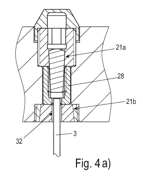
5 Fig. 4 shows in a) the components of the first variant of a hot runner
device accord-
ing to Fig. 3a) in a second operating state without overload and in b) the com-
ponents of a) after the occurrence of another overload case (overload when
moving in the negative X direction) than in Fig. 3;
Fig. 5 shows in a) the components of another - structurally simple ¨
embodiment ac-
cording to the principle of Fig. 2, in b) the components of another
structurally
very simple embodiment according to the principle of Figs. 3 and 4, in which
the head of the needle is formed conically, and in c) the components of a
structurally very simply constructed embodiment according to the principle of
Figs. 3 and 4, wherein the head of the needle is formed cylindrically and a
conical pin forms the abutment of the needle;
Fig. 6 shows in a) a simplified sectional view of a variant of a hot runner
device of the
type of Fig. 1) in the assembled state of self-locking components with force
vectors and angle entries to illustrate the effective mounting forces, and in
b)
the components of a) after the occurrence of a first overload case with the
force vectors and angle entries to illustrate the acting forces;
Fig. 7 shows a diagram of the force ratio between release force/mounting force
of
the self-locking cone connection according to Figs. 2-5 as a function of the
co-
efficient of friction p and with the flank angle a of the cones as parameters,
wherein the constructive embodiment in Fig. 6 is shown in simplified form.
As far as terms such as above and below or right and left are used in the
following,
these relate to the position shown in the respective drawings. The
installation position
may deviate from this, so that the terms are to be understood in a relative
way.
Fig. 1 shows in the interaction of parts a), b) and d) or a), c) and d) a
respective sec-
tional view of a portion of a hot runner device with a needle valve nozzle 1.
This de-
vice is designed for injection-molding plastic components. The plastic
component is
injection-molded in a mold, which is here indicated only by a line S as a mold
plate
CA 03050201 2019-07-15
6
with opening and is otherwise not shown (see, for example, DE 10 2015216 059
Al),
which usually has a mold plate having a gate bore.
Fig. 1 is divided here for the sake of simplicity into four parts which are
arranged from
each other spaced apart, wherein the parts a), b) and d), in an imaginary
juxtaposed
state, represent the hot runner device in a closed position and wherein the
parts a),
c) and d), in an imaginary juxtaposed state, represent the hot runner device
in an
open state.
The outflow end of the needle valve nozzle 1, which is aligned towards the
mold
plate, can be closed in the closed position by a closure end 2 of a shut-off
needle 3,
so that no more plastic can enter from the needle valve nozzle 1 or into the
mold.
In Fig. lb, the shut-off needle 3 has been moved accordingly in the direction
of the
mold (here in the downward direction), so that the needle valve nozzle 1 is
closed. In
contrast, in the open position of Fig. lc, the shut-off needle has been moved
away
from the mold (here in the upward direction), so that the needle valve nozzle
1 is
opened. In this condition, plastic can flow into the mold.
The needle valve nozzle 1 and the shut-off needle 3 have a main extension
direction
X. The shut-off needle 3 is moved in a limited manner when closing and opening
the
needle valve 1 in and against the direction X relative thereto.
The shut-off needle 3 is held for this purpose at its ¨ driven - end facing
away from
the free end 2 (hereinafter also called drive end) 4 in a moving means of a
lifting de-
vice. This moving means may be formed as a lifting plate 5. The moving means
is mov-
able by means of a drive device 6 in the direction X or is itself a part of
the drive de-
vice (e.g. a piston).
The moving means - here the lifting plate 5 - is movable back and forth in a
stroke
volume 33 of a hot runner injection mold with multiple plates 8, 9, 10 in the
X direc-
tion relative to these, wherein in and on these plates a hot runner section 11
with hot
runner flow elements 12, 13, 14, 15 is formed. At the so-called distributor -
flow ele-
ment 15¨ the needle valve nozzle 1 is attached here.
The hot runner flow elements 12 to 15 and the needle valve nozzle 1 each have
a
channel section, wherein these channel sections in their interaction form a
melt guide
channel 16 which opens into an annular space around the shut-off needle 3
between
the closure end 2 of the needle valve 1 and the drive end 4 of the shut-off
needle and
CA 03050201 2019-07-15
7
which extends to the open outlet end of the needle valve nozzle 1, so that by
moving
the shut-off needle 3 the melt flow into the mold plate (at S) can be released
or
closed. A gap is formed between the hot runner elements 12, 13, 14, 15 and the
rest
of the tool 7 to separate the hot or warm area from a region which is
relatively colder
in relation thereto. In order for the plastic melt to remain flowable in the
gate system,
it can be designed in any case to be heatable in sections (see the heater 17).
The movement of the shut-off needle 3 can take place, for example, with the
aid of a
fluid-actuatable drive cylinder 18 as a drive device 6, which has a movable
piston 19
with a piston rod 20 which is directly or indirectly (i.e. via intermediately
connected
means) fastened to the moving means - here the lifting plate 5. The drive
device can
also be realized differently, for example as an electric motor or
electromagnet or as a
hydraulic cylinder. It is also conceivable that the piston 19 itself forms the
moving
means, to which the shut-off needle 3 is releasably attached.
It is readily possible to also attach a plurality of the shut-off needles 3 to
the lifting
plate 5 and still move the lifting plate 5 with only one drive device.
The shut-off needle 3 shown here is detachably fastened with its drive end 4
via an
overload protection device, which is designed here as a (first) frictional
connection or
as a frictional connection 21 (see also Fig. 2), in or on the moving means,
here the
lifting plate 5. It is provided in particular that the overload protection
device is realized
as follows: the shut-off needle 3 is connected in at least one first direction
of move-
ment directly or indirectly to the moving means, in particular a lifting
means, via at
least one frictional connection 21 which is releasable when exceeding a limit
force. In
this case, the frictional connection 21 is formed here according to an
advantageous
variant as a self-locking connection.
For this purpose, the at least one frictional connection 21 is designed such
that the
shut-off needle is held securely and firmly in the moving means in normal
operation
during the reciprocation of the moving means for opening and closing the
needle
valve nozzle 1. Only in an overload case at an excess of a limit force, the
frictional
force of the frictional connection 21 is overcome, so that the shut-off needle
3 and its
end of movement 4 is released from its tight fit (e.g. formed by a pin 23,
sleeve 24
and second sleeve 28) in the moving means, here the lifting plate 5, so that
the mov-
ing means can move relative to the shut-off needle 3 in the X direction. Thus,
the
overload protection function/device is implemented with simple design means.
CA 03050201 2019-07-15
8
Hereinafter, various advantageous embodiments of the invention are considered
in
more detail, to which the invention is not limited.
In a first preferred variant, the moving means, in this case the lifting plate
5, are pen-
etrated by a stepped bore 22, which may partially have a thread (Figs. 1 to
5). The
drive end 4 of the shut-off needle 3 engages in this bore 22. In this case, a
pin 23 is
attached to the drive end 4 of the shut-off needle 3 in the axial extension of
the same.
This pin 23 may alternatively - see Figs. 5a and 5b, for example - also be
integrally
formed on the drive end 4 of the shut-off needle 3.
The pin 23 has a conical outer shape and is directly releasably held and fixed
with
frictional engagement in the conical bore 22'. For this purpose, the pin 23 is
pressed
during its assembly with a predetermined force into the bore 22'. The
frictional con-
nection 21 is thus formed here by the pin 23 with the outer cone A and the
bore 22'
with the at least partially provided inner cone I and the friction between pin
23 and
bore 22' (see Figs. 5 and 6).
Preferably, the bore 22' is formed at least in sections in an inner conically
corre-
sponding manner to the conical shape of the pin 23 (see Figs. 5 and 6). Here
the pin
narrows from top to bottom, i.e. in the direction X, in which the shut-off
needle 3 is
moved in a closure movement into the position of Fig. 1c).
Alternatively, the pin 23 can also be inserted directly into a bore 22 of the
moving
means, in particular the lifting plate 5 (similar to Fig. 5a, not shown here
in the draw-
ing), or into a component inserted into the moving means, in particular the
lifting plate
5 (Figs. 2 to 4).
Preferably, this component may be a sleeve 24/31 .The sleeve 24 is configured
in a
further preferred embodiment as a screw with an external thread, which is
inserted
into an internally threaded portion of the bore 22 and itself has an inner
bore 22'
which is concentric to the bore 22. The term "bore" is to be understood here
and
throughout this application in the sense of an opening, in particular a
through-hole,
which need not necessarily be made by drilling.
The moving means 5 presses in this case via the pin 23 during the closing
movement
on the needle valve head 27 and the free end 4 of the shut-off needle 3 to
move the
shut-off needle 3 in an axially linear manner in the X direction.
CA 03050201 2019-07-15
9
Both the pin 23 and either the bore 22 in the moving means or the bore 22',
which is
preferably concentric thereto, in the component, in particular the sleeve 24,
respec-
tively comprise a corresponding outer cone A and an inner cone I over their
entire
length in the X direction or at least in sections.
The pin 23 is or was pressed with a defined force during its assembly into the
moving
means 5 or, in this case, into the sleeve 24 via its outer cone A into the
inner cone I
of the surrounding body - the sleeve 24 or directly the moving means.
According to a variant it can be provided that the shut-off needle 3 has an
outer cone
A instead of a separate pin 23 directly at its one end and is thus directly
frictionally
connected to the moving means 5 (or its sleeve 24). The shut-off needle 3 then
has
no separate pin, but forms this pin with its end itself. This variant is shown
in Fig. 5.
Fig. 5 shows in a) the components of an embodiment according to the principle
of
Fig. 2, in which the bore 22 in the lifting plate 5 is formed in a directly
conical manner
and in which the drive end 4 of the shut-off needle 3 is formed in a
corresponding
manner conically as a pin.
Overall, the pin 23 is connected in a frictionally engaged and self-locking
manner to
the surrounding body - preferably the sleeve 24 or the mold plate 5 - so that
a trans-
latory movement of the moving means 5 moves the pin and thus the shut-off
needle
3 in the direction X or in the opposite direction -X. In this way, the
connecting needle
3 can be moved back and forth between the closed position (see, for example,
Fig. 1
b) and the open position (see, for example, Fig. 1 c).
During the closing movement, in which the moving means - here the lifting
plate 5 - is
moved in the direction -X, the closing needle 3 exerts an axial force on the
pin 23 or
on the frictional engagement region between the inner cone I and the outer
cone A. If
this axial force exceeds the static friction of the frictional connection, the
pin 23 is re-
leased from the surrounding body - preferably the sleeve 24 or the lifting
plate 5 - and
the shut-off needle 3 is no longer moved by the body or the drive device in
the clos-
ing direction -X.
In other words, this means that the pin 23 triggers and no longer serves as an
abut-
ment for the shut-off needle 3. This can be seen, for example, in Fig. 2b.
Here, the
frictional connection 21 has released after moving the moving means (this
movement
is not visible here) and the shut-off needle 3 was therefore able to move
relative to
CA 03050201 2019-07-15
the moving means. Damage to the shut-off needle 3 can or could be avoided in
this
way.
As a result of a suitable adjustment of the mounting force, the limit force or
critical
force at which the pin 23 is to trigger can also be adjusted. In this way, the
shut-off
5 needle 3 is easily preserved from damage due to overload.
The moving means can be configured differently. It can, for example, also
directly be
a piston or, for example, the previously described lifting plate 5. A lifting
plate 5 is
preferably - but not only - then chosen if one or more of the shut-off needles
are to be
installed in it.
10 Optionally, a cover cap 26 may be placed on the sleeve 24 at its end
facing away
from the shut-off needle 3 (Fig. 2a), which advantageously covers the bore 22
and
prevents the released pin 23 from falling out into the stroke volume of the
lifting plate.
It is further advantageous if the shut-off needle 3, according to one variant,
has a
head 27 at its end 4 with a diameter which is widened in relation to the other
diame-
.. ter of the shut-off needle 3, with which it rests axially on the pin 23
and/or is fixed
thereto, so that good power transmission between the pin 23 and the shut-off
needle
3 is ensured, in particular if they are not formed integrally.
According to a further optional further development, it is also advantageously
provid-
ed that below the sleeve 24, a second sleeve 28 is inserted into the bore 22.
This
further sleeve 28 may be fixed between a shoulder of the stepped bore 22 of
the
moving means and the first sleeve 24 - in particular as this sleeve 24 is
formed as a
screw. The second sleeve 28 preferably itself has a stepped inner bore 29. In
this
case, the head of the needle 27 is movably guided in the inner bore 29. In
this case it
strikes down against a collar of inner bore 29 so that it cannot escape from
the inner
bore 29. Usually, the dimensional adjustment is chosen so that the head of the
nee-
dle 27 between the pin 23 and the collar of the stepped bore 29 has a slight
play, so
that the needle 3 can move transversely to the main movement direction X in
order to
avoid thermal stresses.
It is clearly shown in Fig. 2a that the pin 23 is pressed with its outer cone
A into the
inner cone of the sleeve 24. The shut-off needle 3 is moved upward (see also
Fig.
1c), which here corresponds to an open position on the needle valve nozzle 1.
In Fig.
2b it can be seen that the shut-off needle 3 and the pin 23 have moved
relative to the
CA 03050201 2019-07-15
11
lifting plate 5 (lifting movement, it can be seen in each case from the offset
of the lift-
ing plate 5 between the Figs. 2a and 2b of the respective stroke). The lifting
plate 5
was moved in the downward direction. The shut-off needle 3 has not followed
this
movement because a disturbing force acts on it in an unrecognizable manner
here,
which is greater than the press-in force for mounting the pin 3 in the moving
means,
in particular in the first sleeve 24. The pin 23 has been released from its
press
fit/friction fit and has not followed the movement of the moving means.
The variant of Figs. 3 and 4 differs from the variant of Fig. 2 in that the
overload pro-
tection device is designed such that it can trigger in two directions +X and -
X.
For this purpose, the overload protection device advantageously has two (here
local-
ly separate) frictional engagement connections 21a and 21b.
Constructively, this can be achieved in various ways. According to the variant
shown
in Figs. 3 and 4, a (here second) screw sleeve 30 is inserted into a lower
portion of
the bore 22, which is stepped in this case, in addition to the frictional
connection 21a.
.. This screw sleeve 30 is mounted on the side of the lifting plate 5 which is
opposite
the first sleeve 24. The screw sleeve 30 has an inner cone I. An inner sleeve
31 is
pressed into said core, which sleeve has an outer cone A. At the same time,
this
cone press-fit connection 21b tapers in the opposite direction (here in the
direction -
x) like the first cone press-fit connection 21a.
The shut-off needle 3 passes through the inner sleeve 31. This is in turn is
designed
here such that the second sleeve 28 rests upwardly on it. The pin 23 and/or
the head
27 cannot fall out of the lower sleeve 28 downwardly or exit therefrom, since
the di-
ameter of at least one or both of these elements is greater than the inner
diameter of
the bore 32 of the inner sleeve 31.
The function of the second frictional connection 21b as part of the overload
protection
device is as follows:
The shut-off needle 3 has been moved in Fig. 4a with the moving means in the
downward direction, which here corresponds to a closed position on the needle
valve
nozzle 1. If the shut-off needle 3 is now to be moved from the closed position
to an
open position, the head 27 bears against the lower annular collar of the
second
sleeve 28, so that the shut-off needle 3 is co-lifted by the movement of the
moving
CA 03050201 2019-07-15
12
means together with the sleeves and pins 23, 24, 28, 30, 31, which are screwed
and
inserted therein.
In Fig. 4b it can be seen that the shut-off needle 3 or the head 27, the
second sleeve
28 and the inner sleeve 31 have moved relative to the lifting plate 5. The
lifting plate
5 has been moved upwards. The shut-off needle 3 has not followed this movement
since a disturbing force acts on it in a manner not recognizable here, which
is greater
than the pressing force for mounting the outer conical sleeve 31 in the moving
means, in particular in the screw sleeve 30. The inner sleeve 31, which is
conical on
the outside, has been released from its press fit/friction fit in the mounting
means,
1.0 particularly in the internally conical screw sleeve 30, and has not
followed the move-
ment of the moving means.
According to Figs. 5b and Sc, two overload protection devices are also
respectively
realized as overload safeguards both during lifting and when lowering the shut-
off
needle 3 with two cone press-fit connections 21a, 21b, which act in different
direc-
tions. However, the structural design is particularly simple, which is
advantageous
but not mandatory for the function of the invention.
Also according to Figs. 5b and Sc, either the conical drive end 4 or a conical
pin 23 is
inserted into a sleeve 31 having a bore 22', which is formed correspondingly
conical
to the pin 23. In this way, in turn, a cone press-fit connection 21a is
realized. The in-
ner cone and the outer cone expand in a first direction "upwards" (direction -
X). This
corresponds to the first overload protection device according to Fig. 5a. The
sleeve
31 thus corresponds here in each case also to the sleeve 24 of Figs. 2 to 4.
In addition, however, the outer contour of the sleeve 31 and the inner contour
of the
bore 22 in the lifting plate 5 are designed correspondingly conical. The inner
cone
and outer cone expand in a second direction "down" (direction X). According to
Figs.
5b and c, the bore 22 thus conically widens in the lifting plate downwards in
the direc-
tion X, so that the sleeve 31 can be released under overload from its friction
fit in Fig.
5b in the downward direction. This is the respective second overload
protection de-
vice.
According to Fig. 5b, the drive end 4 of the shut-off needle 3 is integrally
formed in a
conical manner and thus forms the pin 23 per se. According to Fig. Sc,
however, a
CA 03050201 2019-07-15
13
pin 23 is placed on the drive end 4 (which in turn is formed here as a
cylindrical head
27).
These variants are structurally simple and still well functional.
As a result of the two friction connections according to Figs. 3 to 5, the
overload pro-
tection device can be reliably triggered in each case in both possible
directions of
movement of the needle valve nozzle.
In the following, the mode of operation of an overload protection device will
be de-
scribed in more detail again with reference to Figs. 6 and 7, which shows a
construc-
tively simplified but nevertheless theoretically functional design.
1.0 During its initial mounting, the conical pin 23 is pressed by means of
a suitable de-
vice (not visible here) with a force Fm - see Fig. 6a - into the conical bore
22' of the
sleeve 24. Consequently, a normal force FN is built up via the flanks (flank
angle a) of
the cone of the conical frictional connection. The friction (coefficient of
friction p =
tanp) acts against the mounting force Fm and generates the frictional force
FR. Thus,
the theoretically achievable normal force FN(th) is reduced and the x-
component of the
resultant force FE is reduced to the remaining spreading force Fs. As long as
the y
component FN (y) of the normal force FN is smaller than the y-component FR (y)
of the
frictional force FR, there is self-locking and the conical pin can be pushed
out again
only with a release force FL (see Fig. 6b).
The force diagram of Fig. 7 shows that self-locking is present for:
P
The force relationships during a disassembly process are illustrated in Fig.
6b .The
exact release force FL can be seen in Fig. 7. For this, it must be noted that
when the
mounting force Fm is removed, the direction of the frictional force FR is
reversed and
thus the normal force FN, with the same spreading force Fs, becomes smaller be-
cause the x-component of the frictional force FR(x) now counteracts the
spreading
force F. The necessary release force FL is mainly determined by the mounting
force
Fm and, as the force diagrams show, depends on both the flank angle a and the
coef-
ficient of friction p = tan p.
.. How the factors affect the release force (qualitatively) is shown in Fig.
7. The follow-
ing applies:
CA 03050201 2019-07-15
14
FL tan( p ¨
F24 tan(p __ , p = arctan(p)
CA 03050201 2019-07-15
List of reference numerals
Needle valve nozzle 1
5 Closure end 2
Shut-off needle 3
Drive end 4
Lifting plate 5
Drive device 6
10 Tool 7
Plates 8,9, 10
Hot runner section 11
Hot runner flow elements 12, 13, 14, 15
Melt guide channel 16
15 Heating 17
Drive cylinder 18
Piston 19
Piston rod 20
Frictional connection 21, 21a, 21b
Bore 22
Bore 22'
Pin 23
Sleeve 24
Cover cap 26
Head 27
Second sleeve 28
Inner bore 29
Screw sleeve 30
Inner sleeve 31
Bore 32
Stroke volume 33
Outer cone A
Inner cone I
CA 03050201 2019-07-15
16
Direction X
Mold plate S
Angle a
Friction angle p
Mounting force Fm
Normal force FN
Frictional force FR
Resultant force FE
Spreading force Fs
Release force FL
Coefficient of friction 1-1,